EP0792694A2 - Procédé et dispositif pour commander l'alimentation d'une poudre fluidisée à partir d'un réservoir - Google Patents
Procédé et dispositif pour commander l'alimentation d'une poudre fluidisée à partir d'un réservoir Download PDFInfo
- Publication number
- EP0792694A2 EP0792694A2 EP97102463A EP97102463A EP0792694A2 EP 0792694 A2 EP0792694 A2 EP 0792694A2 EP 97102463 A EP97102463 A EP 97102463A EP 97102463 A EP97102463 A EP 97102463A EP 0792694 A2 EP0792694 A2 EP 0792694A2
- Authority
- EP
- European Patent Office
- Prior art keywords
- powder
- container
- tube
- air
- fluidized
- Prior art date
- Legal status (The legal status is an assumption and is not a legal conclusion. Google has not performed a legal analysis and makes no representation as to the accuracy of the status listed.)
- Granted
Links
Images

Classifications
-
- B—PERFORMING OPERATIONS; TRANSPORTING
- B05—SPRAYING OR ATOMISING IN GENERAL; APPLYING FLUENT MATERIALS TO SURFACES, IN GENERAL
- B05B—SPRAYING APPARATUS; ATOMISING APPARATUS; NOZZLES
- B05B5/00—Electrostatic spraying apparatus; Spraying apparatus with means for charging the spray electrically; Apparatus for spraying liquids or other fluent materials by other electric means
- B05B5/16—Arrangements for supplying liquids or other fluent material
- B05B5/1691—Apparatus to be carried on or by a person or with a container fixed to the discharge device
-
- B—PERFORMING OPERATIONS; TRANSPORTING
- B05—SPRAYING OR ATOMISING IN GENERAL; APPLYING FLUENT MATERIALS TO SURFACES, IN GENERAL
- B05B—SPRAYING APPARATUS; ATOMISING APPARATUS; NOZZLES
- B05B5/00—Electrostatic spraying apparatus; Spraying apparatus with means for charging the spray electrically; Apparatus for spraying liquids or other fluent materials by other electric means
- B05B5/025—Discharge apparatus, e.g. electrostatic spray guns
- B05B5/03—Discharge apparatus, e.g. electrostatic spray guns characterised by the use of gas, e.g. electrostatically assisted pneumatic spraying
- B05B5/032—Discharge apparatus, e.g. electrostatic spray guns characterised by the use of gas, e.g. electrostatically assisted pneumatic spraying for spraying particulate materials
-
- B—PERFORMING OPERATIONS; TRANSPORTING
- B05—SPRAYING OR ATOMISING IN GENERAL; APPLYING FLUENT MATERIALS TO SURFACES, IN GENERAL
- B05B—SPRAYING APPARATUS; ATOMISING APPARATUS; NOZZLES
- B05B5/00—Electrostatic spraying apparatus; Spraying apparatus with means for charging the spray electrically; Apparatus for spraying liquids or other fluent materials by other electric means
- B05B5/16—Arrangements for supplying liquids or other fluent material
- B05B5/1683—Arrangements for supplying liquids or other fluent material specially adapted for particulate materials
-
- B—PERFORMING OPERATIONS; TRANSPORTING
- B05—SPRAYING OR ATOMISING IN GENERAL; APPLYING FLUENT MATERIALS TO SURFACES, IN GENERAL
- B05B—SPRAYING APPARATUS; ATOMISING APPARATUS; NOZZLES
- B05B7/00—Spraying apparatus for discharge of liquids or other fluent materials from two or more sources, e.g. of liquid and air, of powder and gas
- B05B7/14—Spraying apparatus for discharge of liquids or other fluent materials from two or more sources, e.g. of liquid and air, of powder and gas designed for spraying particulate materials
- B05B7/1404—Arrangements for supplying particulate material
- B05B7/1413—Apparatus to be carried on or by a person, e.g. by hand; Apparatus comprising a container fixed to the discharge device
-
- Y—GENERAL TAGGING OF NEW TECHNOLOGICAL DEVELOPMENTS; GENERAL TAGGING OF CROSS-SECTIONAL TECHNOLOGIES SPANNING OVER SEVERAL SECTIONS OF THE IPC; TECHNICAL SUBJECTS COVERED BY FORMER USPC CROSS-REFERENCE ART COLLECTIONS [XRACs] AND DIGESTS
- Y10—TECHNICAL SUBJECTS COVERED BY FORMER USPC
- Y10S—TECHNICAL SUBJECTS COVERED BY FORMER USPC CROSS-REFERENCE ART COLLECTIONS [XRACs] AND DIGESTS
- Y10S118/00—Coating apparatus
- Y10S118/05—Fluidized bed
Definitions
- the invention relates to a method according to the preamble of claim 1 and a device according to the preamble of claim 2 for controlling the exit of a fluidized solid from a container.
- the method and the device can generally be used for closing or partially or completely opening an outlet opening on a container for fluidized solid, wherein an increased pressure or ambient air pressure can prevail in the container.
- the method and the device are particularly suitable for use in powder spraying devices for electrostatic painting.
- a powder spraying device is described, for example, in the unpublished German patent application P 195 370 89.
- the structure of this powder spraying device is explained in more detail below with reference to FIG. 1.
- the powder spraying device has a mechanical locking system for the powder outlet.
- the invention is therefore based on the object of specifying a method and a device for controlling the outlet of a fluidized solid, the aforementioned disadvantages being to be avoided.
- the method and the device have the effect that, by introducing closing air into the sampling tube, the powder is pushed back out of the tube into the container and the powder discharge is thereby stopped.
- a nozzle usually arranged at the outlet is cleaned with the help of the closing air at each spray stop.
- the mass flow of the fluidized solid is easy to change of the closing air flow controllable.
- the solids output can also be set to intermediate values between zero and a maximum value by setting appropriate pressure ratios.
- FIG. 1 shows a powder spraying device 1 already described in application P 195 370 89, which essentially consists of a closed container 2 with a first chamber 3 and a second chamber 4.
- a compressed air supply line 5 opens into the first chamber 3.
- Compressed air 7 enters the second chamber 4 through a frit 6.
- Powder 8 is located in the second chamber 4 and can be filled through a powder supply opening 9.
- the fluidized powder 8 is removed from the area of the fluid bed through a pipe 25 and is led out through a nozzle 11 arranged on the side of the container 2 and closable with a mechanical closing device 13.
- needles are arranged as corona electrodes 14, which are connected to a high-voltage source (not shown) and which charge the emerging powder particles.
- the shape of the emerging powder cloud 15 can be determined by the nozzle 11 and an additional impact body 16.
- the shape and arrangement of the electrodes 14 can be adapted to this.
- the air supply can be influenced with the aid of a controllable air inlet valve 17 and the air supply rate can be measured with the aid of a flow meter 18.
- the outlet opening 10 for fluidizing air is closed off by a controllable outlet valve 19, with which a defined flow resistance can be set.
- the air pressure p 1 in the first chamber 3 and the air pressure p 4 above the powder bed 8 can be regulated via the valves 17 and 19 with the aid of a control and regulating device, not shown.
- the pressures p 1 and p 4 are measured using suitable pressure sensors.
- the ambient air pressure is denoted by p 0 .
- p 2 With p 2 the air pressure above the frit 6 and thus immediately below the fluidized powder bed is designated.
- the pressure drop p 1 -p 2 depends on the selected frit 6 and must be taken into account when dimensioning.
- the powder is tapped from the interior of the chamber 4 through a pipe 25 attached to the nozzle 11. This ensures a high level of uniformity of the powder output.
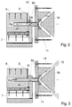
- FIG. 2 and 3 each show in a schematic diagram the embodiment of a locking system according to the invention for the exit of fluidized powder, which takes the place of the mechanical locking system shown in FIG. 1, FIG. 2 showing a closed state and FIG. 3 the opened state. 1 correspond to the same components.
- FIG. 2 shows a section of the container 2 with the extraction tube 25 for fluidized powder 8.
- the jacket of the extraction tube 25 has an opening 50 into which an air tube 51 opens. Closing air L S can be introduced into the air tube 51. The method for controlling the fluid powder outlet and thus the operation of the device shown in FIGS. 2 and 3 is explained below.
- a closing air pressure p R is established in the air pipe 51.
- the closing air pressure p R in the extraction tube 25 is greater than the pressure p 3 in the container 2, powder leakage is prevented; ie at a pressure ratio p R / p 3 > 1, the fluid powder 8 is pushed back into the container 2. If the closing air pressure p R in the extraction tube 25 is less than the pressure p 3 in the container 2, that is to say the ratio p R / p 3 ⁇ 1, fluidized powder emerges.
- a numerical example can further clarify which air pressures are required for closing.
- a closing air pressure p R of at least 2.1 bar is required in the case of a container pressure p 3 of 2 bar (corresponds to 1 bar overpressure) in order to discharge the powder stop completely.
- a closing air pressure p R of at least 2.4 bar is required under otherwise identical conditions as mentioned before in order to completely stop the powder output.
- FIG. 2 shows a state in which a closing air pressure p R that is greater than the fluid bed pressure p 3 is set by appropriately introducing closing air L S into the extraction tube 25. There is no powder leakage.
- the closing air L S flows partly into the container 2 and partly through the nozzle 11.
- Fig. 3 shows a state in which the supply of closing air L S is completely shut off and powder can thereby be ejected.
Landscapes
- Electrostatic Spraying Apparatus (AREA)
- Application Of Or Painting With Fluid Materials (AREA)
- Glanulating (AREA)
- Devices And Processes Conducted In The Presence Of Fluids And Solid Particles (AREA)
- Air Transport Of Granular Materials (AREA)
- Crucibles And Fluidized-Bed Furnaces (AREA)
Applications Claiming Priority (2)
| Application Number | Priority Date | Filing Date | Title |
|---|---|---|---|
| DE19606214A DE19606214B4 (de) | 1996-02-20 | 1996-02-20 | Verfahren und Einrichtung zur Steuerung des Austritts eines fluidisierten Feststoffs aus einem Behälter |
| DE19606214 | 1996-02-20 |
Publications (3)
| Publication Number | Publication Date |
|---|---|
| EP0792694A2 true EP0792694A2 (fr) | 1997-09-03 |
| EP0792694A3 EP0792694A3 (fr) | 1998-05-27 |
| EP0792694B1 EP0792694B1 (fr) | 2003-03-12 |
Family
ID=7785865
Family Applications (1)
| Application Number | Title | Priority Date | Filing Date |
|---|---|---|---|
| EP97102463A Expired - Lifetime EP0792694B1 (fr) | 1996-02-20 | 1997-02-15 | Procédé et dispositif pour commander l'alimentation d'une poudre fluidisée à partir d'un réservoir |
Country Status (6)
| Country | Link |
|---|---|
| US (1) | US5800876A (fr) |
| EP (1) | EP0792694B1 (fr) |
| JP (1) | JP3987152B2 (fr) |
| KR (1) | KR970061773A (fr) |
| AT (1) | ATE234159T1 (fr) |
| DE (2) | DE19606214B4 (fr) |
Cited By (1)
| Publication number | Priority date | Publication date | Assignee | Title |
|---|---|---|---|---|
| DE102004013153A1 (de) * | 2004-03-17 | 2005-10-06 | Itw Gema Ag | Verfahren und Vorrichtung zum Fördern von Pulver, insbesondere Pulver zum Sprühbeschichten von Gegenständen |
Families Citing this family (8)
| Publication number | Priority date | Publication date | Assignee | Title |
|---|---|---|---|---|
| ITMI20010654A1 (it) * | 2001-03-28 | 2002-09-28 | Ines Urbani | Dispositivo per verniciatura elettrostatica ad emissione lineare di polvere attraverso una doppia fenditura di qualsivoglia lunghezza per us |
| DE10138917A1 (de) | 2001-08-08 | 2003-03-06 | Itw Gema Ag | Pulversprühbeschichtungsvorrichtung |
| US7273339B2 (en) * | 2003-03-07 | 2007-09-25 | Haden Schweitzer Corporation | Powder transport method and apparatus |
| US6988698B2 (en) * | 2004-04-22 | 2006-01-24 | Lucasay Manufacturing Co. | Appliance mounting apparatus |
| BE1015883A3 (fr) * | 2004-06-08 | 2005-10-04 | Occhio | Procede et dispositif de dispersion de poudres seches. |
| US20080152437A1 (en) * | 2006-12-26 | 2008-06-26 | Illinois Tool Works Inc. | Pulverulent material transport |
| US20080205189A1 (en) * | 2007-02-27 | 2008-08-28 | Illinois Tool Works Inc. | Dense phase pump for pulverulent material |
| KR101329032B1 (ko) * | 2011-04-20 | 2013-11-14 | 주식회사 실리콘밸류 | 다결정 실리콘 제조장치 및 이를 이용한 다결정 실리콘의 제조방법 |
Family Cites Families (14)
| Publication number | Priority date | Publication date | Assignee | Title |
|---|---|---|---|---|
| FR2314775A1 (fr) * | 1975-06-18 | 1977-01-14 | Inst Francais Du Petrole | Appareillage pour former une couche d'un produit pulverulent sur la surface d'un objet |
| US4165134A (en) * | 1977-08-16 | 1979-08-21 | The Continental Group, Inc. | Pneumatic powder flow diverting device |
| FR2521170B1 (fr) * | 1982-02-09 | 1986-11-21 | Dietrich & Cie De | Procede pour l'emaillage d'objets par pistolage electrostatique |
| DE3244742C2 (de) * | 1982-12-03 | 1986-07-03 | Bergwerksverband Gmbh, 4300 Essen | Vorrichtung zum Austragen von Feststoffpartikeln aus einem Behälter, insbesondere einem Wirbelschichtreaktor sowie Verfahren zum Betreiben einer solchen Vorrichtung |
| HU188492B (en) * | 1983-09-28 | 1986-04-28 | Eroemue- Eshalozattervezoe Vallalat,Hu | Device for measuring and controlling volume flow of fluidizable powdery or granulat materials |
| DE3544915A1 (de) * | 1985-12-19 | 1987-06-25 | Basf Ag | Dosiervorrichtung zum regelbaren einbringen von rieselfaehigen, pulverfoermigen stoffen in unter druck stehende raeume |
| JPH0615050B2 (ja) * | 1986-02-05 | 1994-03-02 | ノードソン株式会社 | 粉粒体の断続スプレイ塗布方法とそのガン |
| DE4010914C1 (en) * | 1990-04-04 | 1991-07-11 | Wagner International Ag, Altstaetten, Ch | Fluidising and convey set=up for electrostatic powder coating appts. - has container pivotable about 180 deg. on frame and with fluidising plate on lid |
| AU6227094A (en) * | 1992-12-17 | 1994-07-04 | Nordson Corporation | Improved powder coating system for difficult to handle powders |
| GB2277469B (en) * | 1993-04-27 | 1996-07-24 | Itw Ltd | An electrostatic system |
| DE4325044C2 (de) * | 1993-07-26 | 2002-07-18 | Itw Gema Ag | Pulverfördervorrichtung, insbesondere für Beschichtungspulver |
| DE4436919C2 (de) * | 1994-10-15 | 1997-06-05 | Boris Petrovic Dr Ing Leonov | Einrichtung zur tribostatischen Pulverlackbeschichtung |
| US5558713A (en) * | 1994-10-31 | 1996-09-24 | The Procter & Gamble Company | Method and apparatus for forming a pulsed stream of particles for application to a fibrous web |
| DE19537089A1 (de) * | 1995-10-05 | 1997-04-10 | Abb Research Ltd | Verfahren und Einrichtung zum Pulversprühen |
-
1996
- 1996-02-20 DE DE19606214A patent/DE19606214B4/de not_active Expired - Fee Related
-
1997
- 1997-02-15 DE DE59709463T patent/DE59709463D1/de not_active Expired - Lifetime
- 1997-02-15 AT AT97102463T patent/ATE234159T1/de not_active IP Right Cessation
- 1997-02-15 EP EP97102463A patent/EP0792694B1/fr not_active Expired - Lifetime
- 1997-02-19 JP JP03513797A patent/JP3987152B2/ja not_active Expired - Fee Related
- 1997-02-19 KR KR1019970004979A patent/KR970061773A/ko not_active Withdrawn
- 1997-02-20 US US08/804,129 patent/US5800876A/en not_active Expired - Lifetime
Cited By (1)
| Publication number | Priority date | Publication date | Assignee | Title |
|---|---|---|---|---|
| DE102004013153A1 (de) * | 2004-03-17 | 2005-10-06 | Itw Gema Ag | Verfahren und Vorrichtung zum Fördern von Pulver, insbesondere Pulver zum Sprühbeschichten von Gegenständen |
Also Published As
| Publication number | Publication date |
|---|---|
| JP3987152B2 (ja) | 2007-10-03 |
| JPH09313992A (ja) | 1997-12-09 |
| ATE234159T1 (de) | 2003-03-15 |
| US5800876A (en) | 1998-09-01 |
| DE59709463D1 (de) | 2003-04-17 |
| DE19606214B4 (de) | 2006-06-01 |
| EP0792694B1 (fr) | 2003-03-12 |
| EP0792694A3 (fr) | 1998-05-27 |
| KR970061773A (ko) | 1997-09-12 |
| DE19606214A1 (de) | 1997-08-21 |
Similar Documents
| Publication | Publication Date | Title |
|---|---|---|
| EP0021182B2 (fr) | Procédé et dispositif pour l'alimentation en peinture des installations de peinture | |
| EP0347607B1 (fr) | Procédé et dispositif pour amener un produit à pulvériser à une pluralité de postes de pulvérisation | |
| DE20118531U1 (de) | Vorrichtung an einer Lackiereinrichtung zum Reinigen einer Lackleitung | |
| CH620600A5 (fr) | ||
| EP0282049A2 (fr) | Système encreur pour une imprimante matricielle à jet d'encre | |
| EP3957404A1 (fr) | Système d'application permettant de revêtir des composants et dispositif de revêtement | |
| DE19606214B4 (de) | Verfahren und Einrichtung zur Steuerung des Austritts eines fluidisierten Feststoffs aus einem Behälter | |
| EP0767006A1 (fr) | Méthode et dispositif d'alimentation en poudre d'un appareil de revêtement à poudre | |
| WO2000058019A1 (fr) | Procede et dispositif de remplissage d'un reservoir pressurise avec un fluide | |
| EP3515354A1 (fr) | Système de nettoyage dentaire, récipient de poudre ainsi qu'insert pour récipient de poudre | |
| DE4005607C1 (fr) | ||
| DE2424009A1 (de) | Foerdervorrichtung fuer fluidfoermiges pulver | |
| EP1073531A1 (fr) | Dispositif et procede de lavage alterne sous pression | |
| EP0796645A1 (fr) | Procédé pour commander le nettoyage de filtres lors de la séparation de particules ainsi que dispositif pour la réalisation du procédé | |
| DE1550462A1 (de) | Stroemungsmittel-Steuerventil | |
| DE9106610U1 (de) | Sprühbeschichtungsvorrichtung | |
| EP0263249B1 (fr) | Dispositif de dosage | |
| EP0720871B1 (fr) | Dispositif pour l'application de produits visqueux sous forme de bandes | |
| AT402799B (de) | Verfahren zur steuerung der abreinigung von filtern sowie einrichtung zur ausführung dieses verfahrens | |
| EP0335076B1 (fr) | Frein pneumatique à action directe pour véhicules ferroviaires | |
| EP1477231A2 (fr) | Dispositif pour la préservation des espaces creux | |
| DE1652298C3 (de) | Vorrichtung zur Abgabe von Klebstoff | |
| DE3530119A1 (de) | Vorrichtung fuer webmaschinen und verfahren zu deren betrieb | |
| EP1556647A1 (fr) | Procede et dispositif de prelevement d'echantillons liquides contenus dans des recipients sous pression | |
| AT233473B (de) | Verfahren zur Regelung der von einer Verteilervorrichtung für einen pulverförmigen Feststoff abgegebenen Pulvermenge |
Legal Events
| Date | Code | Title | Description |
|---|---|---|---|
| PUAI | Public reference made under article 153(3) epc to a published international application that has entered the european phase |
Free format text: ORIGINAL CODE: 0009012 |
|
| AK | Designated contracting states |
Kind code of ref document: A2 Designated state(s): AT BE CH DE DK ES FI FR GB IT LI NL SE |
|
| PUAL | Search report despatched |
Free format text: ORIGINAL CODE: 0009013 |
|
| AK | Designated contracting states |
Kind code of ref document: A3 Designated state(s): AT BE CH DE DK ES FI FR GB IT LI NL SE |
|
| 17P | Request for examination filed |
Effective date: 19980723 |
|
| 17Q | First examination report despatched |
Effective date: 19990108 |
|
| GRAG | Despatch of communication of intention to grant |
Free format text: ORIGINAL CODE: EPIDOS AGRA |
|
| GRAG | Despatch of communication of intention to grant |
Free format text: ORIGINAL CODE: EPIDOS AGRA |
|
| GRAH | Despatch of communication of intention to grant a patent |
Free format text: ORIGINAL CODE: EPIDOS IGRA |
|
| GRAH | Despatch of communication of intention to grant a patent |
Free format text: ORIGINAL CODE: EPIDOS IGRA |
|
| GRAA | (expected) grant |
Free format text: ORIGINAL CODE: 0009210 |
|
| AK | Designated contracting states |
Designated state(s): AT BE CH DE DK ES FI FR GB IT LI NL SE |
|
| PG25 | Lapsed in a contracting state [announced via postgrant information from national office to epo] |
Ref country code: NL Free format text: LAPSE BECAUSE OF FAILURE TO SUBMIT A TRANSLATION OF THE DESCRIPTION OR TO PAY THE FEE WITHIN THE PRESCRIBED TIME-LIMIT Effective date: 20030312 Ref country code: FI Free format text: LAPSE BECAUSE OF FAILURE TO SUBMIT A TRANSLATION OF THE DESCRIPTION OR TO PAY THE FEE WITHIN THE PRESCRIBED TIME-LIMIT Effective date: 20030312 |
|
| REG | Reference to a national code |
Ref country code: GB Ref legal event code: FG4D Free format text: NOT ENGLISH |
|
| REG | Reference to a national code |
Ref country code: CH Ref legal event code: EP |
|
| GBT | Gb: translation of ep patent filed (gb section 77(6)(a)/1977) |
Effective date: 20030312 |
|
| REF | Corresponds to: |
Ref document number: 59709463 Country of ref document: DE Date of ref document: 20030417 Kind code of ref document: P |
|
| PG25 | Lapsed in a contracting state [announced via postgrant information from national office to epo] |
Ref country code: SE Free format text: LAPSE BECAUSE OF FAILURE TO SUBMIT A TRANSLATION OF THE DESCRIPTION OR TO PAY THE FEE WITHIN THE PRESCRIBED TIME-LIMIT Effective date: 20030612 Ref country code: DK Free format text: LAPSE BECAUSE OF FAILURE TO SUBMIT A TRANSLATION OF THE DESCRIPTION OR TO PAY THE FEE WITHIN THE PRESCRIBED TIME-LIMIT Effective date: 20030612 |
|
| NLV1 | Nl: lapsed or annulled due to failure to fulfill the requirements of art. 29p and 29m of the patents act | ||
| PG25 | Lapsed in a contracting state [announced via postgrant information from national office to epo] |
Ref country code: ES Free format text: LAPSE BECAUSE OF FAILURE TO SUBMIT A TRANSLATION OF THE DESCRIPTION OR TO PAY THE FEE WITHIN THE PRESCRIBED TIME-LIMIT Effective date: 20030930 |
|
| ET | Fr: translation filed | ||
| PLBE | No opposition filed within time limit |
Free format text: ORIGINAL CODE: 0009261 |
|
| STAA | Information on the status of an ep patent application or granted ep patent |
Free format text: STATUS: NO OPPOSITION FILED WITHIN TIME LIMIT |
|
| PG25 | Lapsed in a contracting state [announced via postgrant information from national office to epo] |
Ref country code: AT Free format text: LAPSE BECAUSE OF NON-PAYMENT OF DUE FEES Effective date: 20040215 |
|
| PG25 | Lapsed in a contracting state [announced via postgrant information from national office to epo] |
Ref country code: BE Free format text: LAPSE BECAUSE OF NON-PAYMENT OF DUE FEES Effective date: 20040228 |
|
| PG25 | Lapsed in a contracting state [announced via postgrant information from national office to epo] |
Ref country code: LI Free format text: LAPSE BECAUSE OF NON-PAYMENT OF DUE FEES Effective date: 20040229 Ref country code: CH Free format text: LAPSE BECAUSE OF NON-PAYMENT OF DUE FEES Effective date: 20040229 |
|
| 26N | No opposition filed |
Effective date: 20031215 |
|
| BERE | Be: lapsed |
Owner name: *ABB RESEARCH LTD Effective date: 20040228 |
|
| REG | Reference to a national code |
Ref country code: CH Ref legal event code: PL |
|
| PGFP | Annual fee paid to national office [announced via postgrant information from national office to epo] |
Ref country code: FR Payment date: 20110607 Year of fee payment: 15 |
|
| PGFP | Annual fee paid to national office [announced via postgrant information from national office to epo] |
Ref country code: GB Payment date: 20110520 Year of fee payment: 15 |
|
| PGFP | Annual fee paid to national office [announced via postgrant information from national office to epo] |
Ref country code: IT Payment date: 20110527 Year of fee payment: 15 |
|
| PGFP | Annual fee paid to national office [announced via postgrant information from national office to epo] |
Ref country code: DE Payment date: 20110521 Year of fee payment: 15 |
|
| GBPC | Gb: european patent ceased through non-payment of renewal fee |
Effective date: 20120215 |
|
| REG | Reference to a national code |
Ref country code: FR Ref legal event code: ST Effective date: 20121031 |
|
| PG25 | Lapsed in a contracting state [announced via postgrant information from national office to epo] |
Ref country code: IT Free format text: LAPSE BECAUSE OF NON-PAYMENT OF DUE FEES Effective date: 20120215 |
|
| REG | Reference to a national code |
Ref country code: DE Ref legal event code: R119 Ref document number: 59709463 Country of ref document: DE Effective date: 20120901 |
|
| PG25 | Lapsed in a contracting state [announced via postgrant information from national office to epo] |
Ref country code: FR Free format text: LAPSE BECAUSE OF NON-PAYMENT OF DUE FEES Effective date: 20120229 Ref country code: GB Free format text: LAPSE BECAUSE OF NON-PAYMENT OF DUE FEES Effective date: 20120215 |
|
| PG25 | Lapsed in a contracting state [announced via postgrant information from national office to epo] |
Ref country code: DE Free format text: LAPSE BECAUSE OF NON-PAYMENT OF DUE FEES Effective date: 20120901 |