EP0792762B1 - Niveauregelventil zum selbsttätigen Konstanthalten der Fahrzeughöhe eines Nutzfahrzeuges mit Luftfederung - Google Patents
Niveauregelventil zum selbsttätigen Konstanthalten der Fahrzeughöhe eines Nutzfahrzeuges mit Luftfederung Download PDFInfo
- Publication number
- EP0792762B1 EP0792762B1 EP97101748A EP97101748A EP0792762B1 EP 0792762 B1 EP0792762 B1 EP 0792762B1 EP 97101748 A EP97101748 A EP 97101748A EP 97101748 A EP97101748 A EP 97101748A EP 0792762 B1 EP0792762 B1 EP 0792762B1
- Authority
- EP
- European Patent Office
- Prior art keywords
- valve
- control
- control piston
- vehicle
- sleeve
- Prior art date
- Legal status (The legal status is an assumption and is not a legal conclusion. Google has not performed a legal analysis and makes no representation as to the accuracy of the status listed.)
- Expired - Lifetime
Links
- 239000000725 suspension Substances 0.000 title claims description 5
- 238000009423 ventilation Methods 0.000 description 6
- 238000013459 approach Methods 0.000 description 5
- 230000000694 effects Effects 0.000 description 4
- 238000013022 venting Methods 0.000 description 3
- 238000012549 training Methods 0.000 description 2
- 230000004308 accommodation Effects 0.000 description 1
- 230000004913 activation Effects 0.000 description 1
- 230000001421 changed effect Effects 0.000 description 1
- 230000007423 decrease Effects 0.000 description 1
- 238000013461 design Methods 0.000 description 1
- 238000011161 development Methods 0.000 description 1
- 230000001404 mediated effect Effects 0.000 description 1
- 230000000414 obstructive effect Effects 0.000 description 1
- 238000007789 sealing Methods 0.000 description 1
Images



Classifications
-
- B—PERFORMING OPERATIONS; TRANSPORTING
- B60—VEHICLES IN GENERAL
- B60G—VEHICLE SUSPENSION ARRANGEMENTS
- B60G17/00—Resilient suspensions having means for adjusting the spring or vibration-damper characteristics, for regulating the distance between a supporting surface and a sprung part of vehicle or for locking suspension during use to meet varying vehicular or surface conditions, e.g. due to speed or load
- B60G17/02—Spring characteristics, e.g. mechanical springs and mechanical adjusting means
- B60G17/04—Spring characteristics, e.g. mechanical springs and mechanical adjusting means fluid spring characteristics
- B60G17/052—Pneumatic spring characteristics
- B60G17/0523—Regulating distributors or valves for pneumatic springs
- B60G17/0525—Height adjusting or levelling valves
-
- B—PERFORMING OPERATIONS; TRANSPORTING
- B60—VEHICLES IN GENERAL
- B60G—VEHICLE SUSPENSION ARRANGEMENTS
- B60G2202/00—Indexing codes relating to the type of spring, damper or actuator
- B60G2202/10—Type of spring
- B60G2202/15—Fluid spring
- B60G2202/152—Pneumatic spring
-
- B—PERFORMING OPERATIONS; TRANSPORTING
- B60—VEHICLES IN GENERAL
- B60G—VEHICLE SUSPENSION ARRANGEMENTS
- B60G2300/00—Indexing codes relating to the type of vehicle
- B60G2300/02—Trucks; Load vehicles
-
- B—PERFORMING OPERATIONS; TRANSPORTING
- B60—VEHICLES IN GENERAL
- B60G—VEHICLE SUSPENSION ARRANGEMENTS
- B60G2300/00—Indexing codes relating to the type of vehicle
- B60G2300/04—Trailers
-
- B—PERFORMING OPERATIONS; TRANSPORTING
- B60—VEHICLES IN GENERAL
- B60G—VEHICLE SUSPENSION ARRANGEMENTS
- B60G2400/00—Indexing codes relating to detected, measured or calculated conditions or factors
- B60G2400/25—Stroke; Height; Displacement
- B60G2400/252—Stroke; Height; Displacement vertical
-
- Y—GENERAL TAGGING OF NEW TECHNOLOGICAL DEVELOPMENTS; GENERAL TAGGING OF CROSS-SECTIONAL TECHNOLOGIES SPANNING OVER SEVERAL SECTIONS OF THE IPC; TECHNICAL SUBJECTS COVERED BY FORMER USPC CROSS-REFERENCE ART COLLECTIONS [XRACs] AND DIGESTS
- Y10—TECHNICAL SUBJECTS COVERED BY FORMER USPC
- Y10T—TECHNICAL SUBJECTS COVERED BY FORMER US CLASSIFICATION
- Y10T137/00—Fluid handling
- Y10T137/8593—Systems
- Y10T137/86493—Multi-way valve unit
- Y10T137/86574—Supply and exhaust
- Y10T137/8667—Reciprocating valve
- Y10T137/86694—Piston valve
- Y10T137/86702—With internal flow passage
Definitions
- the invention relates to a level control valve with the The preamble of claim 1 features specified.
- Such one Level control valve can be used alone, i.e. without a change-over valve in connection with air suspension bellows of a vehicle deploy. But it can also be used if a air-sprung vehicle is provided, the level of which is above a shuttle valve is changeable in such a way that Lift position, the level control valve is switched off and the the air suspension bellows assigned to the level control valve parallel to Level control valve are connected to a compressed air source.
- a level control valve of the type described in the introduction, however with height limitation, is known from DE 37 16 436 A1.
- the double valve body of the intake valve and the exhaust valve Actuating valve lifter is sliding with one in the housing slidably mounted guide piece, which a Has recess in which an eccentric cam of an adjustment drive intervenes.
- the adjustment drive has a lever, a rotatably mounted shaft and the eccentric cam.
- the Hollow control rod carries a vent seat, which an im Housing resiliently suspended ring-like and the control rod surrounding valve body is assigned.
- the valve body on the other hand works with a housing-fixed inlet seat together, so that a shut-off valve for one too the bellows leading line is formed. This will be the maximum Vehicle height fixed and limited.
- the final position ie the position in which both the inlet valve and also the outlet valve of the level control valve is closed, is an assignment to the angular position of the lever of the Adjustment drive given, in such a way that in general a horizontal alignment of the lever of the adjustment drive the final position is assigned to a first vehicle height.
- the vehicle is a while driving takes the first specified vehicle height at which the lever of the Adjustment drive is aligned horizontally and on the inlet and Exhaust valve has reached the final position so that the Air bags are neither ventilated, but that Carry the chassis at the intended vehicle height.
- a second from the Set different vehicle height to first vehicle height can. This can be the case with the inclination of a semi-trailer with different mounting points on towing vehicles to correct.
- Another option is for buses, the vehicle body in a second predefined Lower vehicle height to allow people to board facilitate.
- a third option can be useful to get in the second vehicle height a comparatively reduced To maintain air resistance.
- a level control valve known with which either a first and a second vehicle height can be controlled.
- the recess in the guide piece into which the cam of the Adjustment drive engages provided with a correspondingly large play, so that the cam on one side and on the other on the other side of the recess in the guide piece for Plant can come.
- a control piston firmly connected to the a ventilated control chamber is assigned, which in the housing of the Level control valve is formed.
- the ventilated position of the The control piston corresponds to the second vehicle height, while the first vehicle height via springs engaging the valve lifter is reached if the control chamber is not ventilated.
- the disadvantage of this is that the control piston when the Control chamber acts forcefully on the guide piece and thus the adjustment drive at the set second vehicle height forceful.
- the recess of the Eccentric cam engaging guide piece is subject to one high wear, which the life of the level control valve shortened.
- the height limitation also has an effect negative with the two adjustable vehicle heights that the height limit at the first set vehicle height has a different effect than the second set Vehicle height.
- the second vehicle height is higher than the first vehicle height is intended to be horizontal, up to the stops of the air bellows possible maximum stroke of the vehicle body assigned to the setting of the second vehicle height will. But this will limit the height when setting the effective first vehicle height earlier, d. H. the maximum stroke can cannot be used for the first vehicle height.
- a level control valve is another Known design in which the shaft of the adjusting drive is extended is and in parallel to the valve lifter for the input and Exhaust valve further elements are provided, for example a second large cross-sectional outlet valve. Also level control valves This type can be limited in height Mistake. On the other hand, hiring a second one Vehicle height possible. The optional setting of two different ones Vehicle heights are also used as zero point adjustment designated. This zero point adjustment is similar to Fig. 4 of DE 37 16 436 A1 realized that between the eccentric cam of the adjustment drive and the recess in Guide piece a relatively large game is provided, which is bridged when changing the two vehicle heights.
- the invention has for its object a level control valve of the type described in such a way that with You can choose between two vehicle heights and still which affects the service life of the level control valve Wear in the adjustment drive, especially on the eccentric cam, is reduced.
- this is the case with a level control valve described type achieved in that the control chamber is arranged in the guide piece of the adjustment that the Control piston sealed and limited in the guide piece is slidably mounted, so that the control second vehicle height of the eccentric cam of the adjustment drive from an actuating force exerted via the control piston is not loaded remains, and that the valve lifter is supported on the control piston is and by its relative movement relative to the guide piece of the adjustment drive the control of the second vehicle height allows without the eccentric cam of the adjustment drive through the load on the control piston actuating force and that in the direction of the guide piece of the adjustment drive pretensioned valve tappets supported on the control piston.
- the control chamber is no longer in the housing of the level control valve formed, but in a part that deals with moves the valve tappet or moves via the adjustment drive becomes. It is particularly useful to have the control chamber in the Guide piece or in a connectable to the guide piece or set up related part and the spool as it were tied up in the guide piece or with one take up the part related to the guide piece, so that when the control chamber is vented, that of the control piston exerted force is absorbed by the guide piece and as far as the eccentric cam of the adjustment drive of this Positioning force remains unloaded.
- the valve lifter has two different lengths, one length of the first vehicle height and the other Length of the second vehicle height is assigned.
- the eccentric cam In connection there is no change between the actuator and the guide piece instead, d. H. the eccentric cam is in the guide piece supported in the same way, regardless of whether the first or second vehicle height is set.
- the The load on the eccentric cam therefore only corresponds to one of them low contact pressure via a spring arrangement, so that the wear on the adjustment drive, especially on the eccentric cam, considerably reduced and thus the life of the Level control valve is extended to an acceptable range.
- the invention can be applied regardless of whether the second Vehicle height higher or lower than the first vehicle height has been chosen. Depending on which position as first and which position is referred to as the second vehicle height changes If necessary, the direction of movement of the control piston when applied the control chamber relative to the intake and exhaust valve of the level control valve.
- the invention also leaves without further ado structural simplifications.
- the valve lifter can have one or more parts be trained to penetrate the guide piece completely or partially or even a structural unit together with the control piston form.
- the invention allows the development of the level control valve into a level control valve with height limitation.
- the guide piece of the Adjustment drive extended to the side facing away from the inlet seat and formed into a sleeve, the control piston in the sleeve is stored.
- the control piston and the Control chamber can also be formed in the region of the valve lifter could, even without exerting a force on the eccentric cam
- the arrangement is based on the actuating force of the control piston the control chamber and the control piston in a sleeve on Guide piece on the other side of the inlet seat makes sense. Only a comparatively small one during the valve lifter Has outer diameter, the sleeve on the guide piece be easily enlarged in the radial direction, so that a corresponding effective area are formed on the control piston can. This is even despite the arrangement of a control rod for one Height limitation possible.
- the sleeve and the guide piece can also be formed in one piece. For assembly reasons however, it becomes a two-part, joinable version prefers.
- the sleeve has a stroke of the control piston in the sleeve fixing lid.
- the possible stroke of the enclosed Control piston limited, the one end position the first vehicle height and the other end position of the control piston is assigned to the second vehicle height.
- the cover is adjustable via a thread in the sleeve and thus the stroke of the control piston for the control of the two Vehicle heights can be adjusted, it becomes a universal level control valve created in which the relative location of the second vehicle height to the first vehicle height is adjustable.
- the level control valve can then be used for different applications can be set. This results, for example, in Possibility to determine the difference between the two vehicle heights a desired value of e.g. B. 5 or 10 cm.
- An adjusting screw can be placed between the control piston and valve tappet for setting the final position of the two vehicle heights be provided. From the side of the intake valve and that Exhaust valve forming double valve body seen from there there is only one final position in which both the inlet valve as well as the outlet valve are closed. Change that also the two adjustable vehicle heights nothing. This one Closing position are effectively two different lengths of the valve lifter assigned to the two vehicle heights represent, the adjustment drive and in particular the levers articulated on the vehicle axle depending on the set Vehicle height occupies a different angular position.
- the control piston and the valve lifter can also be an assembly form, in particular be formed in one piece.
- the setting the final position i.e. the assignment of the final position to a certain angular position of the lever of the adjustment drive, must then be implemented in a different way.
- the new level control valve can also be easily implemented a height limit.
- a height limit for this is one with the guide piece connected hollow control rod provided that a Breather seat, which carries a ring-like control rod surrounding resiliently suspended valve body is assigned.
- These elements are known per se, but are here in one applied different and new context, namely in connection with a valve tappet that is effectively two lengths long and without significant play between eccentric cams and Guide piece.
- the hollow control rod which controls the height limitation with the guide piece, but is not connected to the control piston.
- an im Housing resiliently suspended double valve body may be provided the with a housing-fixed inlet seat a shut-off valve for a line leading to the air bellows and with the valve body forms a pilot valve.
- the axial position of the ventilation seat and thus the common one Height limitation can be relative to the control rod via a Thread can be adjustable. Between the hollow control rod and Vent seat is provided so far so that the relative position of the vent seat to the inlet seat adjustable is. So that the angle of the lever of the adjustment drive set, if exceeded, the height limit takes effect.
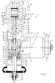
- the level control valve 1 shown in Fig. 1 has a housing 2, which has an axis 3, to the aligned essential Elements of the level control valve 1 are arranged.
- the Housing 2 has an extension 4, the axis 5 at right angles is arranged to the axis 3 and essential for accommodation Elements of an adjustment drive 6 is used.
- the adjustment drive 6 has a lever 7 shown only partially, which with one end inserted into a radial bore of a shaft 8 and is fixed by a fastening screw 9. The not shown other end of the lever 7 is with the vehicle axis connected, while the housing 2 usually with vertically arranged axis 3 connected to the chassis is. But the reverse arrangement is also conceivable.
- adjustment drive 6 also includes an eccentric cam 10, which sits eccentrically in one end face of the shaft 8.
- a connector 11 for a line 12 is provided on the housing 2, about the pressurized air from a reservoir 13 is pending.
- an inflow valve 14, 15 is formed, so that in a storage chamber 16 in the housing 2 supply air is present.
- a double valve body 17 is provided with an inlet seat 18 on the housing side, an inlet valve 17, 18th forms.
- the double valve body 17 is also an outlet seat 19 assigned to a valve lifter 20, so that here an exhaust valve 17, 19 is formed.
- the level control valve 1 is in the Final position shown, d. H. both the inlet valve 17, 18 as well as the outlet valve 17, 19 are closed.
- the valve lifter 20 is sliding and with the help of a seal 21 sealingly displaceable in the housing 2 of the level control valve 1 stored.
- the seal 21 also delimits an inflow chamber 22 around the plunger 20 between the double valve body 17 and the seal 21 is formed. With the inflow chamber are connected via radial channels 23 lines 24 which each to air bellows 25, such as the right and assigned to the left side of the vehicle.
- the adjustment drive 6 engages with its eccentric cam 10 in a slot-like recess 26 of a guide piece 27, which is slidable in alignment with the axis 3 of the housing 2 is mounted so that when the Adjustment drive 6 about the axis 5, the rotational movement of the Eccentric cam 10 in a translatory movement of the Guide piece 27 is deformed in the direction of the axis 3.
- a control piston 28 with a seal 29 slidably mounted to a limited extent In the guide piece 27 is a control piston 28 with a seal 29 slidably mounted to a limited extent.
- the guide piece 27 is also provided with a cover 30, the two seals carries, on the one hand, a control chamber 31 between the lid 30 and guide piece 27 and on the other hand between cover 30 and an extension of the control piston 28 is sealed.
- the lid 30 is stationary via a locking ring 32 in the guide piece 27 fixed and forms a first stop 33 for the control piston 28, the stroke of the control piston 28 relative to the Guide piece 27 limited in one end position.
- the control piston 28 then takes an end position shown in Fig. 1 on when the control chamber 31 is not acted upon. This corresponds to the first vehicle height set.
- the control piston 28 penetrates an opening with a screw shaft 34 35 of the guide piece 27.
- a set screw 37 is screwed onto the screw shaft 34, whose upstanding head on the valve lifter 20 is present.
- the valve lifter 20 is hollow for venting purposes is formed and is formed by a weakly dimensioned spring 38 force downward, so that ultimately the Control piston 28 on the stop 33 of the cover 30 in contact is held.
- the adjusting screw 37 which also can be regarded as part of the valve lifter 20, the effective length of the valve lifter 20 changes, as it were, which makes it possible to set a certain angular position of the lever 7 of the adjustment drive 6 relative to the final position closed inlet valve 17, 18 and closed outlet valve 17, 19 to set.
- the setting via the adjusting screw 37 can be made, for example, in such a way that it is shown Position corresponding to the first vehicle height horizontal position of the lever 7 relative to a vertically arranged Axis 3 of the housing 2 of the level control valve 1 assigned is.
- the control chamber is used to control a second vehicle height 31 ventilated on the guide piece 27.
- a line 39 is on an insert 40 connected which has an axial channel 41 owns and ends in a chamber 42 in the control piston 28.
- a Seal 43 between insert 40 and control piston 28 seals the Chamber 42 to the outside.
- the chamber 42 stands over a bore 44 with the control chamber 31 in connection.
- This final position is what the relative position of the double valve body 17 and the inlet seat 18 and the outlet seat 19, the same Relative position as for the set first vehicle height, now but assigned to a second vehicle height. It therefore appears useful to speak of a single final position despite two vehicle heights adjustable in different ways. It is understood that as a result of the changed effect Length of the valve lifter 20 between the two vehicle heights relative angular position of the lever 7 of the adjustment drive 6 in the second vehicle height is different than the first vehicle height.
- the insert is used to adjust the set screw 37 from the outside 40 in the housing 2 of the level control valve 1 via a polygonal approach 48 rotatably mounted.
- the top end of the insert 40 has a further polygonal attachment 49, which is in a corresponding Counter surface engages on the control piston 28, so that when the insert 40 is rotated from the outside, the control piston also 28 is rotated in the guide piece 27.
- the leader 27 is through the protruding into its recess 26 Eccentric cam 10 prevented from rotating about the axis 3.
- FIG. 2 shows a second embodiment of the level control valve, which in its details on the embodiment of the Fig. 1, referred to the description in this regard can be.
- the control chamber 31 is arranged elsewhere and the Effective surface 47 acts downwards, from which it can be seen that the second vehicle height lower than the first vehicle height is higher while in the embodiment of FIG. 1 when the first vehicle height was arranged.
- a further seal 51 is used to fix the control chamber 31 in a groove not occupied in FIG. 1 with a seal inserted.
- the two seals on the lid turn out to be superfluous or obstructive.
- the bore 44 on the control piston 28 is placed elsewhere here in such a way that it between the seals 29 and 51 opens into the control chamber 31.
- the control piston moves 28 down so that it stops at the stops 33 on ribs comes to rest on the cover 30, whereby the length is effective of the valve lifter 20 and ultimately the second Vehicle height is set here below the first Vehicle height is, so that the vehicle body comparatively has been lowered.
- valve lifter 20 and the control piston 28 as one Unit can be formed in one piece.
- the valve lifter 20 thus passes through the guide piece 27.
- the cover 30 is not stationary on the guide piece 27 supported by a locking ring 32, but via a Thread 53 adjustable relative to the guide piece 27.
- the Rotation of the cover 30 relative to the guide piece 27 is also here via the polygonal attachment 48 on the insert 40, now but transferred to the cover 30.
- a fork 54 provides the non-rotatable connection between the insert 40 and the cover 30 forth. This allows the permissible stroke 45 between the stops 33 and 46 of the control piston 28 can be adjusted, the proportional to the difference between the two vehicle heights. Ultimately can thus the second vehicle height relative to the first Vehicle height can be set.
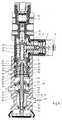
- Fig. 4 shows a section through a level control valve 1 with Height limitation in a more constructive training.
- the Level control valve 1 additionally has a height limitation 55 on.
- the guide piece 27 is extended to a sleeve 56 here and also expanded radially to accommodate the control piston 28.
- the cover 30 is with the help of the locking ring 32 and polygonal outline housed secured against rotation in the sleeve 56.
- the active surface 47 of the control piston 28 is as in FIG. 1 directed upwards.
- a hollow control rod for ventilation purposes 57 belongs to the control of the height limitation 55 Control rod 57 is on cover 30, but not on control piston 28 hung up.
- a cross bolt 58 is used for this purpose.
- the line 39 for the ventilation of the control chamber 31 is here at a connection 59 realized on the side of the housing 2.
- the sleeve 56 has two Seals 60 and 61 to provide air to the control chamber 31 via a bore 62 in the sleeve 56 despite movement of the sleeve To enable 56 together with the guide piece 27.
- the valve lifter 20 is divided here, with a plunger part 63 Guide piece 27 penetrates, the lower end of a Pin 64, which passes through the control piston 28, is supported. It it goes without saying that the plunger 20 and the plunger part 63 also could be integrally formed.
- the guide piece 27 could be integrally formed with the sleeve 56. According to Fig.
- Threaded connection 65 provided a similar setting function like the threaded connection 36 in the exemplary embodiments 1 and 2 come. Here too is the setting the final position to the two vehicle heights possible.
- the Adjustment by means of the threaded connection 65 takes place through Twisting the hollow control rod 57 by means of a polygonal approach 66, the guide piece 27 in turn by the Eccentric cam 10 is held.
- a valve body belongs 67, which is suspended on a spring 68 and the hollow control rod 57 surrounds.
- the spring 68 is supported on a bearing 69, which on housing 2 with the help of cross pins 70 is stationary.
- the bearing 69 is both with seals compared to the hollow control rod 57 as well as that Sealed housing.
- a flow-through chamber 71 limited, the connection to a terminal 72 at which one Line 73 is connected.
- Line 73 is from one Exchangeable charging valve, i.e. a valve for arbitrary lifting and Lowering the vehicle body, in particular for purposes of loading and Unloading connected to a ramp, like this the generic DE 37 16 436 shows.
- a double valve body also belongs to the height limitation 55 76, the one with a housing-fixed inlet seat 77 Shut-off valve 76, 77 for the otherwise open connection forms between lines 73 and 75.
- the double valve body 76 is supported on a spring 78 on the housing side.
- the power the spring 78 is dimensioned weaker than the force of the spring 68.
- the double valve body 76 has the valve body 67 on it facing side a relief seat 79, the diameter is only slightly larger than a vent seat 80 a sleeve-like extension 81, which is by means of a thread 82 is axially adjustable relative to the hollow control rod 57.
- the extension 81 has one for rotation in the thread 82 Polygonal approach 83. It can be seen that when the Polygonal approach 66 and actuated polygonal approach 83 the axial Location of the extension 81 and thus the ventilation seat 80 can be adjusted and adjusted.
- the height limitation 55 in both set vehicle heights is effective in the same way.
- compressed air flows via line 73 into the flow chamber 71 and from there with the shut-off valve 76, 77 open the line 75 to the bellows 25, so that the vehicle body is raised.
- This causes the torsion to twist Lever 7 and the adjustment drive 6 in the sense of opening the Exhaust valve 17, 19.
- this opening can not Impact on the air bellows, as this is caused by the Swap valve is prevented.
- a further reduction in vehicle bodywork in Direction to a previously set vehicle height happens by appropriate venting of line 73 via the shuttle valve.
- the passage chamber 71 is vented in stages, the valve body 67 on the annular surface between the Relief seat 79 and the vent seat 80 is relieved, so that the relief seat 79 slightly from the valve body 67 takes off and so far a pressure equalization between the flow chamber 71 and line 75 takes place.
- a noteworthy This avoids hysteresis.
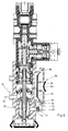
- a height limitation 55 is also provided here, although a quick release valve 84 is switched on in line 75 to the air bellows 25.
- Line 73 is connected to a compressed air supply.
- the connection 74 with the line 91 is here to the shuttle valve.
- a bore 86 leads to the diaphragm 87 of the quick-release valve 84.
- the quick-release valve 84 has its own vent 85, via which the air bellows 25 are quickly vented via check valves 88 when the space 89 located below the double valve body 76 is vented.
- the vent 85 is covered by a flap valve 90.
Landscapes
- Engineering & Computer Science (AREA)
- Mechanical Engineering (AREA)
- Vehicle Body Suspensions (AREA)
Description
- Fig. 1
- einen Querschnitt durch eine erste Ausführungsform des Niveauregelventils mit zwei ansteuerbaren Fahrzeughöhen,
- Fig. 2
- einen Querschnitt durch ein ganz ähnlich wie Fig. 1 aufgebautes Niveauregelventil, bei dem jedoch die zweite Fahrzeughöhe unterhalb der ersten Fahrzeughöhe liegt,
- Fig. 3
- eine weitere Ausführungsform des Niveauregelventils mit einstellbarer Differenz zwischen den beiden Fahrzeughöhen,
- Fig. 4
- ein Niveauregelventil mit Höhenbegrenzung und einstellbarer Abschlußstellung,
- Fig. 5
- eine Detaildarstellung des Niveauregelventils gemäß Fig. 4 zur Verdeutlichung eines Vorsteuerventils in der Höhenbegrenzung und
- Fig. 6
- einen Schnitt durch ein Niveauregelventil mit Höhenbegrenzung, wie in Fig. 4 gezeigt, jedoch mit einem nachgeschalteten Schnellöseventil.


Claims (10)
- Niveauregelventil zum selbsttätigen Konstanthalten der Fahrzeughöhe eines Nutzfahrzeuges mit Luftfederung, mit einem federbelasteten Doppelventilkörper (17), einem Einlaßsitz (18) und einem einen Auslaßsitz (19) für den Doppelventilkörper (17) tragenden und abgedichtet verschiebbaren hohlen Ventilstößel (20), dessen Stellung relativ zum Gehäuse (2) des Niveauregelventils (1) über einen die Fahrzeughöhe abtastenden Verstelltrieb (6) mit Führungsstück (27) und Exzenternocken (10) veränderbar ist, wobei über den Verstelltrieb (6) entsprechend einer Abschlußstellung eine erste Fahrzeughöhe einsteuerbar ist, und mit einem fluchtend zum Ventilstößel (20) vorgesehenen und wahlweise zur Ansteuerung einer zweiten Fahrzeughöhe in einer Steuerkammer (31) beaufschlagbaren Steuerkolben (28), dadurch gekennzeichnet, daß die Steuerkammer (31) in dem Führungsstück (27) des Verstelltriebes (6) angeordnet ist, daß der Steuerkolben (28) in dem Führungsstück (27) abgedichtet und begrenzt verschiebbar gelagert ist, so daß bei Einsteuerung auch der zweiten Fahrzeughöhe der Exzenternocken (10) des Verstelltriebes (6) von einer über den Steuerkolben (28) ausgeübten Stellkraft unbelastet bleibt, und daß der Ventilstößel (20) an dem Steuerkolben (28) abgestützt ist.
- Niveauregelventil nach Anspruch 1, dadurch gekennzeichnet, daß das Führungsstuck (27) des Verstelltriebes (6) nach der dem Einlaßsitz (18) abgekehrten Seite verlängert und zu einer Hülse (56) ausgeformt ist, und daß der Steuerkolben (28) in der Hülse (56) gelagert ist.
- Niveauregelventil nach Anspruch 2, dadurch gekennzeichnet, daß die Hülse (56) einen den Hub (45) des Steuerkolbens (28) in der Hülse (56) festlegenden Deckel (30) aufweist.
- Niveauregelventil nach Anspruch 3, dadurch gekennzeichnet, daß der Deckel (30) über ein Gewinde (53) in der Hülse (56) verstellbar und damit der Hub (45) des Steuerkolbens (28) für die Einsteuerung der beiden Fahrzeughöhen einstellbar ist.
- Niveauregelventil nach den Ansprüchen 1 bis 4, dadurch gekennzeichnet, daß zwischen Steuerkolben (28) und Ventilstößel (20) eine Stellschraube (37) zum Einstellen der Abschlußstellung der beiden Fahrzeughöhen vorgesehen ist.
- Niveauregelventil nach den Ansprüchen 1 bis 4, dadurch gekennzeichnet, daß der Steuerkolben (28) und der Ventilstößel (20) eine Baueinheit bilden.
- Niveauregelventil nach einem oder mehreren der Ansprüche 1 bis 6, dadurch gekennzeichnet, daß zur Realisierung einer Höhenbegrenzung (55) eine mit dem Führungsstück (27) verbundene hohle Steuerstange (57) vorgesehen ist, die einen Entlüftungssitz (80) trägt, dem ein ringartiger, die Steuerstange (57) umgebender federnd aufgehängter Ventilkörper (67) zugeordnet ist.
- Niveauregelventil nach Anspruch 7, dadurch gekennzeichnet, daß ein im Gehäuse (2) federnd aufgehängter Doppelventilkörper (76) vorgesehen ist, der mit einem gehäusefesten Einlaßsitz (77) ein Absperrventil (76, 77) für eine zu den Luftfederbälgen (25) führende Leitung (75) und mit dem Ventilkörper (67) ein Vorsteuerventil (67, 79) bildet.
- Niveauregelventil nach Anspruch 7 oder 8, dadurch gekennzeichnet, daß die axiale Lage des Entlüftungssitzes (80) und damit die gemeinsame Höhenbegrenzung (55) relativ zu der Steuerstange (57) über ein Gewinde (82) einstellbar ist.
- Niveauregelventil nach einem oder mehreren der Ansprüche 3 bis 9, dadurch gekennzeichnet, daß zwischen dem Führungsstück (27) und der Hülse (56) eine Gewindeverbindung (99) vorgesehen ist, und daß die Steuerstange (57) mit dem Deckel (30) und der Hülse (56) drehfest verbunden ist.
Applications Claiming Priority (2)
| Application Number | Priority Date | Filing Date | Title |
|---|---|---|---|
| DE19607619A DE19607619C1 (de) | 1996-02-29 | 1996-02-29 | Niveauregelventil zum selbsttätigen Konstanthalten der Fahrzeughöhe eines Nutzfahrzeuges mit Luftfederung |
| DE19607619 | 1996-02-29 |
Publications (2)
| Publication Number | Publication Date |
|---|---|
| EP0792762A1 EP0792762A1 (de) | 1997-09-03 |
| EP0792762B1 true EP0792762B1 (de) | 1998-08-05 |
Family
ID=7786740
Family Applications (1)
| Application Number | Title | Priority Date | Filing Date |
|---|---|---|---|
| EP97101748A Expired - Lifetime EP0792762B1 (de) | 1996-02-29 | 1997-02-05 | Niveauregelventil zum selbsttätigen Konstanthalten der Fahrzeughöhe eines Nutzfahrzeuges mit Luftfederung |
Country Status (4)
| Country | Link |
|---|---|
| US (1) | US5871217A (de) |
| EP (1) | EP0792762B1 (de) |
| DE (2) | DE19607619C1 (de) |
| ES (1) | ES2120813T3 (de) |
Families Citing this family (12)
| Publication number | Priority date | Publication date | Assignee | Title |
|---|---|---|---|---|
| DE19636002C1 (de) * | 1996-09-05 | 1997-10-16 | Grau Gmbh | Niveauregelventil zum selbsttätigen Konstanthalten der Fahrzeughöhe eines Nutzfahrzeuges mit Luftfederung |
| AU3549599A (en) * | 1998-04-07 | 1999-10-25 | P. Dennis McNeely | A suspension and a dynamic load-compensating fluid spring therefor |
| US6408900B1 (en) | 2001-03-29 | 2002-06-25 | Salco Products, Inc. | Load distribution deflector |
| US6564834B2 (en) | 2001-03-29 | 2003-05-20 | Salco Products, Inc. | Load distribution deflector |
| KR100422551B1 (ko) * | 2001-10-08 | 2004-03-11 | 현대자동차주식회사 | 자동차의 공기현가장치 |
| DE10154778C1 (de) | 2001-11-08 | 2002-12-12 | Haldex Brake Prod Gmbh | Niveauregelventil zum selbsttätigen Konstanthalten der Fahrzeughöhe eines Nutzfahrzeuges mit Luftfederung |
| KR100422557B1 (ko) | 2001-11-08 | 2004-03-11 | 현대자동차주식회사 | 자동차의 공기현가장치 |
| KR100471811B1 (ko) | 2001-12-14 | 2005-03-08 | 현대자동차주식회사 | 자동차의 가변형 레벨링 밸브 장치 |
| US7959173B1 (en) * | 2007-09-26 | 2011-06-14 | Alkon Corporation | Air distribution apparatus |
| CN102706300B (zh) * | 2012-06-11 | 2014-10-22 | 卓越(苏州)自动化设备有限公司 | 高度检测装置 |
| DE102012014349B4 (de) * | 2012-07-19 | 2020-12-31 | Wabco Gmbh | Luftfederventil |
| GB2637321A (en) * | 2024-01-16 | 2025-07-23 | Haldex Ab | A valve assembly |
Family Cites Families (8)
| Publication number | Priority date | Publication date | Assignee | Title |
|---|---|---|---|---|
| US3006657A (en) * | 1957-12-09 | 1961-10-31 | Bendix Westinghouse Automotive | Height control and leveling valve for air springs |
| DE1144125B (de) * | 1961-07-13 | 1963-02-21 | Boge Gmbh | Drehschiebergesteuerter Hoehenregler zur Regelung von mit einem Fluid arbeitenden Federungen, insbesondere fuer Kraftfahrzeuge |
| FR2125217B1 (de) * | 1971-02-19 | 1975-01-17 | Saviem | |
| DE2318535C3 (de) * | 1973-04-12 | 1981-11-12 | Knorr-Bremse GmbH, 8000 München | Nieveauregelventil für Luftfederungen von Fahrzeugen, insbesondere Container-Fahrzeugen |
| DE2601665A1 (de) * | 1976-01-17 | 1977-07-21 | Knorr Bremse Gmbh | Luftfederungsventil fuer fahrzeuge |
| DE3716436A1 (de) * | 1987-05-16 | 1988-12-01 | Graubremse Gmbh | Niveauregelventil mit hoehenbegrenzung |
| JPH04238713A (ja) * | 1991-01-11 | 1992-08-26 | Hino Motors Ltd | レベリングバルブ |
| JP2663053B2 (ja) * | 1991-01-11 | 1997-10-15 | 日野自動車工業株式会社 | レベリングバルブ |
-
1996
- 1996-02-29 DE DE19607619A patent/DE19607619C1/de not_active Expired - Fee Related
-
1997
- 1997-02-05 DE DE59700007T patent/DE59700007D1/de not_active Expired - Lifetime
- 1997-02-05 EP EP97101748A patent/EP0792762B1/de not_active Expired - Lifetime
- 1997-02-05 ES ES97101748T patent/ES2120813T3/es not_active Expired - Lifetime
- 1997-02-20 US US08/802,751 patent/US5871217A/en not_active Expired - Lifetime
Also Published As
| Publication number | Publication date |
|---|---|
| DE59700007D1 (de) | 1998-09-10 |
| ES2120813T3 (es) | 1998-11-01 |
| DE19607619C1 (de) | 1997-07-31 |
| US5871217A (en) | 1999-02-16 |
| EP0792762A1 (de) | 1997-09-03 |
Similar Documents
| Publication | Publication Date | Title |
|---|---|---|
| DE3034103C2 (de) | ||
| DE1225510B (de) | Niveauventilanordnung fuer jeweils einen balgfoermigen Luftfederungskoerper von Fahrzeugen | |
| DE19607619C1 (de) | Niveauregelventil zum selbsttätigen Konstanthalten der Fahrzeughöhe eines Nutzfahrzeuges mit Luftfederung | |
| DE1859132U (de) | Ventil fuer fahrzeug-druckmittelbremsen. | |
| DE1125784B (de) | Fahrzeug-Aufhaengevorrichtung mit einer zwischen Fahrzeug- und Achsenteil liegenden Gasfeder und Gassteuer-Ventileinrichtungen | |
| EP0188707B1 (de) | Niveauregelventil mit Höhenbegrenzung | |
| DE1121943B (de) | Fahrzeug-Aufhaengevorrichtung mit einer zwischen einen Fahrzeugteil und einen Achsenteil geschalteten Gasfeder und Ventileinrichtungen | |
| DE1505608C3 (de) | ||
| DE3716436C2 (de) | ||
| DE2918032C2 (de) | Relaisventil für druckmittelbeaufschlagte Bremsanlagen an Kraftfahrzeugen und Anhängerfahrzeugen | |
| DE3722306C2 (de) | ||
| DE1192534B (de) | Bremsdruckregler fuer Fahrzeuge, insbesondere Kraftfahrzeuge | |
| EP0407751B1 (de) | Relaisventil für Druckluftbremsanlagen in Kraftfahrzeugen | |
| DE3008239C2 (de) | ||
| DE1455593A1 (de) | Einrichtung zur Einstellung des Bremsverstaerkers fuer hydraulische Bremsen | |
| DE1079968B (de) | Lastabhaengiges Steuerventil fuer Luftfedern bei Kraftfahrzeugen | |
| DE2318535C3 (de) | Nieveauregelventil für Luftfederungen von Fahrzeugen, insbesondere Container-Fahrzeugen | |
| DE4414868C1 (de) | Steueranlage zum willkürlichen Heben und Senken des Fahrzeugaufbaus von luftgefederten Fahrzeugen | |
| DE2104539A1 (de) | Automatisch lastabhängiger Bremskraftregler | |
| DE3903457C2 (de) | ||
| EP0827850B1 (de) | Niveauregelventil zum selbsttätigen Konstanthalten der Fahrzeughöhe eines Nutzfahrzeuges mit Luftfederung | |
| EP0332854B1 (de) | Bremsventil, insbesondere ein Führerbremsventil und ein lastabhängiges Bremsventil zur Steuerung des Bremsleitungsdruckes | |
| DE2501070B2 (de) | Zweileitungs-druckluftbremsanlage fuer kraftfahrzeuge mit anhaenger, mit einem anhaengersteuerventil und einem sperrventil | |
| DE3734618C1 (en) | Manually operatable axle lifting valve for multi-axle motor vehicles, trailer vehicles and the like | |
| DE1630189A1 (de) | Steuer- und Bremsdruckregelventil fuer Anhaenger-Druckluftbremsanlagen |
Legal Events
| Date | Code | Title | Description |
|---|---|---|---|
| PUAI | Public reference made under article 153(3) epc to a published international application that has entered the european phase |
Free format text: ORIGINAL CODE: 0009012 |
|
| AK | Designated contracting states |
Kind code of ref document: A1 Designated state(s): DE ES FR GB IT |
|
| 17P | Request for examination filed |
Effective date: 19970718 |
|
| GRAG | Despatch of communication of intention to grant |
Free format text: ORIGINAL CODE: EPIDOS AGRA |
|
| 17Q | First examination report despatched |
Effective date: 19971111 |
|
| GRAG | Despatch of communication of intention to grant |
Free format text: ORIGINAL CODE: EPIDOS AGRA |
|
| GRAH | Despatch of communication of intention to grant a patent |
Free format text: ORIGINAL CODE: EPIDOS IGRA |
|
| GRAH | Despatch of communication of intention to grant a patent |
Free format text: ORIGINAL CODE: EPIDOS IGRA |
|
| ITF | It: translation for a ep patent filed | ||
| GRAA | (expected) grant |
Free format text: ORIGINAL CODE: 0009210 |
|
| AK | Designated contracting states |
Kind code of ref document: B1 Designated state(s): DE ES FR GB IT |
|
| GBT | Gb: translation of ep patent filed (gb section 77(6)(a)/1977) |
Effective date: 19980810 |
|
| REF | Corresponds to: |
Ref document number: 59700007 Country of ref document: DE Date of ref document: 19980910 |
|
| REG | Reference to a national code |
Ref country code: ES Ref legal event code: FG2A Ref document number: 2120813 Country of ref document: ES Kind code of ref document: T3 |
|
| ET | Fr: translation filed | ||
| PLBE | No opposition filed within time limit |
Free format text: ORIGINAL CODE: 0009261 |
|
| STAA | Information on the status of an ep patent application or granted ep patent |
Free format text: STATUS: NO OPPOSITION FILED WITHIN TIME LIMIT |
|
| 26N | No opposition filed | ||
| REG | Reference to a national code |
Ref country code: GB Ref legal event code: IF02 |
|
| REG | Reference to a national code |
Ref country code: FR Ref legal event code: TP Ref country code: FR Ref legal event code: CD |
|
| REG | Reference to a national code |
Ref country code: GB Ref legal event code: 732E |
|
| PGFP | Annual fee paid to national office [announced via postgrant information from national office to epo] |
Ref country code: ES Payment date: 20080221 Year of fee payment: 12 |
|
| PGFP | Annual fee paid to national office [announced via postgrant information from national office to epo] |
Ref country code: IT Payment date: 20080228 Year of fee payment: 12 |
|
| REG | Reference to a national code |
Ref country code: ES Ref legal event code: FD2A Effective date: 20090206 |
|
| PG25 | Lapsed in a contracting state [announced via postgrant information from national office to epo] |
Ref country code: ES Free format text: LAPSE BECAUSE OF NON-PAYMENT OF DUE FEES Effective date: 20090206 |
|
| PG25 | Lapsed in a contracting state [announced via postgrant information from national office to epo] |
Ref country code: IT Free format text: LAPSE BECAUSE OF NON-PAYMENT OF DUE FEES Effective date: 20090205 |
|
| REG | Reference to a national code |
Ref country code: FR Ref legal event code: PLFP Year of fee payment: 20 |
|
| PGFP | Annual fee paid to national office [announced via postgrant information from national office to epo] |
Ref country code: DE Payment date: 20151224 Year of fee payment: 20 |
|
| PGFP | Annual fee paid to national office [announced via postgrant information from national office to epo] |
Ref country code: GB Payment date: 20160222 Year of fee payment: 20 Ref country code: FR Payment date: 20160222 Year of fee payment: 20 |
|
| REG | Reference to a national code |
Ref country code: DE Ref legal event code: R082 Ref document number: 59700007 Country of ref document: DE Representative=s name: REHBERG HUEPPE + PARTNER PATENTANWAELTE PARTG , DE Ref country code: DE Ref legal event code: R081 Ref document number: 59700007 Country of ref document: DE Owner name: HALDEX BRAKE PRODUCTS AKTIEBOLAG, SE Free format text: FORMER OWNER: HALDEX BRAKE PRODUCTS GMBH, 69123 HEIDELBERG, DE |
|
| REG | Reference to a national code |
Ref country code: DE Ref legal event code: R071 Ref document number: 59700007 Country of ref document: DE |
|
| REG | Reference to a national code |
Ref country code: GB Ref legal event code: 732E Free format text: REGISTERED BETWEEN 20170112 AND 20170118 |
|
| REG | Reference to a national code |
Ref country code: FR Ref legal event code: TP Owner name: HALDEX BRAKE PRODUCTS AKTIEBOLAG, SE Effective date: 20170123 |
|
| REG | Reference to a national code |
Ref country code: GB Ref legal event code: PE20 Expiry date: 20170204 |
|
| PG25 | Lapsed in a contracting state [announced via postgrant information from national office to epo] |
Ref country code: GB Free format text: LAPSE BECAUSE OF EXPIRATION OF PROTECTION Effective date: 20170204 |