EP0792811A1 - Machine de déballage de rouleaux, spécialement de rouleaux de papier d'imprimerie - Google Patents
Machine de déballage de rouleaux, spécialement de rouleaux de papier d'imprimerie Download PDFInfo
- Publication number
- EP0792811A1 EP0792811A1 EP97100869A EP97100869A EP0792811A1 EP 0792811 A1 EP0792811 A1 EP 0792811A1 EP 97100869 A EP97100869 A EP 97100869A EP 97100869 A EP97100869 A EP 97100869A EP 0792811 A1 EP0792811 A1 EP 0792811A1
- Authority
- EP
- European Patent Office
- Prior art keywords
- winding
- axis
- mandrels
- roller
- machine according
- Prior art date
- Legal status (The legal status is an assumption and is not a legal conclusion. Google has not performed a legal analysis and makes no representation as to the accuracy of the status listed.)
- Withdrawn
Links
- 238000004804 winding Methods 0.000 claims abstract description 46
- 238000006073 displacement reaction Methods 0.000 claims abstract 2
- 239000000463 material Substances 0.000 claims description 2
- 238000012856 packing Methods 0.000 claims 1
- 238000004806 packaging method and process Methods 0.000 description 3
- 239000002699 waste material Substances 0.000 description 2
- 238000004026 adhesive bonding Methods 0.000 description 1
- 239000002390 adhesive tape Substances 0.000 description 1
- 238000013459 approach Methods 0.000 description 1
- 238000011161 development Methods 0.000 description 1
- 230000018109 developmental process Effects 0.000 description 1
- 239000010893 paper waste Substances 0.000 description 1
- 229920002635 polyurethane Polymers 0.000 description 1
- 239000004814 polyurethane Substances 0.000 description 1
- 238000012958 reprocessing Methods 0.000 description 1
- 230000001360 synchronised effect Effects 0.000 description 1
Images



Classifications
-
- B—PERFORMING OPERATIONS; TRANSPORTING
- B65—CONVEYING; PACKING; STORING; HANDLING THIN OR FILAMENTARY MATERIAL
- B65B—MACHINES, APPARATUS OR DEVICES FOR, OR METHODS OF, PACKAGING ARTICLES OR MATERIALS; UNPACKING
- B65B69/00—Unpacking of articles or materials, not otherwise provided for
- B65B69/0033—Unpacking of articles or materials, not otherwise provided for by cutting
Definitions
- the invention relates to an unpacking machine for rolls, in particular printing paper rolls, which have a cover, in particular made of packaging paper, according to the preamble of claim 1.
- Newsprint and other paper intended for printing on rotary machines is usually supplied in the form of packaged rolls.
- the packaging that has to be removed in the print shop usually consists of circular covers on both faces of each individual roll and a multi-layer wrapping of wrapping paper wrapped around the roll.
- Unpacking machines of the type mentioned are intended to strip and dispose of rolls which have already been freed from their front covers or have been supplied without such covers, from their essentially cylindrical sheath.
- Such unpacking machines usually have a machine frame on which a radial slide can be adjusted according to the diameter of a roll to be unpacked.
- the roller is centered with respect to the machine frame, for example in that its outer surface has been placed on a pair of axially parallel rollers.
- the unpacking machine also includes a cutting device with a knife carriage, which can be moved along a longitudinal guide along a surface line of the roll over its length, around the one consisting of wrapping paper or the like Slit open the sheath and, if necessary, one or more layers of printing paper, so-called "white” paper.
- casing In order to dispose of this waste, which is summarized below under the name "casing", it is necessary to peel the casing from the roll, to transport it away and to save it for reprocessing in a paper mill.
- a state-of-the-art unpacking machine of the type mentioned is known from EP 0 634 329 A1.
- a winding device with a winding axis parallel to the roll axis is arranged at a distance from the space provided for the roll.
- the winding device has a pair of winding mandrels, the length of which is approximately as long as the length of the largest roll occurring.
- the winding thus formed from the sleeve is finally gripped by two rollers which can be moved toward one another in the manner of pliers, each of which can be driven in rotation about a roller axis normal to the winding axis and has pointed radial projections. These rollers pull the roll resulting from the sheath from the mandrels in their longitudinal direction.
- the space requirement of this arrangement in the longitudinal direction of the mandrels is a multiple of the largest occurring roll length.
- the invention has for its object to make the devices required for disposing of the sleeves space-saving.
- a wire removal machine for waste paper bales or the like which has a cutter bar for cutting wires wrapped around a bale and two sets of winding mandrels. These can be driven synchronously around a common winding axis parallel to the cutter bar, along which they can be adjusted in opposite directions symmetrically to a normal plane normal to the winding axis, in order to detect the wires by mutual approximation, wind them up and then move them apart again, the wound wires are stripped into a space that is released between the mandrel sets. While winding the wires, the mandrel sets overlap so that one of them can drive the other.
- a space between the winding mandrel sets is thus only free after winding has been completed. Before the winding mandrel sets are moved apart, no device for holding the coiled wires can therefore intervene between them.
- a stripping plate is provided, through which the winding mandrels of a set extend, and which can be displaced in relation to these winding mandrels in the direction of the intermediate space.
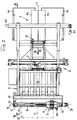
- the unpacking machine shown has a centering device 1, which is intended to arrange a roll R of packaged printing paper with a horizontal axis A in a vertical reference plane B, normal to a longitudinal center plane C of the unpacking machine.
- the roll R has a sleeve D, which consists for example of packaging paper and is to be removed.
- the centering device 1 is arranged below a portal-like front or starting area of a machine frame 2, which carries all the devices required for removing the casing D, namely a gripping device 3 for forming a bulge in the casing D, a cutting device 4 for cutting open the casing D along a generatrix , i.e.
- a peeling device 5 for peeling the cut casing D from the roll R
- a winding device 6 for space-saving winding of the peeled casing D
- a pivoting device 7 for pivoting the wound casing D into an axis A normal position
- a squeezing device 8 for squeezing the wrapped sleeve D
- a sorting device 9 for separately disposing of the sleeve D on the one hand and adjoining printing paper, so-called white paper, on the other hand.
- white paper so-called white paper
- the centering device 1 includes a pair of support rollers 10, which are mounted in a common horizontal plane parallel to each other on both sides of a conveyor 11, and at least one of which can be driven in rotation.
- a roller R can each be conveyed in the direction of its axis A, while the support rollers 10 assume a lowered position indicated by dash-dotted lines in FIG.
- the two support rollers 10 can be raised together with the roller R into their operating position drawn with full lines in FIG. 1; the role is R then rotatable about its axis A, which lies reliably in the reference plane B; this is the vertical center plane between the two support rollers 10.
- the machine frame 2 has, above the centering device 1, a horizontal support 12 which is parallel to the reference plane B and has an upwardly projecting support 13 attached to each of its two ends.
- a radial slide 14 is guided up and down in the reference plane B, that is to say radially to the roller R; its radial movements are ensured by two motors 15 synchronized with one another, e.g. Electric motors, which are arranged on one of the two supports 13.
- the radial slide 14 is designed like a frame and has a horizontal guide 16 lying in the reference plane B, on which a pliers slide 17 is guided horizontally and is adjustable parallel to the axis A by means of a motor 18, for example a piston-cylinder unit.
- the pliers slide 17 is part of the gripping device 3; on it a pair of two-armed levers 19 are mounted, which together form a gripper 20 and each have a jaw 21 at their lower ends made of a material with a high coefficient of friction, for example made of polyurethane.
- the upper ends of the two levers 19 are connected by a toggle lever arrangement 22 to a motor, which can be a pneumatic piston-cylinder unit, for example.
- the cutting device 4 includes a longitudinal guide 24, which is also located in the reference plane B and normally extends essentially parallel to the axis A of the roller R.
- the longitudinal guide 24 is arranged essentially below the radial slide 14 and is pivotably mounted on the radial slide 14 at one of its ends by means of a pivot bearing 25 in the reference plane B.
- the longitudinal guide 24 is connected to the radial slide 14 by a servomotor 26, preferably a digitally controllable electric motor.
- the servomotor 26 is controlled by a sensor 27 on the radial slide 14 can be moved back and forth normally by means of a motor 28 to the reference plane B and vertically adjustable by means of a motor 29.
- a knife carriage 30 can be moved back and forth by means of a motor 31 between an initial position shown on the right in FIG. 3 and an indicated end position. The distance that the knife carriage 30 travels between these two positions is somewhat longer than the length of the longest occurring roll R.
- the position of the bulge depending on the diameter of the roller R is located by the sensor 27 and then the motor 31 is switched on so that it moves the knife carriage 30 from its starting position into its end position.
- a guide blade penetrates the bulge of the casing D and guides a first knife inside the bulge over any irregularities in the roll R.
- the envelope D and the outermost layer of white paper generally together with it, form the bulge on the whole Cut the length of the sleeve D from the inside out.
- the layer of white paper left at the top under the bulge is cut open radially from the outside inwards by a second knife. This is generally necessary to ensure that the top layer of white paper, which has mostly become unusable due to gluing, is removed together with the sleeve D.
- the peeling device 5 has the task, on the one hand, of peeling the casing D and one or more adjoining layers of white paper, after they have been cut in the manner described along an upper surface line of the roll R, from the remaining usable roll R, but on the other hand to prevent the cut sleeve D from loosening prematurely, making the intended disposal difficult.
- the waste to be disposed of may have white paper in addition to the envelope D - and in some cases also in its place - or may consist entirely of such paper.
- the peeling device 5 includes a peeling roller 50 which can be driven in rotation and which is arranged normal to the vertical longitudinal center plane C of the machine, that is to say horizontally and parallel to the axis A, behind the roller R, to the right of it in accordance with FIG.
- the peeling roller 15 is mounted in a roller carrier 51, which in turn is pivotably mounted in the machine frame 2 about an axis 52 which is normal to the longitudinal center plane C, that is to say parallel to the peeling roller 50.
- the roller carrier 51 is indicated in FIG. 1 by dash-dotted lines in a position in which it rests on the smallest roll R to prevent its casing D from prematurely sinking after being cut open and then to peel it off the roll.
- the roller carrier 51 together with the peeling roller 15 is shown in full lines in FIG. 1 in a position for further conveying the peeled casing D.
- the peeling device 5 is assigned a guide 55 which begins in the area below the roller carrier 51 and from there extends obliquely upwards in a plane normal to the longitudinal center plane C.
- the guide 55 is formed by a belt conveyor which, according to FIG. 2, has a plurality of parallel belts which can be driven obliquely upward in the direction of the arrow.
- the peeling device 5 works as follows:
- the peeling roller 50 can be supported in that the guide 55 according to the illustrated embodiment is formed by a conveyor operating in the same direction.
- an upper conveyor 56 begins, which extends parallel to the guide 55 and, for example by means of a spring arrangement, is elastically pretensioned towards the latter.
- the casing D is now conveyed upward together by the two conveyors 55 and 56 and arrives in a feed gap which extends obliquely upward as an extension of the conveyors 55 and 56 and is formed between two plate-shaped components 57 and 58, of which the lower component 58 for changing the gap width is pivotable by means of a motor 59.
- the sheath D reaches the winding device 6, which has two reels 60 arranged symmetrically to the longitudinal center plane C.
- the two reels 60 are normal to the longitudinal center plane C, always symmetrical about the latter, and can be moved toward and away from one another.
- the two reels 60 are connected to a motor 62 via a common gear 61.
- the gear 61 has a circulating belt, with the two strands of which one of the two reels 60 is connected.
- the motor 62 is shown as a pneumatic piston-cylinder unit.
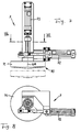
- Each of the two reels 60 has two winding mandrels 63, which are arranged in a fork-like manner on each side of a winding axis 64 and, when the reels 60 are at a standstill, assume the position shown in FIG and to the longitudinal direction of the plate-shaped components 57 and 58 normal plane. Both reels 60 can be driven in rotation by a motor 66 about their common winding axis 64 via a gear 65.
- the two reels 60 are each set at the beginning of a working cycle in such a way that the incoming sheath D can be pushed through the gaps between the mandrels 63 that belong together in pairs, without having too much lateral play between the reels.
- 6 shows in dash-dotted lines the position of the two winding mandrels 64 of the left reel 60 that is closest to the vertical longitudinal center plane C; The same applies to the right reel.
- the dash-dotted setting is intended for winding packages D that come from rolls R with the smallest occurring length. In this setting, there is still an axial distance between the two opposing pairs of mandrels 63, which is sufficient for engaging the pivoting device 7 described in more detail below.
- the pivoting device 7 includes a lower clamping body 67, which can be freely rotated about an axis hereinafter referred to as pivot axis 68, lying in the longitudinal center plane C and approximately normal to the conveying direction of the two conveyors 55 and 56, and by means of a motor 69, for example a pneumatic piston-cylinder unit. along this axis can be raised from its rest position shown in Figure 5 into a clamping position.
- the lower clamping body 67 has the shape of a flat cone, the tip of which lies at least approximately on the winding axis 64 in the clamping position.
- the lower clamping body 67 is part of a plier-like clamping device 70; this also includes an upper clamping body 71, which also has the shape of a flat cone, faces the lower clamping body 67 coaxially and has the same pivot axis 68.
- the upper clamping body 71 can be rotated back and forth by 90 ° about the pivot axis 68 by means of a motor 72, which is drawn as a pneumatic piston-cylinder unit.
- the upper clamping body 71 together with its motor 72 can be lowered by means of a further motor 73, expediently also a piston-cylinder unit, from its rest position shown in full lines in FIG. 7 along the pivot axis 68 into a clamping position indicated by dash-dotted lines.
- the force that can be generated by motor 73 is noticeably less than that which can be generated by motor 69; the lower clamping body 67 thus reaches the clamping position described in any case; the clamping position reached by the upper clamping body 71, on the other hand, depends on the thickness of the winding which has arisen from the sleeve D between the two clamping bodies 67 and 71.
- the mandrels 63 are at a sufficiently large distance from the longitudinal center plane C so that they do not get between the clamping bodies 67 and 71 when they are in their clamping position. Therefore, the two clamping bodies 67 and 71 only press the wrap formed from the sleeve D flat between them and hold it in place.
- the motor 62 is switched on, so that the two reels 60 are moved apart until all the mandrels 63 from the Sheath D formed axially pulled out. Subsequently, the motor 72 is actuated so that the upper clamping body 71 makes a quarter turn in which the lower clamping body 67 also participates.
- the winding is pivoted through 90 ° about the pivot axis 68.
- the winding formed by the casing D is aligned at least approximately in the longitudinal center plane C of the machine, so that it can then be conveyed further in a space-saving manner.
- the now front half of the wound cover D enters a gap 74 belonging to the squeezing device 8, which is delimited at the bottom by a lower guide 75.
- the lower guide 75 is formed by a stationary belt conveyor which can be driven by a motor 76 in such a way that the wound cover D is conveyed further obliquely upwards in the longitudinal center plane C at right angles from the pivot axis 68, according to FIG right.
- a squeeze roller 77 is arranged, which is freely rotatable about an axis normal to the longitudinal center plane C.
- the gap 74 is delimited by an upper guide 78; this is also formed by a conveyor which extends obliquely upward at approximately a right angle from the pivot axis 68 and can be driven by its own motor 79.
- an upper squeeze roller 80 is also mounted normal to the longitudinal center plane C; this squeeze roller 80 is adjustable in the longitudinal direction of the upper guide 78.
- the upper guide 78 is mounted with a bearing 81 arranged in its initial region, on the left in FIG. 1, with an axis normal to the longitudinal central plane C on the machine frame 2 and additionally connected to it by a motor 82, for example a pneumatic piston-cylinder unit, such that the inclination the upper guide 78 can be changed between the upper position drawn in full lines in FIG. 1 and the lower position indicated by dash-dotted lines.
- a motor 82 for example a pneumatic piston-cylinder unit
- the upper guide 78 assumes its upper end position, so that the gap 74 between the two guides 75 and 78 has its greatest possible height and the pivoting of the wound cover D is not hindered. Then the upper guide 78 is lowered and the conveyors, which form the two guides 75 and 78, are started. As a result, the wrapped sleeve D is compressed and conveyed further in its new longitudinal direction, at right angles to the pivot axis 68, whereby it is moved between the two squeeze rollers 77 and 80 and is thereby squeezed flat. The upper squeeze roller 80 is adjusted with respect to the lower squeeze roller 77 so that the wrapped sleeve D is deflected somewhat downward in an approximately horizontal direction of movement as it passes between the two squeeze rollers.
- the sorting device 9 connects to the squeezing device 8.
- This includes a guide 83 which is arranged normal to the longitudinal center plane C and is designed similar to a crane's track.
- a slide 84 can be moved back and forth on the guide 83 normal to the longitudinal center plane C by means of a motor 85.
- the carriage 84 carries two trough halves 86, which can be moved apart by means of a motor 87 from a closed position drawn in full lines in FIG. 4, in which they form a trough 88 which is closed at the bottom.
- the closed trough 88 is normally in a middle position, as shown in FIG. 4 with solid lines.
- the trough 88 can be moved from this middle position into one of two ejection positions by means of a further motor 89.
- Such a discharge position is indicated on the left in FIG. 4 with dashed lines.
- a container 90 for sleeves D is arranged below this discharge position, while a container 91 for white paper is arranged below the other
- a wrap which either consists essentially of wrapping paper or white paper subsequently removed from the roll R, enters the closed trough.
- the type of paper is determined by a sensor that responds to the color of the paper. Accordingly, the closed trough 88, relative to FIG. 4, is moved to the right or to the left, and there the trough halves 86 are moved apart, so that the wrap formed by the casing D is placed in one or the other of the two containers 90, depending on the nature of the paper and 91 is dropped.
- an adhesive tape dispenser 92 can be arranged above the peeling device 5, with which the uppermost layer of white paper remaining on the roll R can be attached so that it does not become detached on the way to a rotary printing machine or the like.
Landscapes
- Engineering & Computer Science (AREA)
- Mechanical Engineering (AREA)
- Control And Other Processes For Unpacking Of Materials (AREA)
Applications Claiming Priority (2)
| Application Number | Priority Date | Filing Date | Title |
|---|---|---|---|
| DE19607508 | 1996-02-28 | ||
| DE1996107508 DE19607508C1 (de) | 1996-02-28 | 1996-02-28 | Auspackmaschine für Rollen, insbes. Druckpapierrollen |
Publications (1)
| Publication Number | Publication Date |
|---|---|
| EP0792811A1 true EP0792811A1 (fr) | 1997-09-03 |
Family
ID=7786674
Family Applications (1)
| Application Number | Title | Priority Date | Filing Date |
|---|---|---|---|
| EP97100869A Withdrawn EP0792811A1 (fr) | 1996-02-28 | 1997-01-21 | Machine de déballage de rouleaux, spécialement de rouleaux de papier d'imprimerie |
Country Status (2)
| Country | Link |
|---|---|
| EP (1) | EP0792811A1 (fr) |
| DE (1) | DE19607508C1 (fr) |
Families Citing this family (2)
| Publication number | Priority date | Publication date | Assignee | Title |
|---|---|---|---|---|
| DE102004043102A1 (de) * | 2004-09-07 | 2006-03-09 | Man Roland Druckmaschinen Ag | System und Verfahren zum Auspacken einer Druckpapierrole |
| CN102849283A (zh) * | 2012-08-30 | 2013-01-02 | 金川集团股份有限公司 | 一种切割水淬渣包的方法 |
Citations (1)
| Publication number | Priority date | Publication date | Assignee | Title |
|---|---|---|---|---|
| EP0634329A1 (fr) | 1993-07-14 | 1995-01-18 | Enterprises International, Inc. | Machine automatique et procédé pour enlever la feuille d'enveloppement d'un rouleau |
Family Cites Families (1)
| Publication number | Priority date | Publication date | Assignee | Title |
|---|---|---|---|---|
| DE4200217C2 (de) * | 1992-01-08 | 1995-10-05 | Stuehlen Hebe U Foerdertechnik | Entdrahtungsmaschine |
-
1996
- 1996-02-28 DE DE1996107508 patent/DE19607508C1/de not_active Expired - Fee Related
-
1997
- 1997-01-21 EP EP97100869A patent/EP0792811A1/fr not_active Withdrawn
Patent Citations (1)
| Publication number | Priority date | Publication date | Assignee | Title |
|---|---|---|---|---|
| EP0634329A1 (fr) | 1993-07-14 | 1995-01-18 | Enterprises International, Inc. | Machine automatique et procédé pour enlever la feuille d'enveloppement d'un rouleau |
Also Published As
| Publication number | Publication date |
|---|---|
| DE19607508C1 (de) | 1997-07-03 |
Similar Documents
| Publication | Publication Date | Title |
|---|---|---|
| DE69217917T2 (de) | Auswickelvorrichtung mit Schwenkarmen und Greifern | |
| DE69010058T2 (de) | Verfahren und Vorrichtung zum Schneiden und Schweissen einer Verpackungsfolie. | |
| DE2847556A1 (de) | Revolverkopf-aufwickelmaschine fuer bandfoermiges material | |
| DE3723827C2 (fr) | ||
| DE69505334T2 (de) | Produktionsmaschine mit Bahnrollenzufuhr und Abfuhr leerer Kernhülsen | |
| EP0309745B1 (fr) | Dispositif pour empiler des articles imprimés arrivant de façon continue en formation imbriquée | |
| DE4243060C2 (de) | Einrichtung zum Beschneiden von flächigen Erzeugnissen, insbesondere mehrblättrigen Druckerzeugnissen | |
| DE69900525T2 (de) | Vorrichtung und Verfahren zum Entfernen des Verpackungsmaterials von einer Materialbahnrolle | |
| EP0792814A1 (fr) | Machine de déballage de rouleaux, spécialement de rouleaux de papier d'imprimerie | |
| CH679488A5 (fr) | ||
| DE69107273T2 (de) | Wickelmaschine. | |
| DE19607508C1 (de) | Auspackmaschine für Rollen, insbes. Druckpapierrollen | |
| EP3665086B1 (fr) | Dispositif d'emballage et procédé d'emballage | |
| DE69403131T2 (de) | Automatischer Rollenwechsler für Verpackungsmaterialbahnen | |
| DE4325159C2 (de) | Vorrichtung zum Aufwickeln und Flachdrücken der Umfangshülle einer Materialbahn-Rolle | |
| EP2112069B1 (fr) | Procédé et dispositif d'emballage de produits emballés par portions dans un dispositif d'emballage | |
| EP1275581B1 (fr) | Procédé et appareil pour envelopper une pile de marchandises avec une housse de film étirable | |
| DE19607537C1 (de) | Auspackmaschine für Rollen, insbesondere Druckpapierrollen | |
| EP1423323A1 (fr) | Dispositif pour separer une bande de materiau continue et pour fixer le debut de la bande qui suit sur un mandrin de bobinage | |
| DE4128095C1 (fr) | ||
| DE4330717C2 (de) | Vorrichtung zum Wechseln von Folienrollen und Verfahren zum Betreiben einer solchen | |
| EP0314923A1 (fr) | Méthode et machine pour envelopper un produit compressé | |
| DE2211692A1 (de) | Bandwickelmaschine | |
| DE3135575C2 (de) | Vorrichtung zum Herstellen von Schuppenbandrollen | |
| DE19607520C1 (de) | Auspackmaschine für Rollen, insbesondere Druckpapierrollen |
Legal Events
| Date | Code | Title | Description |
|---|---|---|---|
| PUAI | Public reference made under article 153(3) epc to a published international application that has entered the european phase |
Free format text: ORIGINAL CODE: 0009012 |
|
| AK | Designated contracting states |
Kind code of ref document: A1 Designated state(s): DE FR GB IT SE |
|
| 17P | Request for examination filed |
Effective date: 19970716 |
|
| STAA | Information on the status of an ep patent application or granted ep patent |
Free format text: STATUS: THE APPLICATION HAS BEEN WITHDRAWN |
|
| 18W | Application withdrawn |
Withdrawal date: 20020124 |