EP0792962A2 - Procédé et dispositif pour éviter qu'une couture se défait dans une machine à coudre à point de chaînette double - Google Patents
Procédé et dispositif pour éviter qu'une couture se défait dans une machine à coudre à point de chaînette double Download PDFInfo
- Publication number
- EP0792962A2 EP0792962A2 EP97103263A EP97103263A EP0792962A2 EP 0792962 A2 EP0792962 A2 EP 0792962A2 EP 97103263 A EP97103263 A EP 97103263A EP 97103263 A EP97103263 A EP 97103263A EP 0792962 A2 EP0792962 A2 EP 0792962A2
- Authority
- EP
- European Patent Office
- Prior art keywords
- looper
- sewing machine
- cloth
- needles
- thread
- Prior art date
- Legal status (The legal status is an assumption and is not a legal conclusion. Google has not performed a legal analysis and makes no representation as to the accuracy of the status listed.)
- Granted
Links
- 238000009958 sewing Methods 0.000 title claims abstract description 97
- 238000000034 method Methods 0.000 title claims abstract description 14
- 239000004744 fabric Substances 0.000 claims abstract description 49
- 238000005520 cutting process Methods 0.000 claims abstract description 17
- 238000003825 pressing Methods 0.000 claims description 9
- 230000033001 locomotion Effects 0.000 description 4
- 238000001514 detection method Methods 0.000 description 1
- 230000000694 effects Effects 0.000 description 1
- 238000007429 general method Methods 0.000 description 1
- 238000004519 manufacturing process Methods 0.000 description 1
- 230000000149 penetrating effect Effects 0.000 description 1
- 238000004904 shortening Methods 0.000 description 1
- 239000002699 waste material Substances 0.000 description 1
Images



Classifications
-
- D—TEXTILES; PAPER
- D05—SEWING; EMBROIDERING; TUFTING
- D05B—SEWING
- D05B65/00—Devices for severing the needle or lower thread
- D05B65/06—Devices for severing the needle or lower thread and for disposing of the severed thread end ; Catching or wiping devices for the severed thread
-
- D—TEXTILES; PAPER
- D05—SEWING; EMBROIDERING; TUFTING
- D05B—SEWING
- D05B65/00—Devices for severing the needle or lower thread
- D05B65/02—Devices for severing the needle or lower thread controlled by the sewing mechanisms
-
- D—TEXTILES; PAPER
- D05—SEWING; EMBROIDERING; TUFTING
- D05B—SEWING
- D05B1/00—General types of sewing apparatus or machines without mechanism for lateral movement of the needle or the work or both
- D05B1/08—General types of sewing apparatus or machines without mechanism for lateral movement of the needle or the work or both for making multi-thread seams
-
- D—TEXTILES; PAPER
- D05—SEWING; EMBROIDERING; TUFTING
- D05B—SEWING
- D05B1/00—General types of sewing apparatus or machines without mechanism for lateral movement of the needle or the work or both
- D05B1/08—General types of sewing apparatus or machines without mechanism for lateral movement of the needle or the work or both for making multi-thread seams
- D05B1/10—Double chain-stitch seams
-
- D—TEXTILES; PAPER
- D05—SEWING; EMBROIDERING; TUFTING
- D05B—SEWING
- D05B37/00—Devices incorporated in sewing machines for slitting, grooving, or cutting
- D05B37/04—Cutting devices
-
- D—TEXTILES; PAPER
- D05—SEWING; EMBROIDERING; TUFTING
- D05B—SEWING
- D05B55/00—Needle holders; Needle bars
- D05B55/10—Needle bars for multiple-needle sewing machines
-
- D—TEXTILES; PAPER
- D05—SEWING; EMBROIDERING; TUFTING
- D05B—SEWING
- D05B55/00—Needle holders; Needle bars
- D05B55/14—Needle-bar drives
- D05B55/16—Needle-bar drives with provision for disengaging individual needle bars
-
- D—TEXTILES; PAPER
- D05—SEWING; EMBROIDERING; TUFTING
- D05B—SEWING
- D05B61/00—Loop holders; Loop spreaders; Stitch-forming fingers
-
- D—TEXTILES; PAPER
- D05—SEWING; EMBROIDERING; TUFTING
- D05B—SEWING
- D05B63/00—Devices associated with the loop-taker thread, e.g. for tensioning
-
- D—TEXTILES; PAPER
- D05—SEWING; EMBROIDERING; TUFTING
- D05B—SEWING
- D05B57/00—Loop takers, e.g. loopers
- D05B57/02—Loop takers, e.g. loopers for chain-stitch sewing machines, e.g. oscillating
Definitions
- the present invention relates to a method and apparatus for preventing seam from raveling applied in sewing of cloth mainly by double chain stitch sewing machine with multiple needles, and more particularly to a method of preventing the sewing thread from raveling from the sewing end of a seam, when sewing a cloth by a double chain stitch sewing machine comprising a plurality of needles, and a looper for forming a double chain stitch through collaboration with the needles by oscillating laterally from the right side of the needles, and an apparatus for realizing such method.
- 6-233877 of disposing a looper thread hook slidably for holding the looper thread behind the looper of a double chain stitch sewing machine, and comprising the steps of stopping the operation of the sewing machine once immediately before the sewing end, holding the looper thread by the looper thread hook, resuming the operation of the sewing machine in this state to sew one stitch, cutting both needle threads and loop thread after the sewing, and removing the cloth from the sewing machine while holding the looper thread by the looper thread hook, thereby varying the entangling state of the needle thread and looper thread so that the sewing thread may be hard to ravel.
- the invention is presented in the light of the above prior arts, and it is hence an object thereof to provide a method and apparatus for preventing seam from raveling in a double chain stitch sewing machine capable of obtaining sewn products of high quality and good appearance, for securely preventing the sewing thread from raveling from the sewing end of double chain stitch formed in the cloth by a double chain stitch sewing machine, while shortening the thread end consecutive to the sewing end, without requiring manual labor for clipping off the thread end after sewing.
- the invention provides a method for preventing seam from raveling in a double chain stitch sewing machine characterized by hooking and engaging a looper thread consecutive to a looper from a cloth at a left side position of needles by engaging means when the looper is at a position advanced leftward near the sewing end point at the time of sewing of the cloth by a double chain stitch sewing machine comprising a plurality of needles moving vertically as being disposed laterally, and the looper moving laterally from the right side in the parallel direction of the plurality of needles, for forming a double chain stitch by collaboration of the needles and the looper, forming a long loop in the looper thread engaged in the engaging means by driving the sewing machine for one stitch in this state, cutting off a plurality of needle threads consecutive to the needles from the cloth through the looper and the looper thread consecutive to the looper from the cloth between the cloth and the looper, and cutting off the looper thread engaged with the engaging means at the engaging portion simultaneously with said cutting or before or after it.
- the apparatus for preventing seam from raveling in a double chain stitch sewing machine used in the invention comprises a plurality of needles moving vertically as being disposed laterally, a looper moving laterally from the right side of the plurality of needles for forming a double chain stitch by collaboration with the needles, looper thread engaging means for engaging with the looper thread consecutive to the looper from the cloth at a left side position from the needle drop point in the sewing machine bed when the looper advances leftward in the parallel direction of the needles, a first cutter for cutting off the looper thread engaged with the looper thread engaging means at the engaging portion, and a second cutter for cutting each one of the plurality of needle threads consecutive to the needles from the cloth through the looper and the looper thread consecutive to the looper from the cloth between the cloth and the looper.
- the looper thread consecutive from the cloth to the looper being engaged with the engaging means, by cutting off the engaging portion of the looper thread engaged with the engaging means simultaneously with or before or after the process of cutting off each of the plurality of needle threads consecutive to the needles from the cloth to the looper and the looper thread consecutive from the cloth to the looper, the looper thread consecutive to the sewing end of the cloth becomes discontinuous, and one thread end being cut off can be smoothly pulled out of the needle thread loop, while the other thread end cannot be pulled out of the needle thread loop as being left over at the cloth side.
- Fig. 1 is a perspective view of essential parts of a cylinder bed type double chain stitch sewing machine according to the invention.
- Fig. 2 is a magnified perspective view of essential parts showing a first state at the end of sewing by the same sewing machine.
- Fig. 3 is a magnified perspective view of essential parts showing a second state at the end of sewing by the same sewing machine.
- Fig. 4 is a magnified perspective view of essential parts showing a third state at the end of sewing by the same sewing machine.
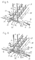
- Fig. 5 is a magnified perspective view of essential parts showing a fourth state at the end of sewing by the same sewing machine.
- Fig. 6 is a magnified perspective view of essential parts showing a fifth state at the end of sewing by the same sewing machine.
- Fig. 7 is a magnified perspective view of essential parts showing a sixth state at the end of sewing by the same sewing machine.
- Fig. 8 is a magnified perspective view of essential parts showing a seventh state at the end of sewing by the same sewing machine.
- FIG. 1 shows the bed portion of a cylinder bed type double chain stitch sewing machine according to the invention.
- a cylinder bed 1 of this sewing machine comprises a feed dog 2 for feeding the cloth in the direction of arrow F by moving vertically and longitudinally, a looper 3 making elliptical motions laterally and longitudinally, and a throat plate (not shown) fixed through a screw hole 4, and above this cylinder bed 1 is disposed a needle bar 7 fitting needles 5, 6 parallel laterally.
- a first cutter 11 is disposed at the left side of the needle drop point, that is, the position of vertical motion of the two needles 5, 6 in the sewing machine bed.
- This first cutter 11 is composed of a first receiving knife 13 extended nearly to the needle drop point along the lower side of the throat plate, being fixed to the rear part of the cylinder bed 1 through a screw 12, a first hook knife 16 fitted rotatably almost to the front side of the cylinder bed 1 through a step screw 14, having a hook 15 formed at the leading end as looper thread engaging means, and a pressing spring 17 for pressing the hook 15 to the lower side of the receiving knife 13 when cutting.
- a slot 18 is formed at the rear end of the first hook knife 16 of the first cutter 11.
- an air cylinder 19 is provided as the forward and backward drive mechanism, and an operation piece 21 is fixed to a piston rod 20 of the air cylinder 19 so as to be adjustable in position through a screw 22.
- a pin 23 provided in the operation piece 21 is fitted into the slot 18 formed in the first hook knife 16, and by the air pressure supplied into the air cylinder 19 through a pipe 24 from a high pressure air source such as compressor not shown in the drawing, the piston rod 20 is driven back and forth in the direction of arrow A, so that the first hook knife 16 is pivoted in the direction of arrow B about the step screw 14 through the operation piece 21.
- a second cutter 25 is provided at the right side of the needle drop point in the cylinder bed 1.
- This second cutter 25 is composed of a second hook knife 28 forming hooks 26, 27 at two positions in the leading end, and moving reciprocally laterally along the upper side of the blade portion 3b of the looper 3, and a second receiving knife 30 provided at the backward position of the hook knife 28, being pressed against the second hook knife 28 by a pressing spring 29.
- the second hook knife 28 of the second cutter 25 is also driven back and forth in the direction of arrow E by forward and backward moving mechanism such as air cylinder and solenoid not shown in the drawing.
- the cloth W set on the throat plate is fed in the direction of arrow F by the feed dog 2, and a double chain stitch S of seam symbol 406 is formed in the cloth W by needle threads 8, 9 and looper thread 10 passed respectively through the right and left needles 5, 6 and looper 3.
- the air cylinder 19 is actuated to turn the first hook knife 16 in the clockwise direction, and the hook 15 at the leading end of the first hook knife 16 moves across the front side above the blade portion 3b of the looper 3 between the eyelet 3e of the looper 3 and the left needle 5 from behind the looper 3, and hooks to be engaged with the looper thread 10 consecutive to the eyelet 3e of the looper 3 from the cloth W as shown in Fig. 3.
- the right and left needles 5, 6 fall into a triangular space of threads formed by the looper thread 10, blade portion 3b of the looper 3, and needle threads 8, 9, and the looper 3 moves back rightward through the front side of the needles 5, 6, and, as shown in Fig. 4, the looper thread 10 is engaged at a forward position of the needle 5 by the hook 15, and a slightly long loop 10L is formed.
- the looper 3 picks up new needle thread loops 8L, 9L formed by the needles 5, 6 moving up through the bottom dead center while advancing leftward at the rear side of the needles 5, 6 through the right dead center, showing the state of advancing almost one stitch from the state in Fig. 2.
- the longer loop 10L of the looper thread 10 engaged with the hook 15 is kept in engaged state slightly above the looper 3.
- the second hook knife 28 in the second cutter 25 is reciprocally moved laterally, and, as shown in Fig. 6, the looper thread 10 consecutive from the cloth W to the looper 3 is hooked by the hook 26 at its leading end, and the two needle threads 8, 9 extending downward of the blade portion 3b of the looper 3 are hooked by the hook 27, and then in collaboration with the receiving knife 30, these threads 10, 8, 9 are cut off at the right side of the seam S.
- the cut thread end at the side consecutive to the looper 3 of the looper thread 10 engaged with the hook 26 is elastically pinched and held between the second hook knife 28 and pressing spring 29.
- the air cylinder 19 is actuated, and the first hook knife 16 at the first cutter 11 is turned counterclockwise as shown in Fig. 8 until the hook 15 is returned to the position of the receiving knife 13, then the engagement portion of the looper thread 10 engaged with the hook 15 is cut off.
- the other cut loop thread end 10f remaining consecutively to the swing end of the cloth W is short, and the other separated cut-off loop thread end 10e is at the pressing spring 17 side of the hook 15, and is pinched and held between the first hook knife 16 and pressing spring 17.
- both thread ends 10e, 10f thus being cut off are not continuous, and when the cloth W is removed from the sewing machine, the thread end 10e pinched and held between the first hook knife 16 and pressing spring 17 is pulled out of the loops 8LL, 9LL of needle threads at the end of sewing, while the thread end 10f remaining consecutively to the cloth W side is not pulled out, so that raveling does not occur.
- the thread end 10e being cut off and pinched and held between the first hook knife 16 and pressing spring 17 is released when the hook knife 16 turns the next time, and it may be removed, at this time, by a waste thread suction device or the like.
- the second cutter 25 in thread cutting action, is operated earlier than the first cutter 11, but they may be operated simultaneously or in reverse order.
- Driving of the sewing machine for one stitch and control of driving of the cutters 11, 15 are not specifically described, but it is possible to employ various control means used in existing sewing machines such as rotation control device of motor and control depending on the detection signal from rotation detector mounted on sewing machine main shaft.
- the air cylinder is used in the embodiment, but solenoid, hydraulic cylinder or others may be also employed.
Landscapes
- Engineering & Computer Science (AREA)
- Textile Engineering (AREA)
- Sewing Machines And Sewing (AREA)
Applications Claiming Priority (3)
| Application Number | Priority Date | Filing Date | Title |
|---|---|---|---|
| JP67374/96 | 1996-02-28 | ||
| JP6737496 | 1996-02-28 | ||
| JP06737496A JP3318482B2 (ja) | 1996-02-28 | 1996-02-28 | 縫い目ほつれ防止方法及び装置 |
Publications (3)
| Publication Number | Publication Date |
|---|---|
| EP0792962A2 true EP0792962A2 (fr) | 1997-09-03 |
| EP0792962A3 EP0792962A3 (fr) | 1998-03-11 |
| EP0792962B1 EP0792962B1 (fr) | 2002-06-19 |
Family
ID=13343183
Family Applications (1)
| Application Number | Title | Priority Date | Filing Date |
|---|---|---|---|
| EP97103263A Expired - Lifetime EP0792962B1 (fr) | 1996-02-28 | 1997-02-27 | Procédé et dispositif pour éviter qu'une couture ne se défasse dans une machine à coudre à point de chaínette double |
Country Status (7)
| Country | Link |
|---|---|
| US (1) | US5722338A (fr) |
| EP (1) | EP0792962B1 (fr) |
| JP (1) | JP3318482B2 (fr) |
| KR (1) | KR100453732B1 (fr) |
| CN (1) | CN1081251C (fr) |
| DE (1) | DE69713416T2 (fr) |
| TW (1) | TW313602B (fr) |
Cited By (4)
| Publication number | Priority date | Publication date | Assignee | Title |
|---|---|---|---|---|
| EP0897030A3 (fr) * | 1997-08-12 | 1999-09-22 | Pegasus Sewing Machine Mfg. Co., Ltd. | Procédé et dispositif pour éviter qu'une couture se défait dans une machine à coudre à point de chaínette double |
| CN100347371C (zh) * | 2001-06-01 | 2007-11-07 | G.M.普法夫有限公司 | 用于形成单线链式缝合的端部结头的方法和装置 |
| DE10055218B4 (de) * | 1999-11-09 | 2013-07-04 | Yamato Mishin Seizo K.K. | Vorrichtung und Nähmaschine zum Verhindern des Auftrennens von Nähten |
| RU2563755C1 (ru) * | 2011-08-08 | 2015-09-20 | Ямато Соуинг Машин МГФ. Ко. Лтд. | Швейная машина с многониточным цепным стежком и устройством предотвращения распускания шва |
Families Citing this family (13)
| Publication number | Priority date | Publication date | Assignee | Title |
|---|---|---|---|---|
| JP3571576B2 (ja) * | 1999-05-06 | 2004-09-29 | ペガサスミシン製造株式会社 | 縫目ほつれ防止装置 |
| US6332419B1 (en) * | 2001-03-20 | 2001-12-25 | Fei-Lung Ku | Auxillary device of a sewing machine |
| JP4501136B2 (ja) * | 2005-04-14 | 2010-07-14 | ヤマトミシン製造株式会社 | 縫い目のほつれ防止装置 |
| JP2007075362A (ja) * | 2005-09-14 | 2007-03-29 | Yamato Sewing Mach Co Ltd | 縫目構造 |
| JP2009061102A (ja) * | 2007-09-06 | 2009-03-26 | Juki Corp | ミシンの糸切り装置 |
| JP2009195464A (ja) * | 2008-02-21 | 2009-09-03 | Juki Corp | ミシンの糸切り装置 |
| JP5468334B2 (ja) * | 2009-08-31 | 2014-04-09 | ペガサスミシン製造株式会社 | 縫目ほつれ防止方法およびその装置 |
| JP5618241B2 (ja) * | 2010-03-11 | 2014-11-05 | ヤマトミシン製造株式会社 | 縫目のほつれ止め方法及び縫目のほつれ止め装置 |
| JP5885018B2 (ja) * | 2011-09-13 | 2016-03-15 | ヤマトミシン製造株式会社 | 二重環縫いの縫目のほつれ止め方法及び二重環縫いミシンの縫目のほつれ止め装置 |
| JP5610405B2 (ja) * | 2012-04-03 | 2014-10-22 | ヤマトミシン製造株式会社 | 生地の縫製方法及び二重環縫いミシン |
| JP6395137B2 (ja) * | 2015-05-11 | 2018-09-26 | ヤマトミシン製造株式会社 | 縫目のほつれ止め装置付き二重環縫いミシン |
| US10260184B2 (en) * | 2017-05-11 | 2019-04-16 | L&P Property Management Company | Quilting machine |
| JP7324393B2 (ja) * | 2019-08-10 | 2023-08-10 | ヤマトミシン製造株式会社 | 縫目のほつれ止め方法及び縫目のほつれ止め装置 |
Family Cites Families (11)
| Publication number | Priority date | Publication date | Assignee | Title |
|---|---|---|---|---|
| DE1485429C3 (de) * | 1965-05-08 | 1973-09-20 | Union Special Maschinenfabrik Gmbh, 7000 Stuttgart | Abschneidemnchtung fur Doppel kettenstich Nahmaschinen |
| US3386402A (en) * | 1966-07-05 | 1968-06-04 | Singer Co | Thread trimming mechanism for sewing machines |
| US3871307A (en) * | 1973-04-05 | 1975-03-18 | Munsingwear Inc | Placket forming machine |
| US3894502A (en) * | 1973-04-12 | 1975-07-15 | Pfaff Ind Masch | Thread cutting arrangement on lock stitch sewing machines |
| US3867892A (en) * | 1974-05-09 | 1975-02-25 | Singer Co | Underbed thread trimmer for chainstitch sewing machines |
| JPS52152356A (en) * | 1976-06-10 | 1977-12-17 | Tokyo Juki Industrial Co Ltd | Yarn cutter for chain stitch sewing machine |
| JPS62298393A (ja) * | 1986-06-19 | 1987-12-25 | ペガサスミシン製造株式会社 | シリンダ−ミシンの糸切断装置 |
| JPH04354979A (ja) * | 1991-06-03 | 1992-12-09 | Morimoto Mfg Co Ltd | 複数針ミシンの飾り糸切断装置 |
| US5417173A (en) * | 1991-10-24 | 1995-05-23 | Yamato Mishin Seizo Kabushiki Kaisha | Method of cutting threads in a sewing machine and device for performing the same |
| JP2879399B2 (ja) * | 1993-02-09 | 1999-04-05 | ヤマトミシン製造株式会社 | 縫い目のほつれ防止方法及び装置 |
| US5417137A (en) * | 1994-08-29 | 1995-05-23 | Krasny; G. Mitchell | Metronome apparatus |
-
1996
- 1996-02-28 JP JP06737496A patent/JP3318482B2/ja not_active Expired - Fee Related
-
1997
- 1997-02-13 TW TW086101612A patent/TW313602B/zh not_active IP Right Cessation
- 1997-02-19 US US08/801,358 patent/US5722338A/en not_active Expired - Fee Related
- 1997-02-19 KR KR1019970004950A patent/KR100453732B1/ko not_active Expired - Fee Related
- 1997-02-27 EP EP97103263A patent/EP0792962B1/fr not_active Expired - Lifetime
- 1997-02-27 DE DE69713416T patent/DE69713416T2/de not_active Expired - Fee Related
- 1997-02-27 CN CN97102584A patent/CN1081251C/zh not_active Expired - Lifetime
Cited By (4)
| Publication number | Priority date | Publication date | Assignee | Title |
|---|---|---|---|---|
| EP0897030A3 (fr) * | 1997-08-12 | 1999-09-22 | Pegasus Sewing Machine Mfg. Co., Ltd. | Procédé et dispositif pour éviter qu'une couture se défait dans une machine à coudre à point de chaínette double |
| DE10055218B4 (de) * | 1999-11-09 | 2013-07-04 | Yamato Mishin Seizo K.K. | Vorrichtung und Nähmaschine zum Verhindern des Auftrennens von Nähten |
| CN100347371C (zh) * | 2001-06-01 | 2007-11-07 | G.M.普法夫有限公司 | 用于形成单线链式缝合的端部结头的方法和装置 |
| RU2563755C1 (ru) * | 2011-08-08 | 2015-09-20 | Ямато Соуинг Машин МГФ. Ко. Лтд. | Швейная машина с многониточным цепным стежком и устройством предотвращения распускания шва |
Also Published As
| Publication number | Publication date |
|---|---|
| KR100453732B1 (ko) | 2005-04-25 |
| DE69713416T2 (de) | 2003-01-16 |
| KR970062124A (ko) | 1997-09-12 |
| JP3318482B2 (ja) | 2002-08-26 |
| DE69713416D1 (de) | 2002-07-25 |
| EP0792962B1 (fr) | 2002-06-19 |
| EP0792962A3 (fr) | 1998-03-11 |
| TW313602B (en) | 1997-08-21 |
| US5722338A (en) | 1998-03-03 |
| CN1081251C (zh) | 2002-03-20 |
| JPH09225163A (ja) | 1997-09-02 |
| CN1161390A (zh) | 1997-10-08 |
Similar Documents
| Publication | Publication Date | Title |
|---|---|---|
| US5722338A (en) | Method and apparatus for preventing seam from raveling in double chain stitch sewing machine | |
| EP2716804B1 (fr) | Procédé pour empêcher une couture de se défaire, dispositif pour empêcher une couture de se défaire, et structure de couture | |
| KR20080045071A (ko) | 재봉기 | |
| US5125351A (en) | Thread trimmer system for in-line chain stitch cylinder bed sewing machine | |
| US7497177B2 (en) | Seam ravel preventing apparatus and ravel preventing method | |
| EP0897030B1 (fr) | Procédé et dispositif pour éviter qu'une couture se défait dans une machine à coudre à point de chaínette double | |
| US5333565A (en) | Thread cutting via reciprocating arm with pockets and a trimming plate | |
| JP3499407B2 (ja) | 縫い目ほつれ防止方法及び装置 | |
| JP3535353B2 (ja) | 縫い目ほつれ防止方法及び装置 | |
| JP2009066191A (ja) | 縫目ほつれ防止方法およびその装置 | |
| EP1050614B1 (fr) | Dispositif pour éviter qu'un point de couture ne se défasse | |
| US4029029A (en) | Method and apparatus for tufting high and low cut pile in the same row | |
| JP2009240389A (ja) | ミシン | |
| JP6059917B2 (ja) | 二重環縫いミシン | |
| JP3527835B2 (ja) | 二重環縫いミシンの縫目ほつれ防止方法及びその装置 | |
| JP2003236281A (ja) | ミシン | |
| JP7379781B2 (ja) | 縫目のほつれ止め方法及び縫目のほつれ止め装置 | |
| TWI861175B (zh) | 接縫之綻線防止方法及接縫之綻線防止裝置 | |
| JPH0794253B2 (ja) | 環糸形成機構における糸捕捉成否判別装置 | |
| JPH01250294A (ja) | 縁かがり縫いミシンに用いる空環縫い込み装置 | |
| JPH0736636Y2 (ja) | 多列二重環縫いミシンの糸切り装置 | |
| JP2003245486A (ja) | 二重環縫いミシン | |
| JPS63214277A (ja) | ミシンの糸切り装置 | |
| JPS5913238B2 (ja) | ミシンの糸切り方法 | |
| JPS63145696A (ja) | 多列二重環縫いミシンの糸切り装置 |
Legal Events
| Date | Code | Title | Description |
|---|---|---|---|
| PUAI | Public reference made under article 153(3) epc to a published international application that has entered the european phase |
Free format text: ORIGINAL CODE: 0009012 |
|
| AK | Designated contracting states |
Kind code of ref document: A2 Designated state(s): DE FR GB IT |
|
| PUAL | Search report despatched |
Free format text: ORIGINAL CODE: 0009013 |
|
| AK | Designated contracting states |
Kind code of ref document: A3 Designated state(s): DE FR GB IT |
|
| 17P | Request for examination filed |
Effective date: 19980821 |
|
| 17Q | First examination report despatched |
Effective date: 20000928 |
|
| GRAG | Despatch of communication of intention to grant |
Free format text: ORIGINAL CODE: EPIDOS AGRA |
|
| GRAG | Despatch of communication of intention to grant |
Free format text: ORIGINAL CODE: EPIDOS AGRA |
|
| GRAH | Despatch of communication of intention to grant a patent |
Free format text: ORIGINAL CODE: EPIDOS IGRA |
|
| GRAH | Despatch of communication of intention to grant a patent |
Free format text: ORIGINAL CODE: EPIDOS IGRA |
|
| GRAA | (expected) grant |
Free format text: ORIGINAL CODE: 0009210 |
|
| AK | Designated contracting states |
Kind code of ref document: B1 Designated state(s): DE FR GB IT |
|
| REG | Reference to a national code |
Ref country code: GB Ref legal event code: FG4D |
|
| REF | Corresponds to: |
Ref document number: 69713416 Country of ref document: DE Date of ref document: 20020725 |
|
| ET | Fr: translation filed | ||
| PLBE | No opposition filed within time limit |
Free format text: ORIGINAL CODE: 0009261 |
|
| STAA | Information on the status of an ep patent application or granted ep patent |
Free format text: STATUS: NO OPPOSITION FILED WITHIN TIME LIMIT |
|
| 26N | No opposition filed |
Effective date: 20030320 |
|
| PGFP | Annual fee paid to national office [announced via postgrant information from national office to epo] |
Ref country code: IT Payment date: 20080223 Year of fee payment: 12 Ref country code: GB Payment date: 20080220 Year of fee payment: 12 Ref country code: DE Payment date: 20080219 Year of fee payment: 12 |
|
| PGFP | Annual fee paid to national office [announced via postgrant information from national office to epo] |
Ref country code: FR Payment date: 20080214 Year of fee payment: 12 |
|
| GBPC | Gb: european patent ceased through non-payment of renewal fee |
Effective date: 20090227 |
|
| REG | Reference to a national code |
Ref country code: FR Ref legal event code: ST Effective date: 20091030 |
|
| PG25 | Lapsed in a contracting state [announced via postgrant information from national office to epo] |
Ref country code: DE Free format text: LAPSE BECAUSE OF NON-PAYMENT OF DUE FEES Effective date: 20090901 |
|
| PG25 | Lapsed in a contracting state [announced via postgrant information from national office to epo] |
Ref country code: GB Free format text: LAPSE BECAUSE OF NON-PAYMENT OF DUE FEES Effective date: 20090227 Ref country code: FR Free format text: LAPSE BECAUSE OF NON-PAYMENT OF DUE FEES Effective date: 20090302 |
|
| PG25 | Lapsed in a contracting state [announced via postgrant information from national office to epo] |
Ref country code: IT Free format text: LAPSE BECAUSE OF NON-PAYMENT OF DUE FEES Effective date: 20090227 |