EP0792983A2 - Dispositif d'autoblocage pour une serrure actionnée par une rotation de 360 - Google Patents
Dispositif d'autoblocage pour une serrure actionnée par une rotation de 360 Download PDFInfo
- Publication number
- EP0792983A2 EP0792983A2 EP97102129A EP97102129A EP0792983A2 EP 0792983 A2 EP0792983 A2 EP 0792983A2 EP 97102129 A EP97102129 A EP 97102129A EP 97102129 A EP97102129 A EP 97102129A EP 0792983 A2 EP0792983 A2 EP 0792983A2
- Authority
- EP
- European Patent Office
- Prior art keywords
- bolt
- driver
- lock
- locking
- pin
- Prior art date
- Legal status (The legal status is an assumption and is not a legal conclusion. Google has not performed a legal analysis and makes no representation as to the accuracy of the status listed.)
- Withdrawn
Links
Images

Classifications
-
- E—FIXED CONSTRUCTIONS
- E05—LOCKS; KEYS; WINDOW OR DOOR FITTINGS; SAFES
- E05B—LOCKS; ACCESSORIES THEREFOR; HANDCUFFS
- E05B55/00—Locks in which a sliding latch is used also as a locking bolt
-
- E—FIXED CONSTRUCTIONS
- E05—LOCKS; KEYS; WINDOW OR DOOR FITTINGS; SAFES
- E05B—LOCKS; ACCESSORIES THEREFOR; HANDCUFFS
- E05B17/00—Accessories in connection with locks
- E05B17/20—Means independent of the locking mechanism for preventing unauthorised opening, e.g. for securing the bolt in the fastening position
- E05B17/2007—Securing, deadlocking or "dogging" the bolt in the fastening position
- E05B17/2049—Securing, deadlocking or "dogging" the bolt in the fastening position following the movement of the bolt
- E05B17/2053—Securing, deadlocking or "dogging" the bolt in the fastening position following the movement of the bolt moving pivotally or rotatively relating to the bolt
Definitions
- the invention relates to a door lock which can be actuated from the inside and / or outside of a door by a handle and which is equipped with a latch and a bolt, wherein when the door is locked, an automatic bolt locking is carried out at the same time by a key.
- a lock which contains a blocking device can be found in DE 28 04 603 C2. With this lock, the guard locking also takes over the locking of the bolt. At the same time as the key is actuated, the blocking device is also activated each time. A second key is not available for this, as is usually required in the prior art.
- the automatic dependency between the turning of the key and the activation of the blocking device activates a blocking unit consisting of small components.
- the insertion forces that may occur against the head of the bolt or the latch bolt are positively derived on the lock housing. As a result of this measure, the lock cannot be opened by force by the gate pin being sheared off by pushing in the bolt or the latch bolt.
- the object of the invention is to provide a simple but effective automatic bolt lock for a single-turn lock.
- the invention is solved according to the characterizing part of patent claim 1.
- a driver By using a driver, it is possible to lock the bolt in the locked position against violent pushing back when the bolt is excluded.
- the entire prefabricated mechanism is located on a locking plate, both for locking out the locking bar and simultaneously for locking the locking bar.
- Within the guide tail is guided in a horizontal plane by means of a pin preferably used.
- the bolt finds another guide in an opening in the faceplate.
- the bolt which is mounted at two points in this way, is able to carry out a clean, sliding horizontal movement of the bolt.
- There is a carrier pocket on the bolt tail which is necessary to carry out the horizontal movement due to the rotational movement of a carrier with a carrier pin located thereon.
- the aforementioned driver slides due to a molded projection within a guideway that is designed in the shape of a circular arc.
- the end of the guideway also causes the end of the bolt exclusion or the position that the bolt assumes when it is included.
- the driver pin is also formed, which interacts with the driver pocket of the bolt tail in such a way that the movement on the circular arc-shaped path can cause the bolt closure.
- the arcuate path is designed so that it allows a certain distance from both sides of the lock cylinder. This ensures, on the one hand, that the driver remains securely in an enclosed position and, on the other hand, also securely remains in the open position of the bolt when the bolt is excluded.
- the driver is still loaded by a spring, one end of which is fastened to the locking plate and the other end of which has a rounding which engages in a first or second catch within the driver.
- the first catch represents the position of the blocked bolt
- the second catch represents the position when the bolt is retracted.
- the driver pin on the driver transports the bolt into the closed position as a result of engaging in the carrier pocket.
- the bolt stops at the angle at which the driver pin leaves the driver pocket.
- this is also the position in which the bolt is automatically blocked. This is accomplished in that the driver pin is now outside the Driver pocket is located and a stop surface, which is located after the driver pocket on the bolt tail, is automatically pressed against the driver pin when the bolt is pressed. Because the driver is located outside the center of the locking cylinder, it lies within a dead point and cannot be pushed out of this position by the force to be applied. At the same time, however, becomes quasi Jamming "or a Blocking "of the bolt brought about, so that the occurring forces, which bear on the bolt, are forwarded into the fastening of the bolt plate and thus simultaneously absorbed by the lock case.
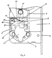
- a guide pin 13 which is fastened to the locking tail 10, can be displaced in the closing direction of the locking bolt 1 within an elongated recess 11.
- a change 5 is also attached, which is used to carry out the latch actuation.
- the locking plate 6 has an opening 21 through which the cylinder or key used accordingly passes through the lock cover or lock case 4.
- On the locking plate 6 is a guide rib 7 molded. This guide rib 7 runs on a circular arc in order to enable the guide engaging with a projection 8 in the guide rib 7 to run on the circular arc path.
- the guide rib 7 is designed so that it extends from the center of the opening 21 and thus from the center of the lock cylinder, on both sides.
- the projection 8 is non-positively and positively connected to a driver 2, which in turn serves to exclude and include the bolt 1 via the bolt tail 10 due to the rotation of the key.
- a driver 2 which in turn serves to exclude and include the bolt 1 via the bolt tail 10 due to the rotation of the key.
- a driver pin 9 on the driver 2, which is also integrally and positively molded.
- This driver pin 9, as FIG. 1 clearly shows, engages in a driver pocket 12 which is located within the bolt tail 10. If the driver 2 is now pivoted on the guide rib 7, the bolt 1 is also moved at the same time.
- the excluded bar is shown in FIG. It can also be seen that the driver 2 has been pivoted by the bolt exclusion. In the position where the bolt 1 is completely excluded, the driver pin 9 has left the driver pocket 12. Another bolt drive is no longer possible. If the latch 1 were now pushed back again, i.e. in its retracted position, a stop surface 14 comes into contact with the driving pin 9 located outside the driving pocket 12. This causes the bolt 1 to be blocked. The forces which occur are thus transmitted to the fixing points or fastening points of the bolt plate 6 of the lock case 4.
- the driver can remain securely in this position and is not brought out by manipulation, it is held securely in this position by a spring 16, one end of which engages in a first catch 18.
- the other end of the spring 16 is fixed by a spring holder 17.
- the driver pin 9 automatically engages in the driver pocket 12 and thus transports the bolt 1 back into the closed position via the bolt tail 10. Also in this position there is a secure mounting of the driver 2 in such a way that a second catch 19 is present, in which the spring which previously entered the first catch 18 now holds the catch 2 in the second catch 19.
- the end of the spring 16 runs from the first detent 18 to the second detent 19 via an outer edge 20 of the driver 2.
- the outer edge 20 is slightly convex in order to ensure reliable closing.
- Both the locking plate 6 and the driver 2 and the locking tail 10 can be made from precision castings.
- the corresponding material quality results from the strength that such a lock described above should have.
- the concept according to the invention can also be applied to two-turn locks, in which case it would be necessary if a further driving pin were provided on the driver 2 at a corresponding point.
Landscapes
- Lock And Its Accessories (AREA)
Applications Claiming Priority (2)
| Application Number | Priority Date | Filing Date | Title |
|---|---|---|---|
| DE19607504 | 1996-02-29 | ||
| DE1996107504 DE19607504A1 (de) | 1996-02-29 | 1996-02-29 | Automatische Riegelblockierung eines eintourigen Schlosses |
Publications (2)
| Publication Number | Publication Date |
|---|---|
| EP0792983A2 true EP0792983A2 (fr) | 1997-09-03 |
| EP0792983A3 EP0792983A3 (fr) | 1997-09-10 |
Family
ID=7786671
Family Applications (1)
| Application Number | Title | Priority Date | Filing Date |
|---|---|---|---|
| EP97102129A Withdrawn EP0792983A3 (fr) | 1996-02-29 | 1997-02-11 | Dispositif d'autoblocage pour une serrure actionnée par une rotation de 360 |
Country Status (2)
| Country | Link |
|---|---|
| EP (1) | EP0792983A3 (fr) |
| DE (1) | DE19607504A1 (fr) |
Cited By (1)
| Publication number | Priority date | Publication date | Assignee | Title |
|---|---|---|---|---|
| RU2425203C2 (ru) * | 2006-02-17 | 2011-07-27 | Моттура Серратуре Ди Сикуредза С.П.А. | Замок с предохранителем |
Family Cites Families (8)
| Publication number | Priority date | Publication date | Assignee | Title |
|---|---|---|---|---|
| US3464242A (en) * | 1967-05-08 | 1969-09-02 | Sakuzo Torii | Dead bolt lock operating means |
| FR2222875A5 (en) * | 1973-03-23 | 1974-10-18 | Ponsy Jacques | Door lock formed of plastic components - has bolt spring loaded by folded extension band of handle connection collar |
| DE2317835A1 (de) * | 1973-04-10 | 1974-10-17 | Artur Lupp | Aufliegendes moebelschloss aus kunststoff |
| DE2804603C2 (de) * | 1978-02-03 | 1982-01-14 | Fa. Wilhelm Dörrenhaus, 5620 Velbert | Riegelblockiervorrichtung in einem Schloß mit schlüsselbetätigbarer Zuhaltung |
| NL174973C (nl) * | 1978-06-30 | 1984-09-03 | Lips Slotenfab | Deurslot met grote slag. |
| FI830826L (fi) * | 1983-03-11 | 1984-09-12 | Waertsilae Oy Ab | Doerrlaos. |
| GB9407061D0 (en) * | 1994-04-09 | 1994-06-01 | Chubb Locks Ltd | Locks |
| DE4421036C1 (de) * | 1994-06-16 | 1995-12-07 | Huwil Werke Gmbh | Schloß zur Verwendung als Links- oder Rechtsschloß |
-
1996
- 1996-02-29 DE DE1996107504 patent/DE19607504A1/de not_active Withdrawn
-
1997
- 1997-02-11 EP EP97102129A patent/EP0792983A3/fr not_active Withdrawn
Cited By (1)
| Publication number | Priority date | Publication date | Assignee | Title |
|---|---|---|---|---|
| RU2425203C2 (ru) * | 2006-02-17 | 2011-07-27 | Моттура Серратуре Ди Сикуредза С.П.А. | Замок с предохранителем |
Also Published As
| Publication number | Publication date |
|---|---|
| DE19607504A1 (de) | 1997-10-16 |
| EP0792983A3 (fr) | 1997-09-10 |
Similar Documents
| Publication | Publication Date | Title |
|---|---|---|
| DE4329997B4 (de) | Einrichtung zum Ent- und Verriegeln von zumindest zwei mit Abstand zueinander angeordneten, schwenkbaren Hauben eines Kraftfahrzeuges | |
| DE2814060A1 (de) | Einbruchsichere schliessvorrichtung | |
| DE19838623C1 (de) | Türschloß für eine Ganzglastür mit feststehendem Glasseitenteil | |
| DE69506222T2 (de) | Treibstangenverschluss für ein fenster oder eine tuer | |
| EP0408784B1 (fr) | Dispositif de blocage d'une ferrure tournant tombant pour battant | |
| EP2796645A2 (fr) | Serrure à pêne dormant d'un meuble | |
| DE3243029C2 (de) | Versenkbarer Verschluß für Schaltschranktüren | |
| DE2635977A1 (de) | Tuerschliessvorrichtung | |
| EP2735675B1 (fr) | Dispositif de fermeture pour portes doté d'une plaque de porte asymétrique | |
| DE29509503U1 (de) | Mehrfachverriegelungsanlage | |
| DE3512856C2 (de) | Gepanzerte Tür | |
| EP0792980A1 (fr) | Serrure | |
| EP0792983A2 (fr) | Dispositif d'autoblocage pour une serrure actionnée par une rotation de 360 | |
| DE29824200U1 (de) | Schutzvorrichtung | |
| DE9417227U1 (de) | Verriegelungsschloß | |
| DE20122859U1 (de) | Einsteckschloss mit Kunststoffriegel | |
| DE29610073U1 (de) | Automatische Riegelblockierung eines eintourigen Schlosses | |
| DE19541942C1 (de) | Rechts und links verwendbares Türschloß | |
| CH671603A5 (fr) | ||
| DE2345497C2 (de) | Türverschluß mit Fallen- und Sicherheitsriegel | |
| DE29610086U1 (de) | Schloß | |
| DE20211508U1 (de) | Doppelzylinder-Schwenkhebelverschluß | |
| DE3240014A1 (de) | Griffanordnung fuer tueren oder dergleichen | |
| DE29520637U1 (de) | Sicherheitsschloß für Wertbehälter | |
| DE60012064T2 (de) | Treibstangenverschlüsse |
Legal Events
| Date | Code | Title | Description |
|---|---|---|---|
| PUAI | Public reference made under article 153(3) epc to a published international application that has entered the european phase |
Free format text: ORIGINAL CODE: 0009012 |
|
| PUAL | Search report despatched |
Free format text: ORIGINAL CODE: 0009013 |
|
| STAA | Information on the status of an ep patent application or granted ep patent |
Free format text: STATUS: THE APPLICATION HAS BEEN WITHDRAWN |
|
| AK | Designated contracting states |
Kind code of ref document: A2 Designated state(s): AT BE CH DE FI FR GB IT LI LU NL SE |
|
| AK | Designated contracting states |
Kind code of ref document: A3 Designated state(s): AT BE CH DE FI FR GB IT LI LU NL SE |
|
| 18W | Application withdrawn |
Withdrawal date: 19970801 |