EP0793025A1 - Metalldübel zur Verankerung in dünnen Wandplatten - Google Patents
Metalldübel zur Verankerung in dünnen Wandplatten Download PDFInfo
- Publication number
- EP0793025A1 EP0793025A1 EP97102549A EP97102549A EP0793025A1 EP 0793025 A1 EP0793025 A1 EP 0793025A1 EP 97102549 A EP97102549 A EP 97102549A EP 97102549 A EP97102549 A EP 97102549A EP 0793025 A1 EP0793025 A1 EP 0793025A1
- Authority
- EP
- European Patent Office
- Prior art keywords
- webs
- section
- screw
- metal
- bending
- Prior art date
- Legal status (The legal status is an assumption and is not a legal conclusion. Google has not performed a legal analysis and makes no representation as to the accuracy of the status listed.)
- Granted
Links
- 238000004873 anchoring Methods 0.000 title claims description 6
- 239000002184 metal Substances 0.000 claims abstract description 24
- 238000005452 bending Methods 0.000 claims abstract description 18
- 239000004566 building material Substances 0.000 claims abstract description 4
- 238000003780 insertion Methods 0.000 claims description 3
- 230000037431 insertion Effects 0.000 claims description 3
- 230000014759 maintenance of location Effects 0.000 abstract 3
- 239000002023 wood Substances 0.000 abstract 1
- 238000004519 manufacturing process Methods 0.000 description 3
- 241001494479 Pecora Species 0.000 description 2
- 239000000463 material Substances 0.000 description 2
- 229910000639 Spring steel Inorganic materials 0.000 description 1
- 239000007769 metal material Substances 0.000 description 1
- BASFCYQUMIYNBI-UHFFFAOYSA-N platinum Chemical compound [Pt] BASFCYQUMIYNBI-UHFFFAOYSA-N 0.000 description 1
- 238000004080 punching Methods 0.000 description 1
- 230000003014 reinforcing effect Effects 0.000 description 1
- 230000000284 resting effect Effects 0.000 description 1
Images
Classifications
-
- E—FIXED CONSTRUCTIONS
- E04—BUILDING
- E04F—FINISHING WORK ON BUILDINGS, e.g. STAIRS, FLOORS
- E04F13/00—Coverings or linings, e.g. for walls or ceilings
- E04F13/07—Coverings or linings, e.g. for walls or ceilings composed of covering or lining elements; Sub-structures therefor; Fastening means therefor
- E04F13/08—Coverings or linings, e.g. for walls or ceilings composed of covering or lining elements; Sub-structures therefor; Fastening means therefor composed of a plurality of similar covering or lining elements
- E04F13/0801—Separate fastening elements
- E04F13/0832—Separate fastening elements without load-supporting elongated furring elements between wall and covering elements
- E04F13/0833—Separate fastening elements without load-supporting elongated furring elements between wall and covering elements not adjustable
- E04F13/0835—Separate fastening elements without load-supporting elongated furring elements between wall and covering elements not adjustable the fastening elements extending into the back side of the covering elements
- E04F13/0837—Separate fastening elements without load-supporting elongated furring elements between wall and covering elements not adjustable the fastening elements extending into the back side of the covering elements extending completely through the covering elements
-
- F—MECHANICAL ENGINEERING; LIGHTING; HEATING; WEAPONS; BLASTING
- F16—ENGINEERING ELEMENTS AND UNITS; GENERAL MEASURES FOR PRODUCING AND MAINTAINING EFFECTIVE FUNCTIONING OF MACHINES OR INSTALLATIONS; THERMAL INSULATION IN GENERAL
- F16B—DEVICES FOR FASTENING OR SECURING CONSTRUCTIONAL ELEMENTS OR MACHINE PARTS TOGETHER, e.g. NAILS, BOLTS, CIRCLIPS, CLAMPS, CLIPS OR WEDGES; JOINTS OR JOINTING
- F16B13/00—Dowels or other devices fastened in walls or the like by inserting them in holes made therein for that purpose
- F16B13/12—Separate metal or non-separate or non-metal dowel sleeves fastened by inserting the screw, nail or the like
- F16B13/122—Separate metal or non-separate or non-metal dowel sleeves fastened by inserting the screw, nail or the like made from a sheet-metal blank
Definitions
- the invention relates to a metal dowel for anchoring in thin wall panels made of plasterboard, pressboard or the like.
- the dowel shaft being worked out from a sheet metal plate and provided with retaining webs which are stamped out of the shaft and are alternately semicircular in shape on both sides, the width and pitch of the thread form the screw to be screwed in are adapted such that the retaining webs engage in their thread grooves.
- Such a metal dowel is known from EP 0 629 786 A1 , in which two expandable shaft parts are integrally connected to one another at their tips via a tearable thin web and are folded onto one another.
- the semicircular holding bars for screwing in the screw are located in the head area of the shaft.
- This metal dowel can be easily hammered into the plasterboard and also offers enormous holding power.
- it has the disadvantage that the double shaft length of sheet metal material is consumed for the manufacture of the shaft by the two shaft halves which are folded onto one another.
- the object of the invention is to design this metal dowel so that less material is required with the same functionality and the same good holding force.
- the entire shaft is formed from three sections, of which the first section lying on the insertion side carries the holding webs, the second section lying in the middle is formed by two axially parallel outer bending webs and two inner bending webs , which are separated from one another by slots and can be folded away in the opposite direction, and the third section located at the head end is provided with alternately semicircularly shaped guide shells for inserting the screw.
- the dowel shaped in this way can be easily driven into said wall panels.
- the outer webs of the middle section bend to one side and the two inner webs to the other side and are supported on the back of the panel with half the width of the bending webs.
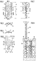
- the metal dowel shown in the figures is used for anchoring in thin wall panels made of plasterboard, pressboard or the like. Building material. His sheep 1 is, as shown in Fig. 5 , punched out in one layer from a sheet metal plate and shaped and consists of three sections. The first portion 4 has at its insertion end two tips 3 and is provided with a plurality of the central strip punched out semicircular retaining webs 2 which are alternately formed out on both sides and are adapted in width and pitch of the thread form of the screw to be screwed 13 such that the retaining webs 2 engage in their thread grooves 19 .
- the middle section 5 serves for the actual anchoring and is formed by two axially parallel outer bending webs 7 and two inner bending webs 8 , which are separated from one another by slots 12 from the two outer bending webs 7 .
- the two outer webs 7 are bent slightly to one side at the fold lines K1 , K2 and K3 from the shaft plane, while the two inner webs 8 are bent away to the opposite side at the fold lines lying at the same height and, as can be seen from FIG. 2 , with the outer webs 7 form a narrow rhombus in cross section.
- the inner bending webs 8 are connected to one another by two transverse webs 10 which, on the side provided for the buckling, span the free space required for inserting the screw 13 in a semicircle.
- the third, head-side section 6 is provided with semicircular guide shells 9 , which are alternately molded out of the shaft plane on both sides, for inserting the screw 13 and has, at its head end, transversely projecting tabs 14 on both sides for resting on the wall plate 15 when the dowel is hammered in. Furthermore, the bending cross section of the shaft 1 is reinforced in the insertion-side section 4 on both sides of the holder webs 2 by edges 11 bent away axially parallel.
- FIG. 6 The mode of operation of the metal dowel is illustrated in FIG. 6 .
- a flat object such as a plate 15 to attach on the wall plate 16
- the metal anchor is driven through the flaps 14 with a hammer in the wall plate 16 until the tabs 14 rest on the disk surface.
- the screw 13 is then inserted through the hole 17 in the plate 15 and the guide shells 9 of the head-side section 6 until the screw tip 18 has reached the screwing area of the lower shaft section 4 and the retaining webs 2 engage in the thread grooves 19 .
- the metal dowel remains in its anchoring position and can be used again at any time to screw in the screw 13 .
Landscapes
- Engineering & Computer Science (AREA)
- General Engineering & Computer Science (AREA)
- Architecture (AREA)
- Mechanical Engineering (AREA)
- Civil Engineering (AREA)
- Structural Engineering (AREA)
- Finishing Walls (AREA)
- Joining Of Building Structures In Genera (AREA)
- Dowels (AREA)
Abstract
Description
- Die Erfindung betrifft einen Metalldübel zur Verankerung in dünnen Wandplatten aus Gipskarton, Preßspan oder dergl. Baumaterial, wobei der Dübelschaft aus einer Blechplatine herausgearbeitet und mit aus dem Schaft herausgestanzten, abwechselnd nach beiden Seiten halbrund geformten Haltestegen versehen ist, welche in Breite und Steigung der Gewindeform der einzudrehenden Schraube derart angepaßt sind, daß die Haltestege in deren Gewinderillen eingreifen.
- Aus EP 0 629 786 A1 ist ein derartiger Metalldübel bekannt, bei welchem zwei spreizbare Schaftteile an ihren Spitzen über einen abreißbaren dünnen Steg einstückig miteinander verbunden und aufeinandergeklappt sind. Die halbrund geformten Haltestege zum Eindrehen der Schraube befinden sich hierbei im Kopfbereich des Schaftes. Beim Eindrehen der Schraube in die Gewindestege schiebt sich die Schraubenspitze zwischen die beiden Schaftteile und spreizt sie derart auseinander, daß diese an der Rückseite der Wandplatte Halt finden.
- Dieser Metalldübel läßt sich zwar leicht in die Gipskartonplatten einschlagen und bietet auch eine enorme Haltekraft. Er hat jedoch den Nachteil, daß zur Herstellung des Schaftes durch die zwei aufeinandergeklappten Schafthälften die doppelte Dübellänge an Blechmaterial verbraucht wird. Aufgabe der Erfindung ist es, diesen Metalldübel so zu gestalten, daß bei gleicher Funktionstüchtigkeit und gleich guter Haltekraft weniger Material benötigt wird.
- Diese Aufgabe wird erfindungsgemäß dadurch gelöst, daß der gesamte Schaft aus drei Abschnitten gebildet ist, wovon der erste, an der Einführungsseite liegende Abschnitt die Haltestege trägt, der zweite, in der Mitte liegende Abschnitt durch zwei achsparallel verlaufende äußere Biegestege und zwei innere Biegestege gebildet ist, welche durch Schlitze voneinander getrennt und in entgegengesetzter Richtung wegknickbar sind, und der dritte, am Kopfende befindliche Abschnitt mit abwechselnd nach beiden Seiten halbrund geformten Führungsschalen zum Einführen der Schraube versehen ist. Aufgrund dieser Schaftgestaltung ist es nunmehr möglich, den Metalldübel einlagig aus einer Blechplatine herauszustanzen und zu formen, so daß die Herstellungskosten infolge des geringeren Materialverbrauchs deutlich niedriger liegen als bei dem bekannten zweilagig ausgebildeten Metalldübel.
- Bei Verwendung von entsprechend gehärtetem Federstahl läßt sich der so geformte Dübel ohne weiteres in die besagten Wandplatten eintreiben. Durch Eindrehen der Schraube in die Haltestege an der Dübelspitze wird diese von hinten an die Platte herangezogen. Dabei knicken die äußeren Stege des mittleren Abschnitts nach der einen Seite und die beiden inneren Stegen nach der anderen Seite weg und stützen sich an der Plattenrückseite mit der halben Breite der Biegestege ab.
- In den Unteransprüchen sind weitere zur Ausgestaltung der Erfindung förderliche Merkmale angegeben. So wird durch die Weiterbildung der Erfindung nach Anspruch 2 erreicht, daß die Biegestege beim Anziehen der Schraube exakt an den vorgegebenen Knicklinien wegknicken. Die Verbindung der inneren Biegestege durch halbrund geformte Querstege nach Anspruch 3 bewirkt eine Verstärkung der Biegestege und damit des mittleren Schaftabschnitts und sorgt dafür, daß der Dübel beim Eintreiben in die Wandplatte seine Form behält. Eine zusätzlich verstärkende Wirkung wird durch das Abknicken der achsparallelen Schaftkanten nach Anspruch 4 erreicht.
- In der Zeichnung ist ein Ausführungsbeispiel der Erfindung dargestellt, welches nachfolgend beschrieben wird. Es zeigt
- Fig. 1
- einen erfindungsgemäßen Metalldübel in Vorderansicht,
- Fig. 2
- den Metalldübel im Längsschnitt nach Linie II-II in Fig. 1,
- Fig. 3
- den Metalldübel in Draufsicht,
- Fig. 4
- einen Querschnitt durch den Schaff nach Linie IV - IV in Fig. 1,
- Fig. 5
- eine zur Herstellung des Dübels verwendete Platine nach dem Ausstanzen des Schaft-Rohlings und
- Fig. 6
- den Metalldübel im Einbauzustand, und zwar links vor und rechts nach dem Eindrehen der Schraube.
- Der in den Figuren dargestellte Metalldübel dient zur Verankerung in dünnen Wandplatten aus Gipskarton, Preßspan oder dgl. Baumaterial. Sein Schaff 1 ist, wie aus Fig. 5 ersichtlich, einlagig aus einer Blechplatine herausgestanzt und geformt und besteht aus drei Abschnitten. Der erste Abschnitt 4 besitzt an seinem Einführungsende zwei Spitzen 3 und ist mit mehreren aus dem mittleren Streifen herausgestanzten halbrunden Haltestegen 2 versehen, welche abwechselnd nach beiden Seiten herausgeformt sind und in Breite und Steigung der Gewindeform der einzudrehenden Schraube 13 derart angepaßt sind, daß die Haltestege 2 in deren Gewinderillen 19 eingreifen.
- Der mittlere Abschnit 5 dient der eigentlichen Verankerung und ist durch zwei, achsparallel verlaufende äußere Biegestege 7 und zwei innere Biegestege 8 gebildet, die von den beiden äußeren Biegestegen 7 durch Schlitze 12 voneinander getrennt sind. Die beiden äußeren Stege 7 sind an den Knicklinien K1, K2 und K3 aus der Schaftebene leicht nach einer Seite weggeknickt, während die beiden inneren Stege 8 an den auf gleicher Höhe liegenden Knicklinien nach der entgegengesetzten Seite weggeknickt sind und, wie aus Fig. 2 ersichtlich, mit den äußeren Stegen 7 im Querschnitt einen schmalen Rhombus bilden. Die inneren Biegestege 8 sind untereinander durch zwei Querstege 10 verbunden, welche auf der zum Ausknicken vorgesehenen Seite den zum Einführen der Schraube 13 benötigten Freiraum halbrund überspannen.
- Der dritte, kopfseitige Abschnitt 6 ist mit abwechselnd nach beiden Seiten aus der Schaftebene herausgeformten halbrunden Führungsschalen 9 zum Einführen der Schraube 13 versehen und besitzt an seinem Kopfende nach beiden Seiten querabstehende Lappen 14 zur Auflage auf die Wandplatte 15 beim Einschlagen des Dübels. Weiterhin ist der Biegequerschnitt des Schaftes 1 im einführseitigen Abschnitt 4 beiderseits der Halterstege 2 durch achsparallel weggeknickte Kanten 11 verstärkt.
- Die Funktionsweise des Metalldübels ist in Fig. 6 anschaulich dargestellt. Um einen flachen Gegenstand wie eine Platte 15 auf der Wandplatte 16 zu befestigen, wird der Metalldübel über die Lappen 14 mit einem Hammer in die Wandplatte 16 eingetrieben, bis die Lappen 14 auf der Plattenoberfläche aufliegen. Sodann wird die Schraube 13 durch das Loch 17 in der Platte 15 und die Führungsschalen 9 des kopfseitigen Abschnitts 6 eingeführt, bis die Schraubenspitze 18 den Schraubbereich des unteren Schaftabschnitts 4 erreicht hat und die Haltestege 2 in die Gewinderillen 19 eingreifen.
- Beim weiteren Eindrehen der Schraube 13 wird der untere Schaftabschnitt 4 nach oben, d.h. in Richtung des kopfseitigen Abschnitts 6 gezogen, wobei die Biegestege 7 und 8 an den dafür vorgesehenen Knicklinien K1, K2 und K3 in entgegengesetzter Richtung abknicken und sich an der Unterseite der Wandplatte 15 mit der halben Breite der Biegestege 7 und 8 abstützen.
- Falls die Schraube 13 später einmal gelöst werden muß, bleibt der Metalldübel in seiner Verankerungslage zurück und kann jederzeit wieder zum Eindrehen der Schraube 13 verwendet werden.
Claims (4)
- Metalldübel zur Verankerung in dünnen Wandplatten aus Gipskarton, Preßspan oder dgl. Baumaterial, wobei der Dübelschaft ( 1 ) aus einer Blechplatine herausgearbeitet und mit aus dem Schaff ( 1 ) herausgestanzten, abwechselnd nach beiden Seiten halbrund geformten Haltestegen ( 2 ) versehen ist, welche in Breite und Steigung der Gewindeform der einzudrehenden Schraube ( 13 ) derart angepaßt sind, daß die Haltestege ( 2 ) in deren Gewinderillen ( 19 ) eingreifen, dadurch gekennzeichnet, daß der gesamte Schaft ( 1 ) aus drei Abschnitten gebildet ist, wovon der erste, an der Einführungsseite liegende Abschnitt ( 4 ) die Haltestege ( 2 ) trägt, der zweite, in der Mitte liegende Abschnitt ( 5 ) zwei achsparallel verlaufende äußere Biegestege ( 7 ) und zwei innere Biegestege ( 8 ) aufweist, welche durch Schlitze ( 12 ) voneinander getrennt und in entgegengesetzter Richtung wegknickbar sind, und der dritte, am Kopfende befindliche Abschnitt ( 6 ) mit abwechselnd nach beiden Seiten halbrund geformten Führungsschalen ( 9 ) zum Einführen der Schraube ( 13 ) versehen ist.
- Metalldübel nach Anspruch 1, dadurch gekennzeichnet, daß die Stege ( 7 und 8 ) des mittleren Abschnitts ( 5 ) an den zum Abknicken vorgesehenen Linien K1, K2 und K3 in entgegengesetzter Richung leicht vorgeknickt sind.
- Metalldübel nach Anspruch 2, dadurch gekennzeichnet, daß die beiden inneren Stege ( 8 ) des mittleren Abschnitts ( 5 ) durch zwei Querstege ( 10 ) untereinander verbunden sind, welche - wie die Führungsschalen ( 9 ) - zum Durchführen der Schraube ( 13 ) halbrund geformt sind.
- Metalldübel nach einem der Ansprüche 1 bis 3, dadurch gekennzeichnet, daß der Schaff ( 1 ) im ersten Abschnitt ( 4 ) beiderseits der Haltestege ( 2 ) durch achsparallel abgeknickte Kanten ( 11 ) im Biegequerschnitt verstärkt ist.
Applications Claiming Priority (2)
| Application Number | Priority Date | Filing Date | Title |
|---|---|---|---|
| DE29603773U DE29603773U1 (de) | 1996-03-01 | 1996-03-01 | Metalldübel zur Verankerung in dünnen Wandplatten |
| DE29603773U | 1996-03-01 |
Publications (2)
| Publication Number | Publication Date |
|---|---|
| EP0793025A1 true EP0793025A1 (de) | 1997-09-03 |
| EP0793025B1 EP0793025B1 (de) | 2000-05-03 |
Family
ID=8020341
Family Applications (1)
| Application Number | Title | Priority Date | Filing Date |
|---|---|---|---|
| EP97102549A Expired - Lifetime EP0793025B1 (de) | 1996-03-01 | 1997-02-18 | Metalldübel zur Verankerung in dünnen Wandplatten |
Country Status (6)
| Country | Link |
|---|---|
| US (1) | US5893693A (de) |
| EP (1) | EP0793025B1 (de) |
| JP (1) | JP3040965U (de) |
| AT (1) | ATE192549T1 (de) |
| DE (2) | DE29603773U1 (de) |
| ES (1) | ES2145527T3 (de) |
Families Citing this family (3)
| Publication number | Priority date | Publication date | Assignee | Title |
|---|---|---|---|---|
| CA2533754C (en) * | 2003-06-30 | 2013-10-22 | Asteres Inc. | Random access and random load dispensing unit |
| DE102007041058A1 (de) * | 2007-08-29 | 2009-03-12 | Zimmer, Günther | Dübel für selbsttätigen Deckplattenhintergriff und dessen Injektionsklebeverfahren |
| US8950992B1 (en) * | 2012-08-06 | 2015-02-10 | Vladimir Vayntraub | Toggle nail |
Citations (5)
| Publication number | Priority date | Publication date | Assignee | Title |
|---|---|---|---|---|
| US2596952A (en) * | 1950-05-18 | 1952-05-13 | Illinois Tool Works | Expansion insert |
| US3437004A (en) * | 1967-07-25 | 1969-04-08 | Usm Corp | Sheet metal expandable fastener |
| US4500238A (en) * | 1982-09-27 | 1985-02-19 | Eustathios Vassiliou | Hollow wall anchor |
| GB2185081A (en) * | 1986-01-07 | 1987-07-08 | Futters | Screw anchor |
| EP0629786A1 (de) * | 1993-06-18 | 1994-12-21 | A. Raymond GmbH & Co. KG | Metalldübel zur Verankerung in dünnen Wandplatten |
Family Cites Families (6)
| Publication number | Priority date | Publication date | Assignee | Title |
|---|---|---|---|---|
| US4430033A (en) * | 1981-04-22 | 1984-02-07 | Microdot Inc. | Sheet metal insert for foam plastic |
| SE462602B (sv) * | 1989-01-11 | 1990-07-23 | Thorsman & Co Ab | Plugg |
| US5078561A (en) * | 1990-11-08 | 1992-01-07 | Illinois Tools Works, Inc. | Plastic expansion nut |
| US5207750A (en) * | 1992-06-24 | 1993-05-04 | Illinois Tool Works Inc. | Insert moldable ratchet rivet assembly |
| US5536121A (en) * | 1992-09-22 | 1996-07-16 | Titan Technologies, Inc. | Anchor insert |
| US5447005A (en) * | 1993-11-22 | 1995-09-05 | Giannuzzi; Louis N. | Reverse wedge truss-forming wall anchor |
-
1996
- 1996-03-01 DE DE29603773U patent/DE29603773U1/de not_active Expired - Lifetime
-
1997
- 1997-02-18 ES ES97102549T patent/ES2145527T3/es not_active Expired - Lifetime
- 1997-02-18 DE DE59701555T patent/DE59701555D1/de not_active Expired - Lifetime
- 1997-02-18 EP EP97102549A patent/EP0793025B1/de not_active Expired - Lifetime
- 1997-02-18 AT AT97102549T patent/ATE192549T1/de not_active IP Right Cessation
- 1997-02-27 JP JP1997001122U patent/JP3040965U/ja not_active Expired - Lifetime
- 1997-02-28 US US08/816,945 patent/US5893693A/en not_active Expired - Fee Related
Patent Citations (5)
| Publication number | Priority date | Publication date | Assignee | Title |
|---|---|---|---|---|
| US2596952A (en) * | 1950-05-18 | 1952-05-13 | Illinois Tool Works | Expansion insert |
| US3437004A (en) * | 1967-07-25 | 1969-04-08 | Usm Corp | Sheet metal expandable fastener |
| US4500238A (en) * | 1982-09-27 | 1985-02-19 | Eustathios Vassiliou | Hollow wall anchor |
| GB2185081A (en) * | 1986-01-07 | 1987-07-08 | Futters | Screw anchor |
| EP0629786A1 (de) * | 1993-06-18 | 1994-12-21 | A. Raymond GmbH & Co. KG | Metalldübel zur Verankerung in dünnen Wandplatten |
Also Published As
| Publication number | Publication date |
|---|---|
| JP3040965U (ja) | 1997-09-05 |
| US5893693A (en) | 1999-04-13 |
| EP0793025B1 (de) | 2000-05-03 |
| DE59701555D1 (de) | 2000-06-08 |
| ATE192549T1 (de) | 2000-05-15 |
| ES2145527T3 (es) | 2000-07-01 |
| DE29603773U1 (de) | 1997-03-27 |
Similar Documents
| Publication | Publication Date | Title |
|---|---|---|
| EP0703021B1 (de) | Verfahren zur Herstellung einer zweiteiligen Käfigmutter | |
| EP0390062B1 (de) | Klammerartige Blechmutter für automatische Montage | |
| EP0253154B1 (de) | Einrichtung zum Verklammern von Papier | |
| WO1986005855A1 (fr) | Raccord a brides pour tronçons de conduits d'air en tole a section transversale rectangulaire | |
| EP0629786B1 (de) | Metalldübel zur Verankerung in dünnen Wandplatten | |
| DE2652138A1 (de) | Einstueckige kunststoffesthaltemutter | |
| DE2512131A1 (de) | Vorratsstreifen fuer bolzenfoermige befestigungselemente | |
| DE3709970C2 (de) | ||
| DE2816018A1 (de) | Befestigungselement aus metall fuer platten, hohlwaende o.dgl. | |
| EP2827043B1 (de) | Verfahren zur Herstellung einer Doppelschiene sowie Doppelschiene | |
| DE3813892A1 (de) | Befestigungselement mit einer spreizhuelse | |
| DE3444934C2 (de) | ||
| EP0793025A1 (de) | Metalldübel zur Verankerung in dünnen Wandplatten | |
| EP0087648B1 (de) | Hülsenförmiger Spreizdübel | |
| EP0653571B1 (de) | Blechmutter zur Blindbefestigung | |
| DE4013459C2 (de) | Befestigungsvorrichtung für eine Abschlußleiste | |
| EP1218642B1 (de) | Spreizniet und verfahren zu seiner herstellung | |
| DE102007027381B3 (de) | Befestiger zum lösbaren Verbinden eines Profils an ein Gegenprofil | |
| EP1561523A1 (de) | Verfahren zur Herstellung einer Spreizhülse und Spreizhülse | |
| CH445953A (de) | Vorrichtung zum lösbaren Verbinden von Teilen | |
| EP2689078B1 (de) | Profilelement und verfahren zum herstellen eines profilelements | |
| DE102018205613A1 (de) | Aggregat für elektrotechnische Funktionen | |
| DE2845135A1 (de) | Halte- und verbindungsvorrichtung fuer plattenfoermige bauelemente | |
| EP1227252B1 (de) | Spreizniet und Verfahren zu seiner Herstellung | |
| DE3225698A1 (de) | Federdruckklemme |
Legal Events
| Date | Code | Title | Description |
|---|---|---|---|
| PUAI | Public reference made under article 153(3) epc to a published international application that has entered the european phase |
Free format text: ORIGINAL CODE: 0009012 |
|
| AK | Designated contracting states |
Kind code of ref document: A1 Designated state(s): AT CH DE ES FR GB IT LI SE |
|
| 17P | Request for examination filed |
Effective date: 19980303 |
|
| 17Q | First examination report despatched |
Effective date: 19980519 |
|
| GRAG | Despatch of communication of intention to grant |
Free format text: ORIGINAL CODE: EPIDOS AGRA |
|
| GRAG | Despatch of communication of intention to grant |
Free format text: ORIGINAL CODE: EPIDOS AGRA |
|
| GRAH | Despatch of communication of intention to grant a patent |
Free format text: ORIGINAL CODE: EPIDOS IGRA |
|
| GRAH | Despatch of communication of intention to grant a patent |
Free format text: ORIGINAL CODE: EPIDOS IGRA |
|
| GRAA | (expected) grant |
Free format text: ORIGINAL CODE: 0009210 |
|
| AK | Designated contracting states |
Kind code of ref document: B1 Designated state(s): AT CH DE ES FR GB IT LI SE |
|
| REF | Corresponds to: |
Ref document number: 192549 Country of ref document: AT Date of ref document: 20000515 Kind code of ref document: T |
|
| REG | Reference to a national code |
Ref country code: CH Ref legal event code: EP |
|
| REF | Corresponds to: |
Ref document number: 59701555 Country of ref document: DE Date of ref document: 20000608 |
|
| REG | Reference to a national code |
Ref country code: CH Ref legal event code: NV Representative=s name: BOVARD AG PATENTANWAELTE |
|
| ET | Fr: translation filed | ||
| GBT | Gb: translation of ep patent filed (gb section 77(6)(a)/1977) |
Effective date: 20000526 |
|
| ITF | It: translation for a ep patent filed | ||
| REG | Reference to a national code |
Ref country code: ES Ref legal event code: FG2A Ref document number: 2145527 Country of ref document: ES Kind code of ref document: T3 |
|
| PLBE | No opposition filed within time limit |
Free format text: ORIGINAL CODE: 0009261 |
|
| STAA | Information on the status of an ep patent application or granted ep patent |
Free format text: STATUS: NO OPPOSITION FILED WITHIN TIME LIMIT |
|
| 26N | No opposition filed | ||
| REG | Reference to a national code |
Ref country code: GB Ref legal event code: IF02 |
|
| PGFP | Annual fee paid to national office [announced via postgrant information from national office to epo] |
Ref country code: ES Payment date: 20090130 Year of fee payment: 13 Ref country code: AT Payment date: 20090216 Year of fee payment: 13 |
|
| PGFP | Annual fee paid to national office [announced via postgrant information from national office to epo] |
Ref country code: CH Payment date: 20090205 Year of fee payment: 13 |
|
| PGFP | Annual fee paid to national office [announced via postgrant information from national office to epo] |
Ref country code: IT Payment date: 20090219 Year of fee payment: 13 |
|
| REG | Reference to a national code |
Ref country code: CH Ref legal event code: PL |
|
| PG25 | Lapsed in a contracting state [announced via postgrant information from national office to epo] |
Ref country code: LI Free format text: LAPSE BECAUSE OF NON-PAYMENT OF DUE FEES Effective date: 20100228 Ref country code: CH Free format text: LAPSE BECAUSE OF NON-PAYMENT OF DUE FEES Effective date: 20100228 |
|
| PG25 | Lapsed in a contracting state [announced via postgrant information from national office to epo] |
Ref country code: AT Free format text: LAPSE BECAUSE OF NON-PAYMENT OF DUE FEES Effective date: 20100218 |
|
| PG25 | Lapsed in a contracting state [announced via postgrant information from national office to epo] |
Ref country code: IT Free format text: LAPSE BECAUSE OF NON-PAYMENT OF DUE FEES Effective date: 20100218 |
|
| REG | Reference to a national code |
Ref country code: ES Ref legal event code: FD2A Effective date: 20110404 |
|
| PG25 | Lapsed in a contracting state [announced via postgrant information from national office to epo] |
Ref country code: ES Free format text: LAPSE BECAUSE OF NON-PAYMENT OF DUE FEES Effective date: 20110322 |
|
| PG25 | Lapsed in a contracting state [announced via postgrant information from national office to epo] |
Ref country code: ES Free format text: LAPSE BECAUSE OF NON-PAYMENT OF DUE FEES Effective date: 20100219 |
|
| REG | Reference to a national code |
Ref country code: DE Ref legal event code: R082 Ref document number: 59701555 Country of ref document: DE |
|
| REG | Reference to a national code |
Ref country code: FR Ref legal event code: PLFP Year of fee payment: 20 |
|
| PGFP | Annual fee paid to national office [announced via postgrant information from national office to epo] |
Ref country code: DE Payment date: 20160218 Year of fee payment: 20 |
|
| PGFP | Annual fee paid to national office [announced via postgrant information from national office to epo] |
Ref country code: GB Payment date: 20160217 Year of fee payment: 20 Ref country code: SE Payment date: 20160217 Year of fee payment: 20 Ref country code: FR Payment date: 20160218 Year of fee payment: 20 |
|
| REG | Reference to a national code |
Ref country code: DE Ref legal event code: R071 Ref document number: 59701555 Country of ref document: DE |
|
| REG | Reference to a national code |
Ref country code: GB Ref legal event code: PE20 Expiry date: 20170217 |
|
| REG | Reference to a national code |
Ref country code: SE Ref legal event code: EUG |
|
| PG25 | Lapsed in a contracting state [announced via postgrant information from national office to epo] |
Ref country code: GB Free format text: LAPSE BECAUSE OF EXPIRATION OF PROTECTION Effective date: 20170217 |