EP0793077A2 - Circuit pour la détection de la position d'un moteur électrique - Google Patents
Circuit pour la détection de la position d'un moteur électrique Download PDFInfo
- Publication number
- EP0793077A2 EP0793077A2 EP97301313A EP97301313A EP0793077A2 EP 0793077 A2 EP0793077 A2 EP 0793077A2 EP 97301313 A EP97301313 A EP 97301313A EP 97301313 A EP97301313 A EP 97301313A EP 0793077 A2 EP0793077 A2 EP 0793077A2
- Authority
- EP
- European Patent Office
- Prior art keywords
- circuit
- motor
- output
- pulse generator
- signal
- Prior art date
- Legal status (The legal status is an assumption and is not a legal conclusion. Google has not performed a legal analysis and makes no representation as to the accuracy of the status listed.)
- Granted
Links
Images

Classifications
-
- G—PHYSICS
- G05—CONTROLLING; REGULATING
- G05B—CONTROL OR REGULATING SYSTEMS IN GENERAL; FUNCTIONAL ELEMENTS OF SUCH SYSTEMS; MONITORING OR TESTING ARRANGEMENTS FOR SUCH SYSTEMS OR ELEMENTS
- G05B19/00—Program-control systems
- G05B19/02—Program-control systems electric
- G05B19/18—Numerical control [NC], i.e. automatically operating machines, in particular machine tools, e.g. in a manufacturing environment, so as to execute positioning, movement or co-ordinated operations by means of program data in numerical form
- G05B19/19—Numerical control [NC], i.e. automatically operating machines, in particular machine tools, e.g. in a manufacturing environment, so as to execute positioning, movement or co-ordinated operations by means of program data in numerical form characterised by positioning or contouring control systems, e.g. to control position from one programmed point to another or to control movement along a programmed continuous path
- G05B19/21—Numerical control [NC], i.e. automatically operating machines, in particular machine tools, e.g. in a manufacturing environment, so as to execute positioning, movement or co-ordinated operations by means of program data in numerical form characterised by positioning or contouring control systems, e.g. to control position from one programmed point to another or to control movement along a programmed continuous path using an incremental digital measuring device
-
- G—PHYSICS
- G01—MEASURING; TESTING
- G01D—MEASURING NOT SPECIALLY ADAPTED FOR A SPECIFIC VARIABLE; ARRANGEMENTS FOR MEASURING TWO OR MORE VARIABLES NOT COVERED IN A SINGLE OTHER SUBCLASS; TARIFF METERING APPARATUS; MEASURING OR TESTING NOT OTHERWISE PROVIDED FOR
- G01D5/00—Mechanical means for transferring the output of a sensing member; Means for converting the output of a sensing member to another variable where the form or nature of the sensing member does not constrain the means for converting; Transducers not specially adapted for a specific variable
- G01D5/12—Mechanical means for transferring the output of a sensing member; Means for converting the output of a sensing member to another variable where the form or nature of the sensing member does not constrain the means for converting; Transducers not specially adapted for a specific variable using electric or magnetic means
- G01D5/244—Mechanical means for transferring the output of a sensing member; Means for converting the output of a sensing member to another variable where the form or nature of the sensing member does not constrain the means for converting; Transducers not specially adapted for a specific variable using electric or magnetic means influencing characteristics of pulses or pulse trains; generating pulses or pulse trains
-
- G—PHYSICS
- G05—CONTROLLING; REGULATING
- G05B—CONTROL OR REGULATING SYSTEMS IN GENERAL; FUNCTIONAL ELEMENTS OF SUCH SYSTEMS; MONITORING OR TESTING ARRANGEMENTS FOR SUCH SYSTEMS OR ELEMENTS
- G05B2219/00—Program-control systems
- G05B2219/30—Nc systems
- G05B2219/37—Measurements
- G05B2219/37169—Derive incremental pulse from motor current deviation
Definitions
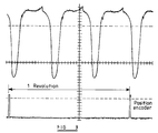
- the current dependent voltage waveform contains three basic components. Firstly there is a first component which has a frequency of six cycles per shaft revolution. The amplitude of this decreases from a maximum at high load to a minimum at no load. A second component has a frequency of only three cycles per shaft revolution and its amplitude increases from a minimum at high load to a maximum at no load. Finally, there is a third component which is a d.c. transient signal which arises from the motor being started and stopped.
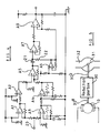
- the signal at terminal 20 is split into two paths.
- One path includes a d.c. level shifter and scaler based on two operational amplifiers A1 and A2.
- the other path provides similar level shifting and scaling functions, but also acts as a two stage low pass filter (as described hereinafter). It is based on two operational amplifiers A3 and A4.
- the outputs from the two paths are combined by a difference amplifier A5 so that transient d.c. shifts in the input signal and frequencies below an upper limit level are cancelled.
- This upper limit level is selected so that the trough component of the waveform is removed leaving the upper harmonics of the double-peaked waveform component intact.
- the filter characteristics of the second path is obtained by providing unity gain up to a first zero frequency, followed by amplification above that zero frequency.
- the filter circuit shown in Figure 4 has a fixed characteristic but it may have adjustable components variable under the control of the processor to raise and lower the filter cut off point according to motor speed.
Landscapes
- Engineering & Computer Science (AREA)
- Physics & Mathematics (AREA)
- General Physics & Mathematics (AREA)
- Human Computer Interaction (AREA)
- Manufacturing & Machinery (AREA)
- Automation & Control Theory (AREA)
- Control Of Direct Current Motors (AREA)
Applications Claiming Priority (4)
| Application Number | Priority Date | Filing Date | Title |
|---|---|---|---|
| GBGB9604274.2A GB9604274D0 (en) | 1996-02-29 | 1996-02-29 | Motor circuit |
| GB9604274 | 1996-02-29 | ||
| GBGB9620424.3A GB9620424D0 (en) | 1996-10-01 | 1996-10-01 | Motor circuit |
| GB9620424 | 1996-10-01 |
Publications (3)
| Publication Number | Publication Date |
|---|---|
| EP0793077A2 true EP0793077A2 (fr) | 1997-09-03 |
| EP0793077A3 EP0793077A3 (fr) | 1998-05-13 |
| EP0793077B1 EP0793077B1 (fr) | 2001-09-12 |
Family
ID=26308825
Family Applications (1)
| Application Number | Title | Priority Date | Filing Date |
|---|---|---|---|
| EP19970301313 Expired - Lifetime EP0793077B1 (fr) | 1996-02-29 | 1997-02-27 | Circuit pour la détection de la position d'un moteur électrique |
Country Status (2)
| Country | Link |
|---|---|
| EP (1) | EP0793077B1 (fr) |
| DE (1) | DE69706581T2 (fr) |
Cited By (1)
| Publication number | Priority date | Publication date | Assignee | Title |
|---|---|---|---|---|
| CN115552252A (zh) * | 2020-05-21 | 2022-12-30 | 意玛克股份公司 | 用于通过感应传感器的测量估算吸热马达以预定速度运行的时间的方法以及实施该方法的设备 |
Families Citing this family (1)
| Publication number | Priority date | Publication date | Assignee | Title |
|---|---|---|---|---|
| CH718623A2 (de) * | 2021-05-12 | 2022-11-15 | Oblamatik Ag | Verstelleinrichtung, motorisch angetriebenes Ventil und Verfahren zum Betreiben einer Verstelleinrichtung. |
Family Cites Families (3)
| Publication number | Priority date | Publication date | Assignee | Title |
|---|---|---|---|---|
| US3346725A (en) * | 1964-07-10 | 1967-10-10 | Gen Motors Corp | Commutator pulse counting apparatus |
| SE500651C2 (sv) * | 1989-01-20 | 1994-08-01 | Ambient Energy Design | Anordning för reglering av drivmotorn hos fönsterjalusier eller markiser |
| US5038247A (en) * | 1989-04-17 | 1991-08-06 | Delco Electronics Corporation | Method and apparatus for inductive load control with current simulation |
-
1997
- 1997-02-27 EP EP19970301313 patent/EP0793077B1/fr not_active Expired - Lifetime
- 1997-02-27 DE DE1997606581 patent/DE69706581T2/de not_active Expired - Lifetime
Cited By (1)
| Publication number | Priority date | Publication date | Assignee | Title |
|---|---|---|---|---|
| CN115552252A (zh) * | 2020-05-21 | 2022-12-30 | 意玛克股份公司 | 用于通过感应传感器的测量估算吸热马达以预定速度运行的时间的方法以及实施该方法的设备 |
Also Published As
| Publication number | Publication date |
|---|---|
| DE69706581D1 (de) | 2001-10-18 |
| DE69706581T2 (de) | 2002-07-11 |
| EP0793077A3 (fr) | 1998-05-13 |
| EP0793077B1 (fr) | 2001-09-12 |
Similar Documents
| Publication | Publication Date | Title |
|---|---|---|
| US5798624A (en) | Motor circuit | |
| HK89589A (en) | Locomotive governor control | |
| US4426604A (en) | Direct current fan with control means | |
| JP2006042453A (ja) | 直流モータの回転情報検出装置 | |
| EP1269620A1 (fr) | Systeme et procede de detection de defaut de moteur | |
| US3942114A (en) | Speed detector and indicator for DC motors | |
| EP0793077B1 (fr) | Circuit pour la détection de la position d'un moteur électrique | |
| US20150311839A1 (en) | Circuit for determining position of a movable member | |
| US8461786B2 (en) | Method and device for determining the position of a mobile closing part of a vehicle | |
| US6724164B2 (en) | Opening-and-closing member control device | |
| US5589749A (en) | Closed loop control system and method using back EMF estimator | |
| US8022653B2 (en) | Method and circuit arrangement for the electrical control and/or regulation of the movement of an electrically driven unit | |
| EP0400684A2 (fr) | Appareil de détection de l'angle de braquage des roues arrières d'un véhicule | |
| WO1996007127A9 (fr) | Systeme asservi et procede utilisant une estimation de force contre-electromotrice | |
| GB2290178A (en) | Device for operating an electric motor | |
| US5734240A (en) | Bidirectional DC motor | |
| EP0600465B1 (fr) | Appareil pour commander un véhicule à moteur électrique | |
| JPH08502329A (ja) | 電動機式駆動装置 | |
| KR20050018815A (ko) | 자동차 사이드미러의 제어장치 및 제어방법 | |
| US5130627A (en) | Method for positioning a part and device for carrying out the method | |
| EP0208142B1 (fr) | Dispositif de commande de vitesse d'un moteur | |
| JP3098879B2 (ja) | 磁束密度検出装置 | |
| CN119593666A (zh) | 惯性检测电路 | |
| US4808935A (en) | Electric set-point transmitter | |
| JP2542053Y2 (ja) | 変換器の異常判定回路 |
Legal Events
| Date | Code | Title | Description |
|---|---|---|---|
| PUAI | Public reference made under article 153(3) epc to a published international application that has entered the european phase |
Free format text: ORIGINAL CODE: 0009012 |
|
| AK | Designated contracting states |
Kind code of ref document: A2 Designated state(s): DE ES FR GB IT |
|
| PUAL | Search report despatched |
Free format text: ORIGINAL CODE: 0009013 |
|
| AK | Designated contracting states |
Kind code of ref document: A3 Designated state(s): DE ES FR GB IT |
|
| 17P | Request for examination filed |
Effective date: 19980919 |
|
| GRAG | Despatch of communication of intention to grant |
Free format text: ORIGINAL CODE: EPIDOS AGRA |
|
| 17Q | First examination report despatched |
Effective date: 20000925 |
|
| GRAG | Despatch of communication of intention to grant |
Free format text: ORIGINAL CODE: EPIDOS AGRA |
|
| GRAG | Despatch of communication of intention to grant |
Free format text: ORIGINAL CODE: EPIDOS AGRA |
|
| GRAH | Despatch of communication of intention to grant a patent |
Free format text: ORIGINAL CODE: EPIDOS IGRA |
|
| GRAH | Despatch of communication of intention to grant a patent |
Free format text: ORIGINAL CODE: EPIDOS IGRA |
|
| RAP1 | Party data changed (applicant data changed or rights of an application transferred) |
Owner name: KELSEY-HAYES COMPANY |
|
| GRAA | (expected) grant |
Free format text: ORIGINAL CODE: 0009210 |
|
| AK | Designated contracting states |
Kind code of ref document: B1 Designated state(s): DE ES FR GB IT |
|
| REF | Corresponds to: |
Ref document number: 69706581 Country of ref document: DE Date of ref document: 20011018 |
|
| ET | Fr: translation filed | ||
| REG | Reference to a national code |
Ref country code: GB Ref legal event code: IF02 |
|
| PG25 | Lapsed in a contracting state [announced via postgrant information from national office to epo] |
Ref country code: ES Free format text: LAPSE BECAUSE OF FAILURE TO SUBMIT A TRANSLATION OF THE DESCRIPTION OR TO PAY THE FEE WITHIN THE PRESCRIBED TIME-LIMIT Effective date: 20020326 |
|
| PLBE | No opposition filed within time limit |
Free format text: ORIGINAL CODE: 0009261 |
|
| STAA | Information on the status of an ep patent application or granted ep patent |
Free format text: STATUS: NO OPPOSITION FILED WITHIN TIME LIMIT |
|
| 26N | No opposition filed | ||
| PG25 | Lapsed in a contracting state [announced via postgrant information from national office to epo] |
Ref country code: IT Free format text: LAPSE BECAUSE OF NON-PAYMENT OF DUE FEES Effective date: 20100227 |
|
| PGRI | Patent reinstated in contracting state [announced from national office to epo] |
Ref country code: IT Effective date: 20110616 |
|
| REG | Reference to a national code |
Ref country code: FR Ref legal event code: PLFP Year of fee payment: 20 |
|
| PGFP | Annual fee paid to national office [announced via postgrant information from national office to epo] |
Ref country code: DE Payment date: 20160226 Year of fee payment: 20 Ref country code: IT Payment date: 20160223 Year of fee payment: 20 |
|
| PGFP | Annual fee paid to national office [announced via postgrant information from national office to epo] |
Ref country code: GB Payment date: 20160226 Year of fee payment: 20 Ref country code: FR Payment date: 20160217 Year of fee payment: 20 |
|
| REG | Reference to a national code |
Ref country code: DE Ref legal event code: R071 Ref document number: 69706581 Country of ref document: DE |
|
| REG | Reference to a national code |
Ref country code: GB Ref legal event code: PE20 Expiry date: 20170226 |
|
| PG25 | Lapsed in a contracting state [announced via postgrant information from national office to epo] |
Ref country code: GB Free format text: LAPSE BECAUSE OF EXPIRATION OF PROTECTION Effective date: 20170226 |