EP0793152A2 - Holographisches Abbildungs- und Anzeigegerät und Verfahren - Google Patents
Holographisches Abbildungs- und Anzeigegerät und Verfahren Download PDFInfo
- Publication number
- EP0793152A2 EP0793152A2 EP97301369A EP97301369A EP0793152A2 EP 0793152 A2 EP0793152 A2 EP 0793152A2 EP 97301369 A EP97301369 A EP 97301369A EP 97301369 A EP97301369 A EP 97301369A EP 0793152 A2 EP0793152 A2 EP 0793152A2
- Authority
- EP
- European Patent Office
- Prior art keywords
- imaging
- optical system
- light
- imaging optical
- image
- Prior art date
- Legal status (The legal status is an assumption and is not a legal conclusion. Google has not performed a legal analysis and makes no representation as to the accuracy of the status listed.)
- Granted
Links
- 238000003384 imaging method Methods 0.000 title claims abstract description 631
- 238000000034 method Methods 0.000 title claims description 23
- 230000003287 optical effect Effects 0.000 claims abstract description 471
- 238000001093 holography Methods 0.000 claims abstract description 176
- 230000001427 coherent effect Effects 0.000 claims description 12
- 230000002452 interceptive effect Effects 0.000 claims 2
- 230000001678 irradiating effect Effects 0.000 claims 1
- 238000004364 calculation method Methods 0.000 description 66
- 239000003086 colorant Substances 0.000 description 39
- 238000010586 diagram Methods 0.000 description 30
- 230000015654 memory Effects 0.000 description 13
- 230000005540 biological transmission Effects 0.000 description 10
- 230000006870 function Effects 0.000 description 8
- 230000002194 synthesizing effect Effects 0.000 description 7
- 238000011426 transformation method Methods 0.000 description 6
- NCGICGYLBXGBGN-UHFFFAOYSA-N 3-morpholin-4-yl-1-oxa-3-azonia-2-azanidacyclopent-3-en-5-imine;hydrochloride Chemical compound Cl.[N-]1OC(=N)C=[N+]1N1CCOCC1 NCGICGYLBXGBGN-UHFFFAOYSA-N 0.000 description 4
- 239000011521 glass Substances 0.000 description 4
- 239000004973 liquid crystal related substance Substances 0.000 description 4
- 230000010287 polarization Effects 0.000 description 4
- 230000009466 transformation Effects 0.000 description 4
- 230000004048 modification Effects 0.000 description 3
- 238000012986 modification Methods 0.000 description 3
- 239000013307 optical fiber Substances 0.000 description 2
- 230000001902 propagating effect Effects 0.000 description 1
- 230000003252 repetitive effect Effects 0.000 description 1
- 238000005070 sampling Methods 0.000 description 1
- 229920001169 thermoplastic Polymers 0.000 description 1
- 239000004416 thermosoftening plastic Substances 0.000 description 1
- 238000002834 transmittance Methods 0.000 description 1
Images


















Classifications
-
- G—PHYSICS
- G03—PHOTOGRAPHY; CINEMATOGRAPHY; ANALOGOUS TECHNIQUES USING WAVES OTHER THAN OPTICAL WAVES; ELECTROGRAPHY; HOLOGRAPHY
- G03H—HOLOGRAPHIC PROCESSES OR APPARATUS
- G03H1/00—Holographic processes or apparatus using light, infrared or ultraviolet waves for obtaining holograms or for obtaining an image from them; Details peculiar thereto
- G03H1/04—Processes or apparatus for producing holograms
- G03H1/0402—Recording geometries or arrangements
- G03H1/0404—In-line recording arrangement
-
- G—PHYSICS
- G03—PHOTOGRAPHY; CINEMATOGRAPHY; ANALOGOUS TECHNIQUES USING WAVES OTHER THAN OPTICAL WAVES; ELECTROGRAPHY; HOLOGRAPHY
- G03H—HOLOGRAPHIC PROCESSES OR APPARATUS
- G03H1/00—Holographic processes or apparatus using light, infrared or ultraviolet waves for obtaining holograms or for obtaining an image from them; Details peculiar thereto
- G03H1/22—Processes or apparatus for obtaining an optical image from holograms
-
- G—PHYSICS
- G03—PHOTOGRAPHY; CINEMATOGRAPHY; ANALOGOUS TECHNIQUES USING WAVES OTHER THAN OPTICAL WAVES; ELECTROGRAPHY; HOLOGRAPHY
- G03H—HOLOGRAPHIC PROCESSES OR APPARATUS
- G03H1/00—Holographic processes or apparatus using light, infrared or ultraviolet waves for obtaining holograms or for obtaining an image from them; Details peculiar thereto
- G03H1/22—Processes or apparatus for obtaining an optical image from holograms
- G03H1/2294—Addressing the hologram to an active spatial light modulator
-
- G—PHYSICS
- G03—PHOTOGRAPHY; CINEMATOGRAPHY; ANALOGOUS TECHNIQUES USING WAVES OTHER THAN OPTICAL WAVES; ELECTROGRAPHY; HOLOGRAPHY
- G03H—HOLOGRAPHIC PROCESSES OR APPARATUS
- G03H1/00—Holographic processes or apparatus using light, infrared or ultraviolet waves for obtaining holograms or for obtaining an image from them; Details peculiar thereto
- G03H1/04—Processes or apparatus for producing holograms
- G03H1/0443—Digital holography, i.e. recording holograms with digital recording means
- G03H2001/0454—Arrangement for recovering hologram complex amplitude
- G03H2001/0458—Temporal or spatial phase shifting, e.g. parallel phase shifting method
Definitions
- the present invention relates to a holography imaging apparatus for recording three-dimensional information of an object, and a holography display apparatus for reading out the three-dimensional information of an object from the holography imaging apparatus and displaying a three-dimensional image of the object.
- the holography technique includes a holography imaging technique for recording three-dimensional information of an object, and a holography display technique for reading out the three-dimensional information of an object recorded by the holography imaging technique and displaying the three-dimensional image of the object.
- the conventional holography technique is designed under the premises that the imaging device has a high resolution upon holography imaging, and most of holography imaging apparatuses use a high-resolution photography dryplate or thermoplastic as imaging devices.
- Prior art 1 corresponds to an example of a Fresnel type holography technique which does not use any lenses that are normally used in the holography imaging technique.
- an imaging lens is used so that the spatial resolution of a real image matches that of an imaging device, and a diaphragm is arranged immediately before the position of the object space of the imaging lens.
- Interference fringes bearing both the distance information in the optical axis direction and the position information in a direction perpendicular to the optical axis are sensed, and an image to be reconstructed is read out from the interference fringes.
- the angle object light and reference light make must fall within the range from 2 to 3°. If the angle object light and reference light make becomes large, the spacing between adjacent interference fringes becomes smaller than the resolution of the imaging device and, hence, the interference fringes cannot be sensed with high contrast.
- the pixel pitch and pixel size of the CCD as the imaging device are different from those of a spatial modulation device used in image reconstruction, and the optical system upon holography imaging is different from that upon reconstruction.
- the enlargement factor of the reconstructed display image essentially varies depending on the position.
- a holography imaging apparatus uses an optical system having a positive refractive power, e.g., a convex lens, to vary the field of view, and reflects the distance, in the optical axis direction, to the object on the spacing between adjacent interference fringes and the position, in a direction perpendicular to the optical axis direction, of the object on the distribution range of the interference fringes, so as to assure a required spacing between adjacent interference fringes.
- a positive refractive power e.g., a convex lens
- the apparatus has the reflection function of the distance, in the optical axis direction, to the object independently of the reflection function of the position, in the direction perpendicular to the optical axis direction, of the object, and adjusts the position, in the optical axis direction, of an imaging device, thereby suppressing generation of interference fringes, the spacing of which is smaller than the resolution of the imaging device.
- the holography imaging apparatus comprises (a) diaphragm means having an aperture for passing object light reflected by the object to be sensed as a result of irradiation of the light output from a first light source onto the object to be sensed, (b) a first imaging optical system arranged at a position corresponding to the focal plane of an object space of the diaphragm means, (c) an interference optical system for converting the coherent light output from a second light source into reference light as plane waves, and bringing the object light via the first imaging optical system and the reference light to interference, and (d) image sensing means, having an imaging surface perpendicular to the optical axis of the first imaging optical system at a position separated by a first distance from the focal plane of an image space of the first imaging optical system in the propagation direction of the reference light output from the first imaging optical system, for sensing an image formed by interference light output from the interference optical system, wherein the following relation holds: a ⁇ ⁇ f/p where ⁇ is the
- first and second light sources can be realized by a single light source.
- the apparatus may further comprise first moving means for changing the first distance.
- first moving means for changing the first distance.
- an optimal imaging position can be set in correspondence with the distance to the object to be sensed and the resolution of the imaging surface.
- the imaging result of the image sensing means may be either (i) the intensity of light on the imaging surface or (ii) the amplitude and phase of waves of light on the imaging surface.
- an intensity hologram is obtained
- a complex hologram is obtained.
- the complex hologram is obtained by a fringe scanning method.
- the object to be sensed is irradiated with light output from the first light source.
- the object light as the light reflected by the object to be sensed is input to the first imaging optical system via the aperture having the aperture size that satisfies relation (1) above.
- a principal ray that has passed through the focal point of the object space of the imaging optical system is output from the exit position of the first imaging optical system, which position is separated by a predetermined distance from the central axis (to be also simply referred to as an optical axis hereinafter) of the first imaging optical system, in correspondence with the incident angle to the first imaging optical system, and is perpendicularly incident on the imaging surface along an optical path parallel to the optical axis.
- the light that has passed through the aperture is converted into light propagating toward the imaging point upon having passed through the imaging optical system. Accordingly, wavefronts that have passed through the aperture become spherical waves that converge from the passing point of the imaging optical system to the imaging point, and become spherical waves that diverge after passing through the imaging point.
- coherent light output from the light source is input to the interference means (optical system).
- the interference means converts the coherent light output from the second light source into reference light as plane waves, and brings the object light via the imaging optical system and the reference light to interference.
- first and second light sources may be realized by a single light source, and light output from the light source may be split by a beam splitter into light to be irradiated onto the object to be sensed and the coherent light as a source of the reference light.
- the object spherical waves that have passed through the imaging optical system are brought to interference with plane waves having the same wavelength as that of the spherical wave, and interference waves are observed in a section perpendicular to the optical axis at a position behind the imaging optical system, the section becomes a cosine wave Fresnel zone plate having the principal ray as the center, and a line connecting the centers of cosine wave Fresnel zone plates at various positions is parallel to the optical axis.
- the distances, in the direction perpendicular to the optical axis, to bright points of the object to be sensed define the distribution range of interference fringes coming from the bright points.
- the distances, in the optical axis direction, to the bright points of the object to be sensed define the spacing between adjacent interference fringes of the cosine Fresnel zone plate.
- the imaging apparatus of the present invention adopts an aperture having an aperture size a that satisfies relation (1) above so as to suppress generation of interference fringes, the spacing of which is smaller than the spatial resolution of the image sensing means, i.e., the size (to be also referred to as a pitch hereinafter) p of the unit of an imaging device used in the image sensing means.
- the incident angle, ⁇ of object light at which interference fringes generated on the imaging device having the pitch p can be sensed at the Nyquist spacing or less must satisfy: ⁇ ⁇ sin -1 (( ⁇ /2)/p)
- the angle (to be also referred to as the incident angle to the imaging point hereinafter), ⁇ i, the object light and the optical axis make satisfies: ⁇ i ⁇ tan -1 (( ⁇ /2)/p) Since ⁇ > 0, the angle ⁇ i also satisfies: ⁇ i ⁇ sin -1 (( ⁇ /2)/p)
- the imaging apparatus of the present invention can sense interference fringes at the Nyquist spacing, and information can be stored with high reproducibility owing to the sampling theorem.
- unresolved interference fringes may be produced.
- the light amount of unresolved interference fringes is recognized as a DC component, and lowers the contrast of the resolved interference fringes. It is convenient and practical to select a rectangular or circular aperture.
- Fig. 1 is an explanatory view of the principle of the holography imaging apparatus of the present invention.
- the holography imaging apparatus of the present invention comprises (a) an imaging optical system 110 having a positive refractive power, (b) a diaphragm 210 having an aperture 211 at a position near the focal point of the object space of the imaging optical system 110, (c) an interference optical system 300 for bringing object light and reference light to interference, and (d) an imaging device 400 which has an imaging surface 410 perpendicular to the optical axis and senses interference fringes of interference light output from the interference optical system 300.
- object light rays from bright points (P1, P2, P3,%) of the object to be sensed pass through the aperture 211 and then enter the imaging optical system 110.
- a principal ray that has passed through the center of the aperture 211 i.e., the focal point of the object space of the imaging optical system 110
- the exit position of the imaging optical system which position is separated by a predetermined distance from the optical axis of the imaging optical system 110, in correspondence with the incident angle to the imaging optical system 110, and is perpendicularly incident on the imaging surface 410 along an optical path parallel to the optical axis.
- the light rays that have passed the aperture 211 are converted into light rays which propagate toward imaging points (Q1, Q2, Q3,...) corresponding to the bright points (P1, P2, P3,...) when they have passed through the imaging optical system 110.
- wavefronts that have passed through the aperture 211 become spherical waves that converge from their passing points of the imaging optical system 110 to the imaging points (Q1, Q2, Q3,%), and become spherical waves that diverge after passing through the imaging points (Q1, Q2, Q3,).
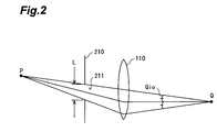
- Fig. 2 is an explanatory view of the incident angle of object light at the imaging point.
- the object light that has the bright point P as a start point and enters the imaging optical system 110 via the aperture 211 converges to the imaging point Q.
- the object light via the imaging optical system 110 and reference light (coherent light having the same wavelength as that of the object light) as plane waves enter the interference optical system 300 and brought to interference.
- the propagation direction of the reference light is set by the interference optical system so that the reference light via the interference optical system 300 propagates parallel to the optical axis and is perpendicularly incident on the imaging surface 410.
- the holography imaging apparatus of the present invention can sample at the Nyquist spacing or less interference fringes produced as a result of interference between the object light via the imaging optical system 110 and the reference light (coherent light having the same wavelength as that of the object light) in the interference optical system 300 since the incident angle at the imaging point always satisfies the condition given by relation (2) above.
- a holography display apparatus is a holography display apparatus for reconstructing and displaying an image of the object to be sensed on the basis of optical information sensed by the holography imaging apparatus of the present invention, and comprises (a) information input means for inputting the imaging result in the holography imaging apparatus of the present invention, (b) a hologram forming unit for forming a hologram on the imaging surface at the imaging timing of the holography imaging apparatus of the present invention on the basis of information supplied from the information input means, (c) a second imaging optical system which has a focal plane of the object space (the hologram site) at a position separated by the first direction in the holography imaging apparatus of the present invention from the position of the hologram in the average propagation direction of hologram forming light, and (d) 0th-order light shielding means arranged at the focal point of the image space of the second imaging optical system.
- the apparatus preferably further comprises second moving means for changing the distance between the position of the hologram and the focal plane of the object space of the second imaging optical system.
- second moving means for changing the distance between the position of the hologram and the focal plane of the object space of the second imaging optical system.
- the hologram forming means can be preferably constituted by optical members by comprising (i) display means for displaying an optical image of the imaging result supplied from the information input unit (means), (ii) a spatial light modulator in which a spatial light modulated image corresponding to the optical image displayed on the display means is written, (iii) a light source for producing read light to be irradiated onto the spatial light modulator, and (iv) a hologram forming optical system for receiving phase- or amplitude-modulated light obtained by phase- or amplitude-modulating the read light via the spatial light modulator, and forming a hologram having the same size as that of the imaging device of the holography imaging apparatus.
- the imaging result in the holography imaging apparatus of the present invention is a complex hologram that contains the amplitude information and phase information of incident light at the respective points on the imaging surface
- the hologram forming unit can be preferably constituted by optical members by comprising (i) a phase & amplitude modulation unit for phase- and amplitude-modulating incident light in accordance with the amplitude information and phase information supplied from the information input unit and outputting the modulated light, (ii) a light source for producing read light to be irradiated onto the phase & amplitude modulation unit, (iii) a hologram forming optical system for receiving phase- and amplitude-modulated light obtained by phase- and amplitude-modulating the read light via the phase & amplitude modulation unit, and forming a hologram having the same size as that of the imaging device of the holography imaging apparatus.
- the functions of the hologram forming unit, the second imaging optical system, and the 0th-order light shielding plate (means) can also be realized by calculation processing using a computer.
- the principle of hologram reconstruction utilized in the holography display apparatus of the present invention will be briefly described below.
- the holography display apparatus of the present invention reads out an interference fringe image sensed by the above-mentioned principle and displays a hologram.
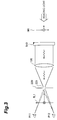
- Fig. 3 shows the arrangement of the most basic reconstruction optical system.
- this optical system comprises (a) an imaging optical system 120 equivalent to the imaging optical system 110 used in the imaging optical apparatus, (b) a complex hologram 510 arranged at a position corresponding to the imaging surface 410 with respect to the imaging optical system 110, i.e., on one focal plane of the imaging optical system 120, and (c) a diaphragm 220 which is arranged at a position corresponding to the diaphragm 210 with respect to the imaging optical system 110, i.e., on the other focal plane of the imaging optical system 120, and has an aperture 221 equivalent to the aperture 211.
- this reconstruction optical system when collimated light as conjugate waves of the reference light upon imaging, i.e., read light, is irradiated onto the complex hologram 510, light, the reconstruction wavefronts of which have an object image formed by the imaging optical system 110 upon imaging as a virtual image IM1, is produced. This light enters the imaging optical system 120 and forms a real image RL1 via the aperture 221 at a position corresponding to the position of the object to be sensed upon imaging.
- the real image RL1 is observed from a view point P11 or P12 located at the position behind the object to be sensed upon imaging. Hence, the image to be observed is the reverse site of the reconstructed image.
- the observer can only observe a portion of the real image RL1 associated with only reconstruction light incident on each view point.
- FIG. 3 shows the arrangement of a reconstruction optical system that can remove the drawbacks of the reconstruction optical system shown in Fig. 3.
- this reconstruction optical system comprises (a) an imaging optical system 120 equivalent to the imaging optical system 110 used in the imaging optical apparatus, (b) a complex hologram 510 which is arranged at a position corresponding to the imaging surface 410 with respect to the imaging optical system 110, i.e., on one focal plane of the imaging optical system 120, and is rotated through 180° about a direction perpendicular to the plane of the drawing of Fig. 4 as the rotation axis, and (c) a diaphragm 220 which is arranged at a position corresponding to the diaphragm 210 with respect to the imaging optical system 110, and has an aperture 221 equivalent to the aperture 211.
- this reconstruction optical system when collimated light as conjugate waves of the reference light upon imaging, i.e., read light, is irradiated onto the complex hologram 510, light, the reconstruction wavefronts of which form a real image RL2 at a symmetrical position with respect to the focal plane of the virtual image IM1, is produced.
- This light enters the imaging optical system 120, and is converted into light having wavefronts that form a virtual image IM2 between the imaging optical system 120 and the diaphragm 220.
- Fig. 5 shows the arrangement of the most basic reconstruction optical system of an intensity hologram. As shown in Fig. 5, this reconstruction optical system has substantially the same arrangement as that of the reconstruction optical system shown in Fig. 3, except that an intensity hologram 560 replaces the complex hologram 510.
- reconstruction light which has wavefronts that form a virtual image IM1 at the imaging position upon imaging as in the reconstruction optical system shown in Fig. 3, and wavefronts that form a virtual image RL3 at a symmetrical position of the virtual image IM1 about the intensity hologram 560 as the plane of symmetry, is produced.
- the light having the wavefronts that form the virtual image IM1 is reconstructed by the imaging optical system 120 as a real image RL1 at the position of the object to be sensed upon imaging.
- the light having the wavefronts that form the virtual image RL3 is reconstructed by the imaging optical system 120 as a virtual image IM3 at the symmetrical position of the real image RL1 about the diaphragm 220 as the plane of symmetry.
- the entire reconstructed image can be obtained.
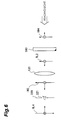
- Fig. 6 shows the arrangement of the reconstruction optical system that solves the problem of the reconstruction optical system shown in Fig. 5.
- this reproduction optical system has substantially the same arrangement as that of the system shown in Fig. 5, except that the intensity hologram 560 is arranged to be rotated through 180° about the direction perpendicular to the plane of the drawing of Fig. 6 as an axis.
- the light having the wavefronts that form the virtual image IM4 is reconstructed by the imaging optical system 120 as a real image RL4 at the position of the object to be sensed upon imaging.
- the light of the wavefronts that form the real image RL2 is reconstructed by the imaging optical system 120 as a virtual image IM2 at a symmetrical position of the real image RL4 about the diaphragm 220 as the plane of symmetry.
- the entire reconstructed image can be observed with the same directional relationship as that of the image upon imaging as in the reconstruction optical system shown in Fig. 4.
- the imaging surface is not set at the focal plane of the imaging optical system upon imaging.
- the imaging surface upon imaging is separated by z from the rear focal plane of the imaging optical system.
- Fig. 7 shows the arrangement of a reconstruction optical system in which the complex hologram 510 is set at the position of the imaging surface upon imaging in accordance with Fig. 3.
- the light having the wavefronts that form the virtual image IM1 is imaged by the imaging optical system 120 at the position of the object to be sensed upon imaging, thus reconstructing a real image RL1.
- the real image RL1 as the reconstructed image does not suffer any distortion upon imaging.
- the complex hologram 510 is rotated through 180° about the direction perpendicular to the plane of the drawing of Fig. 7 as an axis, and is moved by a distance y.
- a real image RL2 is reconstructed at the position, where the virtual image IM1 rotated through 180° about the same axis as the rotation axis of the complex hologram is reconstructed.
- Fig. 8 shows the arrangement of a reconstruction optical system that satisfies the condition given by equation (8).
- the image sensing means can comprise the imaging surface, which is separated by the first distance from the focal plane of the image space of the first imaging optical system in the propagation direction of the reference light output from the first imaging optical system, is arranged at the position where it does not receive any principal ray of light that comes from the object to be sensed and passes through the focal point of the object space of the first imaging optical system, and is perpendicular to the optical axis of the first imaging optical system.
- the holography display apparatus which reconstructs and displays the image of the object to be sensed on the basis of optical information sensed by the holography imaging apparatus, preferably further comprises principal ray shielding means which is arranged on the focal plane of the image space (opposite to the hologram site) of the second imaging optical system, and shields the principal ray of light having wavefronts that form a real image, which light is obtained by converting light having wavefronts, which form a hologram, via the second imaging optical system.
- Fig. 9 shows the arrangement of an imaging optical system suitable for removing a conjugate image upon reconstruction.
- this optical system comprises (a) an imaging optical system 110 having a positive refractive power, (b) a diaphragm 210 having an aperture 211 at a position near the focal point of the object space of the imaging optical system 110, (c) an interference optical system 300 for bringing object light and reference light to interference, and (d) an imaging device 400 which has an imaging surface 410 perpendicular to the optical axis, and senses interference fringes of interference light output from the interference optical system 300.
- the entire optical system is designed, so that the principal ray of object light that has passed through the focal point of the object space of the imaging optical system 100 is not incident on the imaging surface 410.
- Such arrangement can be attained by only the geometric arrangement of an object 900 to be sensed, the diaphragm 210, the imaging optical system 110, and the imaging surface 410, or can be attained by arranging a filter 419, the transmittance of which gradually becomes 0 at the incidence position, on the imaging surface 3410, of the principal ray of the object light that has passed through the focal point of the object space of the imaging optical system 110.
- a filter 419 the transmittance of which gradually becomes 0 at the incidence position, on the imaging surface 3410, of the principal ray of the object light that has passed through the focal point of the object space of the imaging optical system 110.
- interference fringes formed by object light that does not include any principal ray of the object light, which has passed through the focal point of the object space the imaging optical system 110, and the reference light, are sensed.
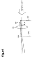
- Fig. 10 shows the arrangement of such reconstruction optical system. Note that Fig. 10 depicts the optical path of light suitable for observing the reconstructed image.
- this reconstruction optical system comprises (a) an imaging optical system 120 equivalent to the imaging optical system 110, a hologram 510 which is arranged at a position corresponding to the imaging surface 410 with respect to the imaging optical system 110, i.e., on one focal plane of the imaging optical system 120, and is rotated through 180° about the direction perpendicular to the plane of the drawing of Fig. 4 about the rotation axis, (c) a 0th-order light shielding plate 291 arranged near the focal point of the image space of the imaging optical system 120, and (d) a planar light shielding plate 292 arranged at a position below, on the plane of the drawing, the focal point of the image space of the imaging optical system 120.
- the layout position of the hologram 510 is the same as that in Fig. 8.
- the entire image in a normal image direction free from any distortion can be satisfactorily observed by observing this light, i.e., the virtual image IM2, from the position behind the focal plane of the image space of the imaging optical system 120.
- Fig. 11 is an explanatory view of removal of a conjugate image by the optical system shown in Fig. 10.
- Fig. 11 when collimated light as conjugate waves of the reference light upon imaging, i.e., read light is irradiated onto the hologram 510, light having wavefronts that form a virtual image IM1 as a conjugate image of a real image RL2 is produced as in Fig. 6.
- This light enters the imaging optical system 120, and is converted into light having wavefronts that form a real image RL1.
- Fig. 11 is an explanatory view of removal of a conjugate image by the optical system shown in Fig. 10.
- Fig. 12 is a diagram showing the arrangement of the first embodiment of a holography imaging apparatus according to the present invention.
- the holography imaging apparatus of this embodiment is an intensity recording type imaging apparatus.
- this apparatus comprises (a) a light source unit 610 for producing irradiation light to be irradiated onto an object 900 to be sensed and reference light, (b) a diaphragm 210 having an aperture 211 which transmits the object light reflected by the object 900 to be sensed as a result of irradiation of light output from the light source unit 610 onto the object 900 to be sensed, (c) an imaging optical system 110 arranged at a position corresponding to the focal plane of the object space of the diaphragm 210 and having a positive refractive index, (d) an interference optical system 310 for bringing the object light via the imaging optical system 110 and the reference light to interference, (e) an imaging sensing means 400 which has an imaging surface 410 perpendicular to the optical axis
- the light source unit 610 comprises (i) a laser light source 611 for producing coherent light, (ii) a beam splitter 612 for splitting light output from the laser light source 611 into two beams, (iii) a polarizer 613 for receiving one of the beams output from the beam splitter 612, selecting the direction of polarization, and outputting the polarized beam, (iv) an optical system 614 for outputting the light via the polarizer 613 toward the object 900 to be sensed as irradiation light of spherical waves, (v) a polarizer 615 for receiving the other beam output from the beam splitter 612, selecting the direction of polarization, and outputting the polarized beam, and (vi) an optical system 616 outputting the light via the polarizer 615 toward the interference optical system 310 as light of spherical waves.
- the interference optical system 310 comprises (i) an optical system 311 for receiving the light via the optical system 616 and converting it into plane waves, (ii) a mirror 312 for reflecting the light via the optical system 311 and setting an optical path, and (iii) a half mirror 313 for receiving the object light via the imaging optical system 110 and the reference light via the mirror 312, and outputting these two beams in substantially the same directions to bring them to interference.
- the image sensing means 400 comprises (i) an analyzer 430 for receiving interference light output from the interference optical system 310, selecting the direction of polarization, and outputting the light, (ii) an imaging device 420 which has the imaging surface 410 for receiving the light via the analyzer 430, and senses an optical image on the imaging surface 410, and (iii) a moving means 440 for moving the position of the imaging surface 410 relative to the interference optical system 310.
- the imaging device 420 adopts a CCD camera
- the camera is set in a direction so as to scan an image formed by the imaging optical system 110 to be inverted in the horizontal and vertical directions.
- an optical fiber plate having a core diameter equal to or smaller than the imaging resolution is preferably used in place of the normal protection glass.
- the object 900 is set at a position about 46.6 cm ahead of the imaging optical system 110.
- the imaging point of the object 900 to be sensed by the imaging optical system 110 corresponds to a position separated by 29.4 cm from the imaging optical system 110.
- optical axis of the object light is defined as the z-axis
- the up-and-down direction of the plane of the drawing of Fig. 12 is defined as the y-direction
- direction perpendicular to the plane of the drawing of Fig. 12 is defined as the x-direction.
- the holography imaging apparatus of this embodiment senses an intensity hologram of the object 900 to be sensed as follows.
- the imaging surface 410 is set at a position separated by an appropriate distance L from the object 900 to be sensed using the moving means 440 in accordance with the resolution of the image sensing means while maintaining the positional relationship between the diaphragm 210 and the imaging optical system 110 unchanged.
- the distance L can be obtained as follows.
- a cosine wave Fresnel zone plate F(x, y, L), produced on the imaging surface 410 by interference between spherical wave light after the object light as the irradiation light output from the light source unit 610 and reflected by the object 900 to be sensed has passed through the imaging optical system 110, and plane wave light obtained by converting the reference light output from the light source unit 610 into plane waves, is given by: F(x, y, L) 1 + cos((2 ⁇ / ⁇ ) (x 2 + y 2 + L 2 ) 1/2 )
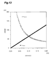
- the condition for resolving the cosine wave Fresnel zone plate F(x, y, L) up to a maximum of nth order by the imaging surface 410 having the resolution p is: r xyd (n) - r xyb (n) > p
- n maxp the maximum resolution order n maxp is as a function of the distance L, and is nearly inversely proportional to the distance L.
- r xyb (n) (N/2)p i.e., if n that roughly sets the position of the nth-order light portion at the two ends of the imaging surface 410 is assumed to be a maximum imaging order n maxd , the maximum imaging order n maxd is a function of the distance L and is proportional to the distance L.
- Fig. 13 is a graph showing the dependence of the maximum resolution order n maxp and the maximum imaging order n maxd on the distance L in this embodiment.
- n maxp n maxd
- n that satisfies the condition of equation (15) is 64, and an optimal distance Lopt is about 9.8 cm.
- the optimal distance Lopt can be set as the distance from the imaging point by the imaging optical system 110 to the imaging surface 410.
- the distance L is set to be larger than 9.8 cm, information that can be originally sensed cannot be received, but fringe information that can be resolved by the entire imaging surface can be received.
- the moving means 440 sets the distance L between the imaging point of the object 900 to be sensed and the imaging surface 410 to be 10 cm, i.e., sets the imaging surface 410 at a position separated by 19.4 cm from the imaging optical system 110.
- the light source unit 610 outputs irradiation light for the object 900 to be sensed, and reference light.
- the object 900 to be sensed irradiated with the irradiation light causes reflection, thus producing object light as spherical waves.
- Some light components of the object light enter the imaging optical system 110 via the aperture 211, are output toward the imaging point, and enter the interference optical system 310.
- the reference light output from the light source unit 610 enters the interference optical system 310 and interferes with the object light.
- Interference light output from the interference optical system 310 is received by the imaging surface 410 after the object light and the reference light are selected by the analyzer 430.
- a fringe image formed by the light received by the imaging surface 410 is sensed by the imaging device 420, and the imaging result is stored in the storage means 710 together with the information of the distance L or is transmitted from the transmission means 720 toward the holography display apparatus.
- a laser light source that can output the three primary colors of light in turn may be prepared as the laser light source 611, and holograms of the respective colors may be sensed in turn to acquire imaging information that can reconstruct a color image.
- laser devices which output the respective color beams may be prepared and be driven sequentially, or a laser light source which outputs light including the three primary colors of light may be prepared and filters each for selecting one of the three primary colors of light may be used in turn.
- Fig. 14 is a diagram showing the arrangement of the second embodiment of a holography imaging apparatus according to the present invention.
- the holography imaging apparatus of this embodiment is a complex hologram recording type holography imaging apparatus.
- this apparatus comprises (a) a light source unit 610 for producing irradiation light to be irradiated onto an object 900 to be sensed, and reference light, (b) a diaphragm 210 having an aperture 211 that transmits object light reflected by the object 900 to be sensed as a result of irradiation of the light output from the light source unit 610 onto the object 900 to be sensed, (c) an imaging optical system 110 arranged at a position corresponding to the focal plane of the object space of the diaphragm 210 and having a positive refractive index, (d) an interference optical system 320 for bringing the object light via the imaging optical system 110 and the reference light to interference, (e) an imaging sensing means 400 which has an imaging surface 410 perpen
- the interference optical system 320 comprises (i) an optical system 311 for receiving light via an optical system 616 and converting the light into plane waves, (ii) a phase adjuster 321 for receiving the light via the optical system 311, adjusting the phase of output light by the amount instructed from the processing unit 800, and outputting the adjusted light, (iii) a half mirror 322 for setting the optical path of light via the phase adjuster 321, and (iv) a half mirror 313 for receiving the object light via the imaging optical system 110 and the reference light via the half mirror 322, and outputting these two beams in substantially the same directions to bring them to interference.
- the phase adjuster 321 performs phase adjustment in four steps for every ⁇ /4.
- the phase adjuster 321 comprises (i) a mirror 326 for reflecting the incident light, and (ii) a piezoelectric device 327 for moving the mirror 326 in accordance with an instruction from the processing unit 800.
- Fig. 15 is a block diagram of the processing unit 800.
- the processing unit 800 comprises (i) frame memories 810 0 to 810 3 for storing light intensity data of the respective pixels on the imaging surface 410 in units of phase adjustment amounts, (ii) a calculation unit 820 for calculating the amplitudes and phases of object light at the respective pixel positions on the basis of the data of the pixels stored in the frame memories 810 0 to 810 3 , and (iii) a control unit 830 for controlling the frame memories 810 0 to 810 3 and the calculation unit 820, and issuing a phase adjustment instruction signal of the phase adjuster 321.
- the holography imaging apparatus of this embodiment senses a complex hologram as follows.
- the imaging surface 410 is set at a position separated by an appropriate distance L from the object 900 to be sensed using the moving means 440 in accordance with the resolution of the image sensing means while maintaining the positional relationship between the diaphragm 210 and the imaging optical system 110.
- the light source unit 610 outputs irradiation light for the object 900 to be sensed, and reference light.
- the object 900 to be sensed irradiated with the irradiation light causes reflection, thus producing object light as spherical waves.
- Some light components of the object light enter the imaging optical system 110 via the aperture 211, are output toward the imaging point, and enter the interference optical system 320.
- Interference light output from the interference optical system 320 is received by the imaging surface 410 after the object light and the reference light are selected by an analyzer 430.
- I 0 and I 2 are input to a subtracter 821 to calculate (I 0 - I 2 ), and (I 0 - I 2 ) is input to a synchronization register 823 and a divider 824.
- I 1 and I 3 are input to a subtracter 822 to calculate (I 1 - I 3 ), and (I 1 - I 3 ) is input to the divider 824.
- the divider 824 calculates (I 1 - I 3 )/(I 0 - I 2 ), and inputs the calculation result to an inverse tangent calculator 825.
- the inverse tangent calculator 825 executes the calculation of equation (23), inputs ( ⁇ O - ⁇ R ) as the calculation result to a cosine calculator 826, and outputs it as the first calculation result of the calculation unit 820 via a synchronization register 828.
- the cosine calculator 826 calculates 4A R cos( ⁇ O - ⁇ R ), and inputs the calculation result to a divider 827.
- the divider 827 receives the storage data (I 0 - I 2 ) in the register 823 in addition to the calculation result of the cosine calculator 826, and executes the calculation of equation (24).
- the amplitude A O of the object light as the calculation result is output as the second calculation result of the calculation unit 820.
- the calculation results of the calculation unit 820 are stored in the storage means 710 together with the information of the distance L or are transmitted from the transmission means 720 to the holography display apparatus.
- a laser light source that can output the three primary colors of light in turn may be prepared as the laser light source 611, and holograms of the respective colors may be sensed in turn to acquire imaging information that can reconstruct a color image.
- laser devices which output the respective color beams may be prepared and be driven sequentially, or a laser light source which outputs light including the three primary colors of light may be prepared and filters each for selecting one of the three primary colors of light may be used in turn.
- Fig. 16 is a diagram showing the arrangement of the third embodiment of a holography imaging apparatus according to the present invention.
- this apparatus comprises (a) a light source unit 610 for producing irradiation light to be irradiated onto an object 900 to be sensed present above an optical axis LL on the plane of the drawing of Fig.
- a diaphragm 210 having an aperture 211 which transmits the object light reflected by the object 900 to be sensed as a result of irradiation of light output from the light source unit 610 onto the object 900 to be sensed, (c) an imaging optical system 110 arranged at a position corresponding to the focal plane of the object space of the diaphragm 210 and having a positive refractive index, (d) an interference optical system 310 for bringing the object light via the imaging optical system 110 and the reference light to interference, (e) an image sensing means 480 which has an imaging surface 410 perpendicular to the optical axis of the imaging optical system 110 and senses an image formed by interference light output from the interference optical system 310, (f) a storage means 710 for receiving and storing imaging information output from the image sensing means 480, and (g) a transmission means 720 for receiving the imaging information output from the image sensing means 400 and transmitting it to a holography display apparatus.
- the image sensing means 480 comprises (i) an analyzer 430 for receiving interference light output from the interference optical system 310, selecting the direction of polarization, and outputting the light, (ii) an imaging device 420 which has the imaging surface 410 for receiving the light via the analyzer 430, and senses an optical image on the imaging surface 410, (iii) an image processing unit 450 for extracting the imaging result on the imaging surface 410 only below the optical axis LL in the plane of the drawing of Fig. 16, and (iv) a moving means 440 for moving the position of the imaging surface 410 relative to the interference optical system 300.
- the image processing unit 450 comprises (i) an image memory 451 for storing a pixel effective value (e.g., 1) in an area corresponding to the lower region in the plane of the drawing of the imaging surface 410, storing a pixel non-effective value (e.g., 0) in an area corresponding to the upper region in the plane of the drawing of the imaging surface 410, and outputting pixel effective/non-effective signals for the respective pixels, and (ii) a multiplier 452 for calculating the products between pixel signals output from the imaging device 420 and the pixel effective/non-effective signals corresponding to the pixel positions output from the image memory 451, and outputting the product values.
- a pixel effective value e.g., 1
- a pixel non-effective value e.g., 0
- the pixel effective/non-effective values are not only expressed by binary values but may be smoothly changed in the vicinity of the boundary to prevent generation of a diffraction image at end points.
- the object 900 is set at the position about 46.6 cm ahead of the imaging optical system 110, as in the first embodiment.
- the imaging point of the object 900 to be sensed by the imaging optical system 110 corresponds to a position separated by 29.4 cm from the imaging optical system 110.
- optical axis of the object light is defined as the z-axis
- the up-and-down direction of the plane of the drawing of Fig. 16 is defined as the y-direction
- direction perpendicular to the plane of the drawing of Fig. 16 is defined as the x-direction, as in the first embodiment.
- the holography imaging apparatus of this embodiment senses an intensity hologram of the object 900 to be sensed as follows.
- the imaging surface 410 is set at a position separated by an appropriate distance L from the object 900 to be sensed using the moving means 440 in accordance with the resolution of the image sensing means while maintaining the positional relationship between the diaphragm 210 and the imaging optical system 110 unchanged.
- the distance L can be obtained in the same manner as in the first embodiment.
- the light source unit 610 outputs irradiation light for the object 900 to be sensed, and reference light.
- the object 900 to be sensed irradiated with the irradiation light causes reflection, thus producing object light as spherical waves.
- Some light components of the object light enter the imaging optical system 110 via the aperture 211, are output toward the imaging point, and enter the interference optical system 310.
- the reference light output from the light source unit 610 enters the interference optical system 310 and interferes with the object light.
- Interference light output from the interference optical system 310 is received by the imaging surface 410 after the object light and the reference light are selected by the analyzer 430.
- a fringe image formed by the light received by the imaging surface 410 is sensed by the imaging device 420, and the imaging result is stored in the storage means 710 together with the information of the distance L or is transmitted from the transmission means 720 toward the holography display apparatus.
- a laser light source that can output the three primary colors of light in turn may be prepared as a laser light source 611, and holograms of the respective colors may be sensed in turn to acquire imaging information that can reconstruct a color image.
- laser devices which output the respective color beams may be prepared and be driven sequentially, or a laser light source which outputs light including the three primary colors of light may be prepared and filters each for selecting one of the three primary colors of light may be used in turn.
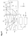
- Fig. 17 is a diagram showing the arrangement of the fourth embodiment of a holography imaging apparatus according to the present invention.
- the holography imaging apparatus of this embodiment is an intensity recording type imaging apparatus.
- this apparatus comprises (a) a light source unit 610 for producing irradiation light to be irradiated onto an object 900 to be sensed and reference light, (b) a diaphragm 210 having an aperture 211 which transmits the object light reflected by the object 900 to be sensed as a result of irradiation of light output from the light source unit 610 onto the object 900 to be sensed, (c) an imaging optical system 110 having a variable focal length, arranged at a position corresponding to the focal plane of the object space of the diaphragm 210 and having a positive refractive index, (d) an interlocking means 270 for setting the focal length of the imaging optical system 110, and changing the distance between the diaphragm 210 and the imaging optical system 110 and the aperture size of the
- Fig. 18 is a view showing the arrangement of the imaging optical system 110.
- the interlocking means 270 comprises (i) a holder 271 for the convex lens 111, which holder has a collapsible pin 271 1 , (ii) a holder 272 for the convex lens 112, which holder has a collapsible pin 272 1 , (iii) a holder 273 for the diaphragm 210, which holder has a collapsible pin 273 1 and a collapsible lever 273 2 for controlling the aperture size, and (iv) an intermediate holder 274 which has collapsible pins 274 1 and 274 2 , houses the holders 271, 272, and 273, and also has a notch 274 3 for limiting the movements of the collapsible pins 271 1 , 272 1 , and 273 1 in the horizontal direction, and a notch 274 4 for allowing the movement of the collap
- the interlocking means 270 comprises an external holder 275 6 which houses the intermediate holder 274, and has a notch 275 1 for limiting the movement of the collapsible pin 274 1 to rotation about the optical axis, a notch 275 2 for limiting the movement of the collapsible pin 274 2 to rotation about the optical axis, a notch 275 3 for limiting the movement of the collapsible pin 274 1 , a notch 275 4 for limiting the movement of the collapsible pin 272 1 , a notch 275 5 for limiting the movement of the collapsible pin 273 1 , and a notch 275 6 for limiting the movement of the collapsible lever 273 2 .
- the intersections between the notch 274 3 , and notches 275 3 , 275 4 , and 275 5 define the horizontal positions of the aperture 210 and the convex lenses 111 and 112.
- the notch 275 6 defines the position of the collapsible lever 273 2 to define the aperture size of the aperture 211 of the diaphragm 210.
- Fig. 20 shows the relationship among the distances L1, L2, and L3, the synthesize focal length f, and the rotation angle 8 when the above-mentioned numerical values are set.
- Fig. 21 shows the relationship between the rotation angles ⁇ m and ⁇ when the above-mentioned numerical values are set.
- the object 900 is set at a position about 46.4 cm ahead of the imaging optical system 110, as in the first embodiment.
- the imaging point of the object 900 to be sensed by the imaging optical system 110 corresponds to a position separated by 29.4 cm from the imaging optical system 110.
- optical axis of the object light is defined as the z-axis
- the up-and-down direction of the plane of the drawing of Fig. 17 is defined as the y-direction
- direction perpendicular to the plane of the drawing of Fig. 17 is defined as the x-direction, as in the first embodiment.
- the holography imaging apparatus of this embodiment senses an intensity hologram of the object 900 to be sensed as follows.
- the interlocking means sets the positions of the diaphragm 210 and the imaging optical system 110 in correspondence with the resolution of the image sensing means, so that the imaging surface 410 is separated by an appropriate distance L from the object 900 to be sensed.
- the distance L can be obtained in the same manner as in the first embodiment.
- the interlocking means 270 sets the distance L between the imaging point of the object 900 to be sensed and the imaging surface 410 to be 10 cm, i.e., sets the imaging surface 410 to be separated by 19.4 cm from the imaging optical system 110.
- the light source unit 610 outputs irradiation light for the object 900 to be sensed, and reference light.
- the object 900 to be sensed irradiated with the irradiation light causes reflection, thus producing object light as spherical waves.
- Some light components of the object light enter the imaging optical system 110 via the aperture 211, are output toward the imaging point, and enter the interference optical system 310.
- the reference light output from the light source unit 610 enters the interference optical system 310 and interferes with the object light.
- Interference light output from the interference optical system 310 is received by the imaging surface 410 after the object light and the reference light are selected by the analyzer 430.
- a fringe image formed by the light received by the imaging surface 410 is sensed by the imaging device 420, and the imaging result is stored in the storage means 710 together with the information of the distance L or is transmitted from the transmission means 720 toward the holography display apparatus.
- a laser light source that can output the three primary colors of light in turn may be prepared as a laser light source 611, and holograms of the respective colors may be sensed in turn to acquire imaging information that can reconstruct a color image.
- laser devices which output the respective color beams may be prepared and be driven sequentially, or a laser light source which outputs light including the three primary colors of light may be prepared and filters each for selecting one of the three primary colors of light may be used in turn.
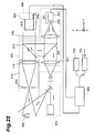
- Fig. 22 is a diagram showing the arrangement of the fifth embodiment of a holography imaging apparatus according to the present invention.
- the holography imaging apparatus of this embodiment is a complex hologram recording type holography imaging apparatus.
- this apparatus comprises (a) a light source unit 610 for producing irradiation light to be irradiated onto an object 900 to be sensed and reference light, (b) a diaphragm 210 having an aperture 211 which transmits the object light reflected by the object 900 to be sensed as a result of irradiation of light output from the light source unit 610 onto the object 900 to be sensed, (c) an imaging optical system 110 arranged at a position corresponding to the focal plane of the object space of the diaphragm 210 and having a positive refractive index, (d) an interlocking means 270 for setting the focal length of the imaging optical system 110, and changing the distance between the diaphragm 210 and the imaging optical system 110 and the aperture size of the
- the interference optical system 320 comprises (i) an optical system 311 for receiving the light via an optical system 616 and converting it into plane waves, (ii) a phase adjuster 321 for receiving the light via the optical system 311, adjusting the phase of output light by the amount instructed from the processing unit 800, and outputting the adjusted light, (iii) a half mirror 322 for setting the optical path of light via the phase adjuster 321, and (iv) a half mirror 313 for receiving the object light via the imaging optical system 110 and the reference light via the half mirror 322, and outputting these two beams in substantially the same directions to bring them to interference.
- the phase adjuster 321 performs phase adjustment in four steps for every ⁇ /4.
- the phase adjuster 321 comprises (i) a mirror 326 for reflecting the incident light, and (ii) a piezoelectric device 327 for moving the mirror 326 in accordance with an instruction from the processing unit 800.
- Fig. 23 is a block diagram showing the arrangement of the processing unit 800.
- the processing unit 800 comprises (i) frame memories 810 0 to 810 3 for storing light intensity data of the respective pixels on the imaging surface 410 in units of phase adjustment amounts, (ii) a calculation unit 820 for calculating the amplitudes and phases of object light at the respective pixel positions on the basis of the data of the pixels stored in the frame memories 810 0 to 810 3 , and (iii) a control unit 830 for controlling the frame memories 810 0 to 810 3 and the calculation unit 820, and issuing a phase adjustment instruction signal of the phase adjuster 321.
- the holography imaging apparatus of this embodiment senses a complex hologram as follows.
- a moving means 440 sets the imaging surface 410 at a position separated by an appropriate distance L from the object 900 to be sensed in correspondence with the resolution of the image sensing means while the interlocking means 270 maintains the positional relationship between the diaphragm 210 and the imaging optical system 110 unchanged.
- the light source unit 610 outputs irradiation light for the object 900 to be sensed, and reference light.
- the object 900 to be sensed irradiated with the irradiation light causes reflection, thus producing object light as spherical waves.
- Some light components of the object light enter the imaging optical system 110 via the aperture 211, are output toward the imaging point, and enter the interference optical system 320.
- Interference light output from the interference optical system 320 is received by the imaging surface 410 after the object light and the reference light are selected by an analyzer 430.
- phase ( ⁇ O - ⁇ R ) is output as the first calculation result of the calculation unit 820, and the amplitude A O of the object light is output as the second calculation result of the calculation unit 820.
- the calculation results of the calculation unit 820 are stored in the storage means 710 together with the information of the distance L or are transmitted from the transmission means 720 to the holography display apparatus.
- a laser light source that can output the three primary colors of light in turn may be prepared as the laser light source 611, and holograms of the respective colors may be sensed in turn to acquire imaging information that can reconstruct a color image.
- laser devices which output the respective color beams may be prepared and be driven sequentially, or a laser light source which outputs light including the three primary colors of light may be prepared and filters each for selecting one of the three primary colors of light may be used in turn.
- Fig. 24 is a diagram showing the first embodiment of a holography display apparatus according to the present invention.
- the holography display apparatus of this embodiment is an apparatus for reconstructing the image of an object 900 to be sensed on the basis of the intensity hologram sensed by the holography imaging apparatus shown in Fig. 12.
- this apparatus comprises (a) an information input unit 750 for receiving the hologram information sensed by the holography imaging apparatus shown in Fig. 12, (b) a hologram forming unit 650 for receiving the hologram information via the information input unit 750, and forming a hologram 511 on the basis of the received hologram information, (c) an imaging optical system 120 which is equivalent to the imaging optical system 110 in Fig. 12, and forms an image by receiving light of wavefronts that form the hologram 511, (d) a moving means 150 for changing the distance between the hologram 511 and the imaging optical system 120, and (e) a 0th-order light shielding plate 250 arranged at the focal point position of the image space of the imaging optical system 120.
- the information input unit 750 comprises (i) an information reading device 751 for reading out stored information from a storage medium of the imaging result of the holography imaging apparatus, and (ii) a receiver 752 for receiving the imaging result transmitted from the holography imaging apparatus.
- the hologram forming unit 650 comprises (i) a display device 651 for displaying an image on the basis of information supplied from the information input unit 750, (ii) a spatial light modulator 652 for writing the image displayed on the display device 651, (iii) a laser light source 653 for generating coherent light as plane waves to be irradiated onto the spatial light modulator 652, (iv) a relay optical system 654 for guiding the light output from the laser light source 653 to the spatial light modulator 652, and (v) an afocal optical system 655 for receiving the light phase-modulated by the spatial light modulator 652 and forming the hologram 511 of the spatial light modulator 652 that matches the size on the imaging surface upon imaging.
- an optical fiber plate having a core diameter equal to or smaller than the imaging resolution is preferably used in place of the normal protection glass.
- This holography display apparatus reconstructs and displays the image of the object to be sensed as follows on the basis of the imaging result of the holography imaging apparatus shown in Fig. 12.
- Image information as hologram information is received from the information input unit 750, and is displayed on the display device 651.
- the displayed image information is written in the spatial light modulator 652.
- the display device 651 preferably comprises a compact CRT, and the spatial light modulator 652 preferably comprises an optical writing type liquid crystal spatial light modulation device. Note that the display device 651 displays the imaging result while rotating it through 180° about the optical axis (z-axis).
- the light phase-modulated by the spatial light modulator 652 forms the hologram 511 of the spatial light modulator 652 via the afocal optical system 655 to have the same size as that upon imaging.
- the magnification of the afocal optical system is determined by the ratio of the pixel size of the display device 651 to that upon imaging. For example, when the display device 651 uses a 1.5" compact CRT, the pixel size is about 40 ⁇ m, and the pixel size upon imaging is 11 ⁇ m as described above. Hence, an afocal optical system of about 4 : 1 is used.
- a real image RL2 reconstructed by the hologram 511 is reproduced at the position, on the imaging optical system 120, of the hologram 511 and separated by about 6.6 cm from the imaging optical system 120.
- wavefronts that form the real image RL2 are those that form a virtual image IM2 by the imaging optical system 120.
- the 0th-order light shielding plate 250 set at the focal point position of the imaging optical system 120 shields 0th-order light components of the light output from the imaging optical system 120, and transmits light components of the 1st order or higher.
- the reconstructed image of the object 900 to be sensed free from any distortion can be observed.
- the color image of the object 900 to be sensed can be reconstructed by synthesizing the reconstructed images in units of colors as in the above embodiments.
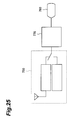
- Fig. 25 is a diagram showing the second embodiment of a holography display apparatus according to the present invention.
- the holography display apparatus of this embodiment is an apparatus for reconstructing the image of an object 900 to be sensed on the basis of an intensity hologram sensed by the holography imaging apparatus shown in Fig. 12.
- this apparatus comprises (a) an information input unit 750 for receiving the hologram information sensed by the holography imaging apparatus shown in Fig. 12, (b) a calculation unit 770 for receiving the hologram information via the information input unit 750, and calculating the reconstructed image of the object 900 to be sensed on the basis of the received hologram information, and (c) a display device 790 for displaying the calculation result of the calculation unit 770.
- the calculation unit 770 uses a computer that has function calculation performance.
- This holography display apparatus reconstructs and displays the image of the object to be sensed as follows on the basis of the imaging result of the holography imaging apparatus shown in Fig. 12.
- Fig. 26 is a flow chart showing the calculation processing of the calculation unit 770 of this embodiment.
- the calculation unit 770 receives hologram information from the information input unit. Subsequently, the object to be calculated is determined to be either the amplitude or phase, and is separated into a real number part and an imaginary number part to obtain a complex number distribution H(x, y).
- Wavefronts from the imaginarily set hologram are Fresnel-transformed to calculate those on the focal plane of the object space (to be also referred to as the near side hereinafter) of the imaginary imaging optical system.
- wavefronts Of(h p m, h p n) on the focal plane on the near side are calculated by:
- the sign of the Fresnel propagation direction is defined so that the direction from the hologram toward the imaginary imaging optical system is positive, and whether the direction to observe the focal plane on the near side from the hologram is positive or negative is discriminated.
- the wavefronts Of(h p m, h p n) are directly used; when it is negative, complex conjugates of wavefronts Of(h p m, h p n) are adopted to match the propagation direction of the wavefronts.
- the adopted wavefronts on the focal plane on the near side are subjected to two-dimensional Fourier transformation to calculate wavefronts G(f p m, f p n) on the focal plane of the image space (to be also referred to as the far side hereinafter) of the imaginary imaging optical system.
- f p is the pixel pitch on the focal plane on the far side.
- the wavefronts G(f p m, f p n) subjected to the 0th-order light shielding processing are subjected to inverse Fresnel transformation to calculate and obtain the wavefront distribution of the virtual image IM2.
- the distance, L 0 , between the focal point on the far side and the virtual image IM2 is 28.4 cm.
- wavefronts O(o p m, o p n) on the virtual image IM2 are calculated by:
- the wavefronts O(o p m, o p n) or O(f p m, f p n) are transformed, and the reconstructed image of the object to be sensed is displayed on the display device 790.
- a color image can be reconstructed by performing the calculations for the respective colors, and synthesizing the final reconstructed images.
- Fig. 27 is a diagram showing the third embodiment of a holography display apparatus according to the present invention.
- the holography display apparatus of this embodiment is an apparatus for reconstructing the image of an object 900 to be sensed on the basis of a complex hologram sensed by the holography imaging apparatus in Fig. 14.
- this apparatus comprises (a) an information input unit 750 for receiving the hologram information sensed by the holography imaging apparatus shown in Fig. 14, (b) a hologram forming unit 660 for receiving the hologram information via the information input unit 750, and forming a hologram 511 on the basis of the received hologram information, (c) an imaging optical system 120 which is equivalent to the imaging optical system 110 in Fig. 14, and forms an image by receiving light of wavefronts that form the hologram 511, (d) a moving means 150 for changing the distance between the hologram 511 and the imaging optical system 120, and (e) a 0th-order light shielding plate 250 arranged at the focal point position of the image space of the imaging optical system 120.
- the hologram forming unit 660 comprises (i) a phase & amplitude modulation unit 663 having a phase modulator 661 for modulating the phase of input light based on phase information supplied from the information input unit 750, and an amplitude modulator 662 for modulating the amplitude of input light, (ii) a laser light source 653 for producing coherent light as plane waves to be irradiated onto the phase & amplitude modulation unit 663, (iii) a relay optical system 654 for guiding light output from the laser light source 653 toward the phase modulator 661 and amplitude modulator 662, and (iv) an afocal optical system 655 for receiving light via the phase & amplitude modulation unit 663, and forming the hologram 511 of the phase & amplitude modulation unit 663 that matches the size on the imaging surface upon imaging.
- This holography display apparatus reconstructs and displays the image of the object to be sensed as follows on the basis of the imaging result of the holography imaging apparatus shown in Fig. 14.
- the light output from the laser light source 653 is irradiated onto the phase & amplitude modulation unit 663 via the relay optical system 654.
- the phase & amplitude modulation unit 663 receives phase information and amplitude information as hologram information from the information input unit 750, and the phase and amplitude modulators 661 and 662 respectively execute phase and amplitude modulation.
- the phase and amplitude modulators 661 and 662 can be easily realized using liquid crystal panels using the techniques disclosed in Japanese Patent Laid-Open Nos. 5-127139 and 5-119341.
- the light phase-modulated by the phase modulator 661 forms the hologram 511 of the phase modulator 661, which has the same size as that upon imaging, via the afocal optical system 655.
- the magnification of the afocal optical system is determined by the ratio of the pixel size of the display device 651 to that upon imaging.
- a real image RL2 reconstructed by the hologram 511 is reproduced at the position, on the imaging optical system 120, of the hologram 511 and separated by about 6.6 cm from the imaging optical system 120.
- wavefronts that form the real image RL2 are those that form a virtual image IM2 by the imaging optical system 120.
- the 0th-order light shielding plate 250 set at the focal point position of the imaging optical system 120 shields 0th-order light components of the light output from the imaging optical system 120, and transmits light components of the 1st order or higher.
- the reconstructed image of the object 900 to be sensed free from any distortion can be observed.
- the 0th-order light shielding plate 250 is not always required.
- the color image of the object 900 to be sensed can be reconstructed by synthesizing the reconstructed images in units of colors as in the above embodiments.
- Fig. 28 is a diagram showing the fourth embodiment of a holography display apparatus according to the present invention.
- the holography display apparatus of this embodiment is an apparatus for reconstructing the image of an object 900 to be sensed on the basis of a complex hologram sensed by the holography imaging apparatus shown in Fig. 14.
- this apparatus comprises (a) an information input unit 750 for receiving the hologram information sensed by the holography imaging apparatus shown in Fig. 14, (b) a calculation unit 780 for receiving the hologram information via the information input unit 750, and calculating the reconstructed image of the object 900 to be sensed on the basis of the received hologram information, and (c) a display device 790 for displaying the calculation result of the calculation unit 780.
- the calculation unit 780 uses a computer that has function calculation performance.
- This holography display apparatus reconstructs and displays the image of the object to be sensed as follows on the basis of the imaging result of the holography imaging apparatus shown in Fig. 14.
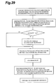
- Fig. 29 is a flow chart showing the calculation processing of the calculation unit 770 of this embodiment.
- the calculation unit 780 receives hologram information from the information input unit. Subsequently, each of the phase information and amplitude information of the object to be calculated is separated into a real number part and an imaginary number part to obtain a complex number distribution H(x, y).
- Fig. 30 is a diagram showing the fifth embodiment of a holography display apparatus according to the present invention.
- the holography display apparatus of this embodiment is an apparatus for reconstructing the image of an object 900 to be sensed on the basis of an intensity hologram sensed by the holography imaging apparatus in Fig. 16.
- this apparatus comprises (a) an information input unit 750 for receiving the hologram information sensed by the holography imaging apparatus shown in Fig. 16, (b) a hologram forming unit 650 for receiving the hologram information via the information input unit 750, and forming a hologram 511 on the basis of the received hologram information, (c) an imaging optical system 120 which is equivalent to the imaging optical system 110 in Fig.
- This holography display apparatus reconstructs and displays the image of the object to be sensed as follows on the basis of the imaging result of the holography imaging apparatus shown in Fig. 16.
- Image information as hologram information is received from the information input unit 750, and is displayed on a display device 651.
- the displayed image information is written in a spatial light modulator 652.
- the display device 651 preferably comprises a compact CRT, and the spatial light modulator 652 preferably comprises an optical writing type liquid crystal spatial light modulation device. Note that the display device 651 displays the imaging result while rotating it through 180° about the optical axis (z-axis).
- a laser light source 653 is irradiated onto the spatial light modulator 652 via a relay optical system 654.
- the light phase-modulated by the spatial light modulator 652 forms the hologram 511 of the spatial light modulator 652 via an afocal optical system 655 to have the same size as that upon imaging.
- the magnification of the afocal optical system is determined by the ratio of the pixel size of the display device 651 to that upon imaging. For example, when the display device 651 uses a 1.5" compact CRT, the pixel size is about 40 ⁇ m, and the pixel size upon imaging is 11 ⁇ m as described above. Hence, an afocal optical system of about 4 : 1 is used.
- a real image RL2 reconstructed by the hologram 511 is reproduced at the position, on the imaging optical system 120, of the hologram 511 and separated by about 6.6 cm from the imaging optical system 120.
- wavefronts that form the real image RL2 are those that form a virtual image IM2 by the imaging optical system 120.
- the 0th-order light shielding plate 251 set at the focal point position of the imaging optical system 120 shields 0th-order light components of the light output from the imaging optical system 120, and the light shielding plate 252 shields light of wavefronts that form a conjugate image of the virtual image IM2.
- the reconstructed image of the object 900 to be sensed free from any distortion can be observed.
- the color image of the object 900 to be sensed can be reconstructed by synthesizing the reconstructed images in units of colors as in the above embodiments.
- Fig. 31 is a diagram showing the sixth embodiment of a holography display apparatus according to the present invention.
- the holography display apparatus of this embodiment is an apparatus for reconstructing the image of an object 900 to be sensed on the basis of an intensity hologram sensed by the holography imaging apparatus shown in Fig. 16.
- this apparatus comprises (a) an information input unit 750 for receiving the hologram information sensed by the holography imaging apparatus shown in Fig. 16, (b) a calculation unit 770 for receiving the hologram information via the information input unit 750, and calculating the reconstructed image of the object 900 to be sensed on the basis of the received hologram information, and (c) a display device 790 for displaying the calculation result of the calculation unit 770.
- the calculation unit 770 uses a computer that has function calculation performance.
- This holography display apparatus reconstructs and displays the image of the object to be sensed as follows on the basis of the imaging result of the holography imaging apparatus shown in Fig. 16.
- Fig. 32 is a flow chart showing the calculation processing of the calculation unit 770 of this embodiment.
- the calculation unit 770 receives hologram information from the information input unit. Subsequently, the object to be calculated is determined to be either the amplitude or phase, and is separated into a real number part and an imaginary number part to obtain a complex number distribution H(x, y).
- Wavefronts from the imaginarily set hologram are Fresnel-transformed to calculate those on the focal plane of the object space (to be also referred to as the near side hereinafter), of the imaginary imaging optical system.
- a spherical wave reconstruction method and a fast Fourier transformation method are available, as in the second embodiment.
- the sign of the Fresnel propagation direction is defined so that the direction from the hologram toward the imaginary imaging optical system is positive, and whether the direction to observe the focal plane on the near side from the hologram is positive or negative is discriminated.
- the wavefronts Of(h p m, h p n) are directly used; when it is negative, complex conjugates of wavefronts Of(h p m, h p n) are adopted to match the propagation direction of the wavefronts.
- the adopted wavefronts on the focal plane on the near side are subjected to two-dimensional Fourier transformation to calculate wavefronts G(f p m, f p n) on the focal plane of the image space (to be also referred to as the far side hereinafter) of the imaginary imaging optical system.
- f p is the pixel pitch on the focal plane on the far side.
- the wavefronts G(f p m, f p n) subjected to the 0th-order light shielding processing are subjected to inverse Fresnel transformation to calculate and obtain the wavefront distribution of the virtual image IM2.
- the distance, L 0 , between the focal point on the far side and the virtual image IM2 is 28.4 cm.
- the wavefronts O(o p m, o p n) or O(f p m, f p n) are transformed, and the reconstructed image of the object to be sensed is displayed on the display device 790.
- a color image can be reconstructed by performing the calculations for the respective colors, and synthesizing the final reconstructed images.
- Fig. 33 is a diagram showing the arrangement of the seventh embodiment of a holography display apparatus according to the present invention.
- the holography display apparatus of this embodiment is an apparatus for reconstructing the image of an object 900 to be sensed on the basis of an intensity hologram sensed by the holography imaging apparatus in Fig. 17.
- this apparatus comprises (a) an information input unit 750 for receiving the hologram information sensed by the holography imaging apparatus shown in Fig. 17, (b) a hologram forming unit 650 for receiving the hologram information via the information input unit 750, and forming a hologram 511 on the basis of the received hologram information, (c) an imaging optical system 120 which is equivalent to the imaging optical system 110 in Fig.
- the interlocking means 280 has an arrangement similar to that of the interlocking means 270 in Fig. 17, so as to realize the imaging optical system 120 equivalent to the imaging optical system 110 set by the interlocking means 270.
- This holography display apparatus reconstructs and displays the image of the object to be sensed as follows on the basis of the imaging result of the holography imaging apparatus shown in Fig. 17.
- Image information as hologram information is received from the information input unit 750, and is displayed on a display device 651.
- the displayed image information is written in a spatial light modulator 652.
- the display device 651 preferably comprises a compact CRT, and the spatial light modulator 652 preferably comprises an optical writing type liquid crystal spatial light modulation device. Note that the display device 651 displays the imaging result while rotating it through 180° about the optical axis (z-axis).
- a laser light source 653 is irradiated onto the spatial light modulator 652 via a relay optical system 654.
- the light phase-modulated by the spatial light modulator 652 forms the hologram 511 of the spatial light modulator 652 via an afocal optical system 655 to have the same size as that upon imaging.
- the magnification of the afocal optical system is determined by the ratio of the pixel size of the display device 651 to that upon imaging. For example, when the display device 651 uses a 1.5" compact CRT, the pixel size is about 40 ⁇ m, and the pixel size upon imaging is 11 ⁇ m as described above. Hence, an afocal optical system of about 4 : 1 is used.
- a real image RL2 reconstructed by the hologram 511 is reproduced at the position, on the imaging optical system 120, of the hologram 511 and separated by about 6.6 cm from the imaging optical system 120.
- wavefronts that form the real image RL2 are those that form a virtual image IM2 by the imaging optical system 120.
- the 0th-order light shielding plate 251 set at the focal point position of the imaging optical system 120 shields 0th-order light components of the light output from the imaging optical system 120, and transmits light of the 1st order or higher.
- the reconstructed image of the object 900 to be sensed free from any distortion can be observed.
- the color image of the object 900 to be sensed can be reconstructed by synthesizing the reconstructed images in units of colors as in the above embodiments.
- Fig. 34 is a diagram showing the eighth embodiment of a holography display apparatus according to the present invention.
- the holography display apparatus of this embodiment is an apparatus for reconstructing the image of an object 900 to be sensed on the basis of a complex hologram sensed by the holography imaging apparatus shown in Fig. 22.
- this apparatus comprises (a) an information input unit 750 for receiving the hologram information sensed by the holography imaging apparatus shown in Fig. 22, (b) a hologram forming unit 660 for receiving the hologram information via the information input unit 750, and forming a hologram 511 on the basis of the received hologram information, (c) an imaging optical system 120 which is equivalent to the imaging optical system 110 in Fig.
- a moving means 150 for changing the distance between the hologram 511 and the imaging optical system 120
- a 0th-order light shielding plate 250 arranged at the focal point position of the image space of the imaging optical system 120
- an interlocking means 280 for changing the focal length of the image space of the imaging optical system 120, and changing the distance between the imaging optical system 120 and the 0th-order light shielding plate 250 in correspondence with the focal length of the image space of the imaging optical system 120.
- This holography display apparatus reconstructs and displays the image of the object to be sensed as follows on the basis of the imaging result of the holography imaging apparatus shown in Fig. 22.
- the light output from a laser light source 653 is irradiated onto a phase & amplitude modulation unit 663 via a relay optical system 654.
- the phase & amplitude modulation unit 663 receives phase information and amplitude information as hologram information from the information input unit 750, and phase and amplitude modulators 661 and 662 respectively execute phase and amplitude modulation.
- the light phase-modulated by the phase modulator 661 forms the hologram 511 of the phase modulator 661, which has the same size as that upon imaging, via an afocal optical system 655.
- the magnification of the afocal optical system is determined by the ratio of the pixel size of the display device 651 to that upon imaging.
- a real image RL2 reconstructed by the hologram 511 is reproduced at the position, on the imaging optical system 120, of the hologram 511 and separated by about 6.6 cm from the imaging optical system 120.
- wavefronts that form the real image RL2 are those that form a virtual image IM2 by the imaging optical system 120.
- the 0th-order light shielding plate 250 set at the focal point position of the imaging optical system 120 shields 0th-order light components of the light output from the imaging optical system 120, and transmits light components of the 1st order or higher.
- the reconstructed image of the object 900 to be sensed free from any distortion can be observed.
- the color image of the object 900 to be sensed can be reconstructed by synthesizing the reconstructed images in units of colors as in the above embodiments.
Landscapes
- Physics & Mathematics (AREA)
- General Physics & Mathematics (AREA)
- Holo Graphy (AREA)
Applications Claiming Priority (6)
| Application Number | Priority Date | Filing Date | Title |
|---|---|---|---|
| JP43420/96 | 1996-02-29 | ||
| JP04342096A JP3795953B2 (ja) | 1996-02-29 | 1996-02-29 | ホログラフィ撮像装置、ホログラフィシステムおよびホログラフィ表示方法 |
| JP06872996A JP3795954B2 (ja) | 1996-03-25 | 1996-03-25 | ホログラフィ撮像装置、ホログラフィシステムおよびホログラフィ表示方法 |
| JP68729/96 | 1996-03-25 | ||
| JP06873796A JP3795955B2 (ja) | 1996-03-25 | 1996-03-25 | ホログラフィ撮像装置、ホログラフィシステムおよびホログラフィ表示方法 |
| JP68737/96 | 1996-03-25 |
Publications (3)
| Publication Number | Publication Date |
|---|---|
| EP0793152A2 true EP0793152A2 (de) | 1997-09-03 |
| EP0793152A3 EP0793152A3 (de) | 1998-02-11 |
| EP0793152B1 EP0793152B1 (de) | 2007-06-06 |
Family
ID=27291528
Family Applications (1)
| Application Number | Title | Priority Date | Filing Date |
|---|---|---|---|
| EP97301369A Expired - Lifetime EP0793152B1 (de) | 1996-02-29 | 1997-02-28 | Holographisches Abbildungs- und Anzeigegerät und Verfahren |
Country Status (3)
| Country | Link |
|---|---|
| US (1) | US5889599A (de) |
| EP (1) | EP0793152B1 (de) |
| DE (1) | DE69737779T2 (de) |
Families Citing this family (17)
| Publication number | Priority date | Publication date | Assignee | Title |
|---|---|---|---|---|
| JP4473133B2 (ja) * | 2002-11-13 | 2010-06-02 | シーリアル、テクノロジーズ、ゲーエムベーハー | 映像ホログラムおよび映像ホログラム再生装置 |
| CA2814635C (en) | 2010-10-15 | 2019-11-12 | The Invention Science Fund I, Llc | Surface scattering antennas with adjustable radiation fields |
| US9385435B2 (en) | 2013-03-15 | 2016-07-05 | The Invention Science Fund I, Llc | Surface scattering antenna improvements |
| US9647345B2 (en) | 2013-10-21 | 2017-05-09 | Elwha Llc | Antenna system facilitating reduction of interfering signals |
| US9923271B2 (en) | 2013-10-21 | 2018-03-20 | Elwha Llc | Antenna system having at least two apertures facilitating reduction of interfering signals |
| US9935375B2 (en) | 2013-12-10 | 2018-04-03 | Elwha Llc | Surface scattering reflector antenna |
| US9871291B2 (en) | 2013-12-17 | 2018-01-16 | Elwha Llc | System wirelessly transferring power to a target device over a tested transmission pathway |
| US9843103B2 (en) | 2014-03-26 | 2017-12-12 | Elwha Llc | Methods and apparatus for controlling a surface scattering antenna array |
| US9882288B2 (en) | 2014-05-02 | 2018-01-30 | The Invention Science Fund I Llc | Slotted surface scattering antennas |
| US9853361B2 (en) | 2014-05-02 | 2017-12-26 | The Invention Science Fund I Llc | Surface scattering antennas with lumped elements |
| US9711852B2 (en) | 2014-06-20 | 2017-07-18 | The Invention Science Fund I Llc | Modulation patterns for surface scattering antennas |
| US10446903B2 (en) | 2014-05-02 | 2019-10-15 | The Invention Science Fund I, Llc | Curved surface scattering antennas |
| US10178560B2 (en) | 2015-06-15 | 2019-01-08 | The Invention Science Fund I Llc | Methods and systems for communication with beamforming antennas |
| US10361481B2 (en) | 2016-10-31 | 2019-07-23 | The Invention Science Fund I, Llc | Surface scattering antennas with frequency shifting for mutual coupling mitigation |
| KR102250993B1 (ko) * | 2017-03-28 | 2021-05-12 | 한국전자통신연구원 | 푸리에 홀로그램 획득 장치 및 방법 |
| US12079928B2 (en) * | 2022-05-27 | 2024-09-03 | Htc Corporation | Analysing method for gratings, electronic device, and computer readable storage medium |
| CN116755313A (zh) * | 2023-03-24 | 2023-09-15 | 天津农学院 | 基于数字全息显微的高分辨成像方法 |
Family Cites Families (9)
| Publication number | Priority date | Publication date | Assignee | Title |
|---|---|---|---|---|
| FR2191140B1 (de) * | 1972-06-30 | 1975-03-07 | Thomson Csf | |
| US3862357A (en) * | 1973-05-18 | 1975-01-21 | Hitachi Ltd | Hologram recording and reconstructing system |
| US4082415A (en) * | 1974-03-27 | 1978-04-04 | Trw Inc. | Holographic lens array and method for making the same |
| SU892399A1 (ru) * | 1977-11-09 | 1981-12-23 | Предприятие П/Я Х-5263 | Монохроматический объектив дл проекционной фотолитографии |
| US4256362A (en) * | 1978-01-31 | 1981-03-17 | Harris Corporation | Phase-insensitive hologram readout technique |
| FR2646251B1 (fr) * | 1989-04-21 | 1991-08-09 | France Etat | Dispositif holographique perfectionne en lumiere incoherente |
| JP3141440B2 (ja) * | 1990-09-21 | 2001-03-05 | セイコーエプソン株式会社 | 光学装置 |
| JPH05119341A (ja) * | 1991-10-25 | 1993-05-18 | Seiko Epson Corp | 光学装置 |
| WO1995009346A1 (en) * | 1993-09-30 | 1995-04-06 | Kabushiki Kaisha Komatsu Seisakusho | Confocal optical apparatus |
-
1997
- 1997-02-28 EP EP97301369A patent/EP0793152B1/de not_active Expired - Lifetime
- 1997-02-28 US US08/807,920 patent/US5889599A/en not_active Expired - Lifetime
- 1997-02-28 DE DE69737779T patent/DE69737779T2/de not_active Expired - Lifetime
Also Published As
| Publication number | Publication date |
|---|---|
| EP0793152B1 (de) | 2007-06-06 |
| US5889599A (en) | 1999-03-30 |
| DE69737779D1 (de) | 2007-07-19 |
| DE69737779T2 (de) | 2008-03-06 |
| EP0793152A3 (de) | 1998-02-11 |
Similar Documents
| Publication | Publication Date | Title |
|---|---|---|
| EP0793152B1 (de) | Holographisches Abbildungs- und Anzeigegerät und Verfahren | |
| EP3677969B1 (de) | Vorrichtung zur holographischen bildgebung und datenverarbeitungsverfahren dafür | |
| EP2527928B1 (de) | Verfahren zur erzeugung eines inline-hologramms mit komplexer amplitude und bildaufnahmevorrichtung mit diesem verfahren | |
| US6525821B1 (en) | Acquisition and replay systems for direct-to-digital holography and holovision | |
| Poon et al. | Optical scanning holography | |
| EP0988580B1 (de) | Direkt-digitale holographie, holographische interferometrie und holovision | |
| JP6424313B2 (ja) | ホログラフィック顕微鏡および高分解能ホログラム画像用のデータ処理方法 | |
| EP0672936A2 (de) | Lichtablenkungsgerät, Vorrichtung zum optischen Abtastung, Vorrichtung zum Lesen von Information und Vorrichtung zur Steroscopischen Anzeige | |
| EP2592459A1 (de) | Holographisches mikroskop, verfahren zur hologrammbildaufzeichnung mikroskopischer objekte, verfahren zur herstellung eines hologramms zur wiedergabe eines hochauflösenden bildes sowie verfahren zur wiedergabe dieses bildes | |
| WO2009148407A1 (en) | A digital holographic microscopy system and a method of digital holographic microscopy | |
| JPH09113846A (ja) | 立体画像表示装置及びその方法 | |
| CN119395899B (zh) | 复用slm实现菲涅尔非相干相关全息超分辨显微系统及方法 | |
| EP0798613B1 (de) | Vorrichtung und verfahren zur Herstellung und Wiedergabe von Hologrammen | |
| Brodoline et al. | Fast and pure phase-shifting off-axis holographic microscopy with a digital micromirror device | |
| JPH08262962A (ja) | 立体表示方法および立体表示装置 | |
| JP2821059B2 (ja) | 電子線ホログラフィ実時間位相計測方法及び装置 | |
| JP3795955B2 (ja) | ホログラフィ撮像装置、ホログラフィシステムおよびホログラフィ表示方法 | |
| JP3795953B2 (ja) | ホログラフィ撮像装置、ホログラフィシステムおよびホログラフィ表示方法 | |
| US7609384B2 (en) | Device for generating a carrier in an interferogram | |
| JP3795954B2 (ja) | ホログラフィ撮像装置、ホログラフィシステムおよびホログラフィ表示方法 | |
| Gui et al. | Modulating Phase Encoding With Amplitude Compensation for Hologram Reconstruction | |
| EP4538803A1 (de) | Verfahren zur hologrammberechnung | |
| JPH0627864A (ja) | 計算機ホログラムの作成方法及び装置 | |
| Zhang et al. | Digital Holography | |
| Kransteuber | Real-time holographic display and image processing |
Legal Events
| Date | Code | Title | Description |
|---|---|---|---|
| PUAI | Public reference made under article 153(3) epc to a published international application that has entered the european phase |
Free format text: ORIGINAL CODE: 0009012 |
|
| AK | Designated contracting states |
Kind code of ref document: A2 Designated state(s): DE FR GB |
|
| PUAL | Search report despatched |
Free format text: ORIGINAL CODE: 0009013 |
|
| AK | Designated contracting states |
Kind code of ref document: A3 Designated state(s): DE FR GB |
|
| 17P | Request for examination filed |
Effective date: 19980727 |
|
| 17Q | First examination report despatched |
Effective date: 20030128 |
|
| GRAP | Despatch of communication of intention to grant a patent |
Free format text: ORIGINAL CODE: EPIDOSNIGR1 |
|
| GRAS | Grant fee paid |
Free format text: ORIGINAL CODE: EPIDOSNIGR3 |
|
| GRAA | (expected) grant |
Free format text: ORIGINAL CODE: 0009210 |
|
| AK | Designated contracting states |
Kind code of ref document: B1 Designated state(s): DE FR GB |
|
| REG | Reference to a national code |
Ref country code: GB Ref legal event code: FG4D |
|
| REF | Corresponds to: |
Ref document number: 69737779 Country of ref document: DE Date of ref document: 20070719 Kind code of ref document: P |
|
| ET | Fr: translation filed | ||
| PLBE | No opposition filed within time limit |
Free format text: ORIGINAL CODE: 0009261 |
|
| STAA | Information on the status of an ep patent application or granted ep patent |
Free format text: STATUS: NO OPPOSITION FILED WITHIN TIME LIMIT |
|
| 26N | No opposition filed |
Effective date: 20080307 |
|
| PGFP | Annual fee paid to national office [announced via postgrant information from national office to epo] |
Ref country code: FR Payment date: 20140211 Year of fee payment: 18 |
|
| PGFP | Annual fee paid to national office [announced via postgrant information from national office to epo] |
Ref country code: GB Payment date: 20140226 Year of fee payment: 18 |
|
| PGFP | Annual fee paid to national office [announced via postgrant information from national office to epo] |
Ref country code: DE Payment date: 20140417 Year of fee payment: 18 |
|
| REG | Reference to a national code |
Ref country code: DE Ref legal event code: R119 Ref document number: 69737779 Country of ref document: DE |
|
| GBPC | Gb: european patent ceased through non-payment of renewal fee |
Effective date: 20150228 |
|
| REG | Reference to a national code |
Ref country code: FR Ref legal event code: ST Effective date: 20151030 |
|
| PG25 | Lapsed in a contracting state [announced via postgrant information from national office to epo] |
Ref country code: DE Free format text: LAPSE BECAUSE OF NON-PAYMENT OF DUE FEES Effective date: 20150901 Ref country code: GB Free format text: LAPSE BECAUSE OF NON-PAYMENT OF DUE FEES Effective date: 20150228 |
|
| PG25 | Lapsed in a contracting state [announced via postgrant information from national office to epo] |
Ref country code: FR Free format text: LAPSE BECAUSE OF NON-PAYMENT OF DUE FEES Effective date: 20150302 |