EP0793302A1 - Ressort de contact plat ayant plusieurs lamelles - Google Patents
Ressort de contact plat ayant plusieurs lamelles Download PDFInfo
- Publication number
- EP0793302A1 EP0793302A1 EP97103287A EP97103287A EP0793302A1 EP 0793302 A1 EP0793302 A1 EP 0793302A1 EP 97103287 A EP97103287 A EP 97103287A EP 97103287 A EP97103287 A EP 97103287A EP 0793302 A1 EP0793302 A1 EP 0793302A1
- Authority
- EP
- European Patent Office
- Prior art keywords
- contact
- flat spring
- lamellae
- spring contact
- leg
- Prior art date
- Legal status (The legal status is an assumption and is not a legal conclusion. Google has not performed a legal analysis and makes no representation as to the accuracy of the status listed.)
- Ceased
Links
- 230000007423 decrease Effects 0.000 claims description 4
- 238000003780 insertion Methods 0.000 description 12
- 230000037431 insertion Effects 0.000 description 12
- 241000446313 Lamella Species 0.000 description 8
- 230000013011 mating Effects 0.000 description 8
- 238000004519 manufacturing process Methods 0.000 description 6
- 239000004020 conductor Substances 0.000 description 3
- 239000002184 metal Substances 0.000 description 3
- 230000001419 dependent effect Effects 0.000 description 2
- 230000002349 favourable effect Effects 0.000 description 2
- 230000005540 biological transmission Effects 0.000 description 1
- 238000010276 construction Methods 0.000 description 1
- 238000004049 embossing Methods 0.000 description 1
- 230000007257 malfunction Effects 0.000 description 1
- 230000007704 transition Effects 0.000 description 1
- 238000003466 welding Methods 0.000 description 1
Images


Classifications
-
- H—ELECTRICITY
- H01—ELECTRIC ELEMENTS
- H01R—ELECTRICALLY-CONDUCTIVE CONNECTIONS; STRUCTURAL ASSOCIATIONS OF A PLURALITY OF MUTUALLY-INSULATED ELECTRICAL CONNECTING ELEMENTS; COUPLING DEVICES; CURRENT COLLECTORS
- H01R13/00—Details of coupling devices of the kinds covered by groups H01R12/70 or H01R24/00 - H01R33/00
- H01R13/02—Contact members
- H01R13/10—Sockets for co-operation with pins or blades
- H01R13/11—Resilient sockets
-
- H—ELECTRICITY
- H01—ELECTRIC ELEMENTS
- H01R—ELECTRICALLY-CONDUCTIVE CONNECTIONS; STRUCTURAL ASSOCIATIONS OF A PLURALITY OF MUTUALLY-INSULATED ELECTRICAL CONNECTING ELEMENTS; COUPLING DEVICES; CURRENT COLLECTORS
- H01R13/00—Details of coupling devices of the kinds covered by groups H01R12/70 or H01R24/00 - H01R33/00
- H01R13/02—Contact members
- H01R13/15—Pins, blades or sockets having separate spring member for producing or increasing contact pressure
- H01R13/18—Pins, blades or sockets having separate spring member for producing or increasing contact pressure with the spring member surrounding the socket
Definitions
- the invention relates to a flat spring contact in a multi-lamella design for a contact knife with a box-shaped plug contact housing with a base spring formed from lamellar upper and lower contact legs, which contact legs are arranged on the plug contact housing at a distance from one another and resiliently connected to one another with their convergingly formed free ends provided with receiving lips or to a knife contact of a contact knife inserted between them, as well as with a spring and with a connecting part.
- Flat spring contacts are generally known. They are usually manufactured as a sheet metal stamped and bent part and have a box-shaped contact housing, on which one end of connection elements for an electrical conductor is formed and the other end opposite flat contact springs with bent free ends, which form a receiving opening for receiving an intended one flat counter contact.
- each lamella contact is provided with an over-spring which increases the contact force of the lamella contact springs and also prevents their expansion during operation.
- the increase in the closing force of the contact springs and thus their contact force fulfills the intended purpose, but the increased contact force leads to a more difficult one Handling of these connectors, since despite the existing receiving lips, which favor the attachment of the mating contact in question, the insertion of the respective mating contacts is correspondingly more difficult due to the increased closing force of the spring contacts which are additionally acted upon.
- each contact leg that the contact points are each formed by dome-shaped bulges which are arranged on the contacting side of the contact limbs formed by contact lamellae, and that the tabs torn out laterally on the contact limbs are one Preliminary opening of the contact legs.
- the reliability of the contact is significantly increased as a result of redundancy. Since the conductor cross-section required for the transmission of the respective electrical power or signals is reliably maintained even with a smaller number of contact points, the contact points beyond that serve as a quasi reserve or to reduce the current density and thus the current load on the contact points.
- Another advantage of the flat spring contact according to the invention is the pre-opening of the contact points caused by the lateral tabs.
- the individual lamellae of the contact legs are kept at a distance from one another.
- the distance can advantageously be between 0.3 mm and 0.6 mm, preferably 0.5 ⁇ 0.05 mm, so that, on the one hand, the insertion of the contact knives, which are usually beveled on the end face, is made considerably easier and, on the other hand, adequate contact security is ensured, since the thickness of the contact blades is greater than the pre-opening of the contact points.
- molded bulges provided on the contact lamellae each have the same size. This is advantageous for production, since only one embossing tool is always required for the production of the bulges.
- each contact leg has slots which are formed in from the plug-in side and which delimit the contact lamellae of the contact legs from one another.
- the length is the slots preferably at least 5 times the width of the slots. According to a preferred development, the length of the slots is between 15 mm and at least 28 mm.
- the slots are advantageously arranged symmetrically to the longitudinal central axis of the flat spring contact.
- the width of the contact blades can decrease from the outside inwards. This is favorable with regard to the desired contact security, since the contact lamellae inside have improved flexibility and thus guarantee trouble-free contacting even in unfavorable cases.
- the width of the inner contact lamellae is 40% to 60% of the width of the outer contact lamellae, preferably approximately half of their width.
- Another advantageous embodiment of the flat spring contact according to the invention provides that the size of the bulges formed on the contact lamellae, namely their cross section and their height, decrease from the outside inwards.
- the length of the slits between the contact lamellae is decisive for the insertion, the longer the slot, the larger the insertion, but also the more elastic the contact lamella.
- the aforementioned incidence can advantageously be compensated for with the aid of the different size of the contact lamellae and the bulges formed thereon.
- the slot depth of the contact blades and their width determine the ability to compensate for tolerances in the knife width and thickness of the knife contact to be inserted. Accordingly, wide slats are less conspicuous than narrow contact slats.
- the bulges can accordingly also be smaller in a further development of the invention, in order nevertheless to ensure the desired contacting.
- the basic principle is that the contact force of the inner contact blades increases with their width.
- a further embodiment provides that the tabs that are torn out laterally are formed only on the upper contact leg. These flaps formed on the contact leg also serve as a stop for the contact opening.
- FIG. 1 Another preferred embodiment of the flat spring contact according to the invention is characterized in that for each flat spring contact a locking sleeve is provided with an over-spring, which engages over the box-shaped plug-in contact housing and acts resiliently on the contact legs with the over-spring.
- a locking spring provided on the locking sleeve engages resiliently in the flat spring contact and locks with it.
- recesses are formed in the box-shaped plug contact housing of the flat spring contact, into which recesses the detent spring of the detent sleeve engages.
- stop cams can be formed on both sides of the box-shaped plug contact housing of the flat spring contact, against which the latching sleeve rests.
- each contact leg is provided with four bulges Slats formed.
- the inner contact lamellae on the upper contact leg are separated from each other by a continuous joint.
- the width of the continuous parting line is greater than the width of the slots formed on the face between the inner and outer contact lamellae.
- Fig. 1 is a plan view of a flat spring contact 10 is shown, which has a plug contact housing 12, generally referred to as a base spring, with an upper contact leg 14 shown here and a lower contact leg 16, which both from the partial section in the left half of the contact leg 14 and 2 can be seen, as well is provided with a connecting part 18 designed as a crimp connection.
- a plug contact housing 12 generally referred to as a base spring
- an upper contact leg 14 shown here
- a lower contact leg 16 which both from the partial section in the left half of the contact leg 14 and 2 can be seen, as well is provided with a connecting part 18 designed as a crimp connection.
- the two contact legs 14, 16 have receiving lips 15, which are formed at an angle on the end face to form an insertion funnel.
- the contact legs 14, 16 are provided with longitudinal slots 17 which divide the respective flat contact legs 14, 16 into individual lamellae 20, 22, 24, 26.
- the longitudinal slots 17 run parallel to the direction of insertion.
- the receiving lips 15 serve to facilitate the introduction of a mating contact provided for this purpose.
- a centrally running slot forms a continuous parting line 23 in the upper contact leg 14, which separates the upper contact leg 14 into two parts, each of which is only connected laterally to the base spring 12, while the corresponding central slot 23 in the lower contact leg 16 only approximately up to Connection of the contact leg to the base spring 12 is guided.
- the inner contact lamellae 20, 24 of the upper and also the lower contact leg 14, 16 have a smaller width than the outer contact lamellae 22, 26.
- each contact lamella 20, 22, 24, 26 have a different cross section, that is to say on the narrow inner contact legs 20 there are bulges 28 with a small cross section and on the outer contact lamellae 22, 26 there are bulges 29 arranged in a large cross section.
- a tab 30 is torn out on the right outer edge of the upper contact leg 16. This Tab 30 is angled in the direction of the lower contact leg 14 and rests there to form a pre-opening. A similar tab 30 is also torn out at the left outer edge of the upper contact leg 16.
- This tab 30 cannot be seen in FIG. 1 due to the upper contact leg drawn partially broken away in this area.
- This tab 30 hanging on the lamella 26 can be clearly seen in the side view of FIG. 2.
- the tab 30 lies on the lower contact leg 16 to form the pre-opening.
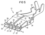
- the dome-shaped bulges 28, 29 serve defined contact points and do not touch, even if these are arranged on the lower and upper contact legs 14, 16, as can be clearly seen in FIG. 5.
- the dome-shaped bulges 28, 29 are arranged in the present exemplary embodiment between the front end of the spring contact and the point where the torn-out tabs 30 rest on the opposite contact leg, that is to say in the insertion funnel.
- the aforementioned pre-opening is essentially based on the distance between the contact legs 14, 16, which is caused by the bulges 28, 29.
- the pre-opening 19, which can be clearly seen in FIG. 2, facilitates the introduction of a mating contact into the flat spring contact 10 without loss of contact force.
- FIG. 3 On the basis of the side view of the flat spring contact 10 shown in FIG. 2 it can be seen how a stop 32 for a locking sleeve 33 shown in FIG. 3, which is pushed onto the flat spring contact 10, locks in recesses 34 provided on both sides of the housing 12.
- the locking sleeve 33 which is bent as a closed box section made of sheet metal, has its abutment line 35 Butt edges each have welding spots 36 which prevent the profile of the locking sleeve 33 from opening.
- tabs 37 for supporting the contact force of the base spring 12 are attached to the flat side of the locking sleeve 33, which contribute to reliable contacting.
- connection means 39 for a circuit board to be connected, not shown here.
- FIGS. 1 and 2 show the flat spring contact 10 according to the invention, already shown and explained in FIGS. 1 and 2, in an oblique view, from which the multi-lamella design of the contact legs 14, 16 provided with pre-opening 19 with a total of eight formed by the bulges 28, 29 Contact points are recognizable. As can be easily recognized, these are dome-shaped at the transition between the contact lamellae 20, 22, 24, 26 and the opening receiving lips 15 which adjoin at the end.
- the two tabs 30 necessary for the defined pre-opening of the insertion funnel can be seen on the lateral edges of the upper contact leg.
Landscapes
- Coupling Device And Connection With Printed Circuit (AREA)
Applications Claiming Priority (2)
| Application Number | Priority Date | Filing Date | Title |
|---|---|---|---|
| DE1996107526 DE19607526C2 (de) | 1996-02-28 | 1996-02-28 | Flachfederkontakt in Mehrlamellenausführung |
| DE19607526 | 1996-02-28 |
Publications (1)
| Publication Number | Publication Date |
|---|---|
| EP0793302A1 true EP0793302A1 (fr) | 1997-09-03 |
Family
ID=7786681
Family Applications (1)
| Application Number | Title | Priority Date | Filing Date |
|---|---|---|---|
| EP97103287A Ceased EP0793302A1 (fr) | 1996-02-28 | 1997-02-27 | Ressort de contact plat ayant plusieurs lamelles |
Country Status (2)
| Country | Link |
|---|---|
| EP (1) | EP0793302A1 (fr) |
| DE (1) | DE19607526C2 (fr) |
Cited By (1)
| Publication number | Priority date | Publication date | Assignee | Title |
|---|---|---|---|---|
| WO2016014308A1 (fr) * | 2014-07-24 | 2016-01-28 | Fci Asia Pte. Ltd | Contact d'énergie électrique |
Families Citing this family (3)
| Publication number | Priority date | Publication date | Assignee | Title |
|---|---|---|---|---|
| DE19743329A1 (de) * | 1997-09-30 | 1999-04-01 | Whitaker Corp | Elektrischer Kontakt und Steckverbinderanordnung mit einem elektrischen Kontakt und einem Gehäuse |
| DE102006062704B4 (de) * | 2006-03-01 | 2008-12-04 | Tyco Electronics Amp Gmbh | Elektrische Flachsteckhülse |
| DE102006009357B8 (de) * | 2006-03-01 | 2008-02-14 | Tyco Electronics Amp Gmbh | Elektrische Flachsteckhülse |
Citations (5)
| Publication number | Priority date | Publication date | Assignee | Title |
|---|---|---|---|---|
| FR1219360A (fr) * | 1958-12-24 | 1960-05-17 | Nouveaux contacteurs pour circuits imprimés | |
| WO1985004766A1 (fr) * | 1984-04-09 | 1985-10-24 | Amp Incorporated | Contact de douille cylindrique capable d'exercer une force de contact elevee et necessitant une faible force d'appariage |
| US5145422A (en) * | 1991-12-30 | 1992-09-08 | Molex Incorporated | Female electrical terminal with improved contact force |
| DE9202365U1 (de) * | 1992-02-24 | 1993-06-17 | Siemens Ag, 8000 Muenchen | Kontaktfeder mit Rasthülse |
| EP0656673A2 (fr) * | 1993-12-02 | 1995-06-07 | The Whitaker Corporation | Borne femelle à faible force d'insertion |
Family Cites Families (3)
| Publication number | Priority date | Publication date | Assignee | Title |
|---|---|---|---|---|
| DE8134899U1 (de) * | 1981-11-30 | 1982-04-15 | Vaudeha-Elektro GmbH, 5880 Lüdenscheid | Elektrisches Kontaktteil |
| DE8236405U1 (de) * | 1982-12-24 | 1984-10-04 | Grote & Hartmann Gmbh & Co Kg, 5600 Wuppertal | Doppelflachfederkontakt mit Überfeder |
| DE8502106U1 (de) * | 1985-01-26 | 1985-05-02 | Kabelwerke Reinshagen Gmbh, 5600 Wuppertal | Elektrischer Doppelflachfederkontakt |
-
1996
- 1996-02-28 DE DE1996107526 patent/DE19607526C2/de not_active Expired - Fee Related
-
1997
- 1997-02-27 EP EP97103287A patent/EP0793302A1/fr not_active Ceased
Patent Citations (5)
| Publication number | Priority date | Publication date | Assignee | Title |
|---|---|---|---|---|
| FR1219360A (fr) * | 1958-12-24 | 1960-05-17 | Nouveaux contacteurs pour circuits imprimés | |
| WO1985004766A1 (fr) * | 1984-04-09 | 1985-10-24 | Amp Incorporated | Contact de douille cylindrique capable d'exercer une force de contact elevee et necessitant une faible force d'appariage |
| US5145422A (en) * | 1991-12-30 | 1992-09-08 | Molex Incorporated | Female electrical terminal with improved contact force |
| DE9202365U1 (de) * | 1992-02-24 | 1993-06-17 | Siemens Ag, 8000 Muenchen | Kontaktfeder mit Rasthülse |
| EP0656673A2 (fr) * | 1993-12-02 | 1995-06-07 | The Whitaker Corporation | Borne femelle à faible force d'insertion |
Cited By (5)
| Publication number | Priority date | Publication date | Assignee | Title |
|---|---|---|---|---|
| WO2016014308A1 (fr) * | 2014-07-24 | 2016-01-28 | Fci Asia Pte. Ltd | Contact d'énergie électrique |
| CN106716727A (zh) * | 2014-07-24 | 2017-05-24 | 安费诺富加宜(亚洲)私人有限公司 | 电能触头 |
| US9905952B2 (en) | 2014-07-24 | 2018-02-27 | Fci Usa Llc | Electrical power contact |
| TWI674711B (zh) * | 2014-07-24 | 2019-10-11 | 新加坡商安姆芬諾爾富加宜(亞洲)私人有限公司 | 電源觸點 |
| CN106716727B (zh) * | 2014-07-24 | 2020-07-10 | 安费诺富加宜(亚洲)私人有限公司 | 电能触头 |
Also Published As
| Publication number | Publication date |
|---|---|
| DE19607526C2 (de) | 1998-02-26 |
| DE19607526A1 (de) | 1997-09-04 |
Similar Documents
| Publication | Publication Date | Title |
|---|---|---|
| DE1790342C3 (fr) | ||
| DE69300865T2 (de) | Elektrischer verbinder mit blech als steckkontaktmaterial. | |
| DE69702142T2 (de) | Elektrischer verbinder mit einem gehäuse und einem elektrischen kontaktelement | |
| EP3734768B1 (fr) | Connecteur enfichable d'un raccord enfichable électrique ainsi que raccord enfichable électrique ainsi formé | |
| DE1465098C3 (de) | Elektrisches Verbindungsstück | |
| EP1503457B1 (fr) | Connecteur femelle pour fiche plate | |
| DE1790275A1 (de) | Elektrische Kontakthuelse | |
| DE102016221351A1 (de) | Flachkontaktbuchse mit Ausleger | |
| CH647895A5 (de) | Elektrischer anschlussteil, verfahren zu dessen verbinden mit einem elektrischen leiter sowie verbinder mit einer mehrzahl von anschlussteilen. | |
| DE2338056B2 (de) | Elektrische Anschlußklemme | |
| EP1103088A1 (fr) | Contact de douille | |
| DE9115318U1 (de) | Elektrischer Verbinder mit reduzierter Einführkraft | |
| EP0333988A2 (fr) | Contact électrique rond miniaturisé avec douille ronde et fiche ronde | |
| EP0353330A1 (fr) | Contact à douille | |
| EP0333989A2 (fr) | Connecteur électrique | |
| DE3028809C2 (de) | Steckeranordnung zur Aufnahme eines Flachsteckers | |
| DE3214532C2 (de) | Mehrpolige Kontaktleiste | |
| WO2018141682A1 (fr) | Lame de contact pour élément de connecteur de type femelle et élément de connecteur de type femelle | |
| DE4400469C2 (de) | Elektrischer Federkontakt für Querverbinder und dergleichen | |
| DE2130729C2 (de) | Elektrischer Verbinder | |
| DE2128954B2 (de) | Elektrische Steckverbindung | |
| DE2448349C2 (de) | Verbinderanordnung mit einem mit einer gedruckten Schaltungsplatte verbundenen Verbinder | |
| DE2628090A1 (de) | Elektrisches verbindungsstueck | |
| EP0793302A1 (fr) | Ressort de contact plat ayant plusieurs lamelles | |
| EP1020954A2 (fr) | Borne de connexion électrique |
Legal Events
| Date | Code | Title | Description |
|---|---|---|---|
| PUAI | Public reference made under article 153(3) epc to a published international application that has entered the european phase |
Free format text: ORIGINAL CODE: 0009012 |
|
| AK | Designated contracting states |
Kind code of ref document: A1 Designated state(s): BE DE ES FR GB IT SE |
|
| 17P | Request for examination filed |
Effective date: 19980227 |
|
| 17Q | First examination report despatched |
Effective date: 19991203 |
|
| RAP1 | Party data changed (applicant data changed or rights of an application transferred) |
Owner name: TYCO ELECTRONICS LOGISTICS AG |
|
| GRAG | Despatch of communication of intention to grant |
Free format text: ORIGINAL CODE: EPIDOS AGRA |
|
| STAA | Information on the status of an ep patent application or granted ep patent |
Free format text: STATUS: THE APPLICATION HAS BEEN REFUSED |
|
| 18R | Application refused |
Effective date: 20010920 |