EP0793306A2 - Schirmendverbindungssystem eines Hochgeschwindigkeitskabels - Google Patents
Schirmendverbindungssystem eines Hochgeschwindigkeitskabels Download PDFInfo
- Publication number
- EP0793306A2 EP0793306A2 EP97103071A EP97103071A EP0793306A2 EP 0793306 A2 EP0793306 A2 EP 0793306A2 EP 97103071 A EP97103071 A EP 97103071A EP 97103071 A EP97103071 A EP 97103071A EP 0793306 A2 EP0793306 A2 EP 0793306A2
- Authority
- EP
- European Patent Office
- Prior art keywords
- additional
- gripping arm
- termination
- metallic shield
- metallic
- Prior art date
- Legal status (The legal status is an assumption and is not a legal conclusion. Google has not performed a legal analysis and makes no representation as to the accuracy of the status listed.)
- Ceased
Links
Images


Classifications
-
- H—ELECTRICITY
- H01—ELECTRIC ELEMENTS
- H01R—ELECTRICALLY-CONDUCTIVE CONNECTIONS; STRUCTURAL ASSOCIATIONS OF A PLURALITY OF MUTUALLY-INSULATED ELECTRICAL CONNECTING ELEMENTS; COUPLING DEVICES; CURRENT COLLECTORS
- H01R13/00—Details of coupling devices of the kinds covered by groups H01R12/70 or H01R24/00 - H01R33/00
- H01R13/648—Protective earth or shield arrangements on coupling devices, e.g. anti-static shielding
- H01R13/658—High frequency shielding arrangements, e.g. against EMI [Electro-Magnetic Interference] or EMP [Electro-Magnetic Pulse]
- H01R13/6591—Specific features or arrangements of connection of shield to conductive members
- H01R13/65912—Specific features or arrangements of connection of shield to conductive members for shielded multiconductor cable
- H01R13/65918—Specific features or arrangements of connection of shield to conductive members for shielded multiconductor cable wherein each conductor is individually surrounded by shield
-
- H—ELECTRICITY
- H01—ELECTRIC ELEMENTS
- H01R—ELECTRICALLY-CONDUCTIVE CONNECTIONS; STRUCTURAL ASSOCIATIONS OF A PLURALITY OF MUTUALLY-INSULATED ELECTRICAL CONNECTING ELEMENTS; COUPLING DEVICES; CURRENT COLLECTORS
- H01R13/00—Details of coupling devices of the kinds covered by groups H01R12/70 or H01R24/00 - H01R33/00
- H01R13/648—Protective earth or shield arrangements on coupling devices, e.g. anti-static shielding
- H01R13/658—High frequency shielding arrangements, e.g. against EMI [Electro-Magnetic Interference] or EMP [Electro-Magnetic Pulse]
- H01R13/6581—Shield structure
- H01R13/6585—Shielding material individually surrounding or interposed between mutually spaced contacts
-
- H—ELECTRICITY
- H01—ELECTRIC ELEMENTS
- H01R—ELECTRICALLY-CONDUCTIVE CONNECTIONS; STRUCTURAL ASSOCIATIONS OF A PLURALITY OF MUTUALLY-INSULATED ELECTRICAL CONNECTING ELEMENTS; COUPLING DEVICES; CURRENT COLLECTORS
- H01R13/00—Details of coupling devices of the kinds covered by groups H01R12/70 or H01R24/00 - H01R33/00
- H01R13/62—Means for facilitating engagement or disengagement of coupling parts or for holding them in engagement
- H01R13/621—Bolt, set screw or screw clamp
- H01R13/6215—Bolt, set screw or screw clamp using one or more bolts
-
- H—ELECTRICITY
- H01—ELECTRIC ELEMENTS
- H01R—ELECTRICALLY-CONDUCTIVE CONNECTIONS; STRUCTURAL ASSOCIATIONS OF A PLURALITY OF MUTUALLY-INSULATED ELECTRICAL CONNECTING ELEMENTS; COUPLING DEVICES; CURRENT COLLECTORS
- H01R13/00—Details of coupling devices of the kinds covered by groups H01R12/70 or H01R24/00 - H01R33/00
- H01R13/648—Protective earth or shield arrangements on coupling devices, e.g. anti-static shielding
- H01R13/658—High frequency shielding arrangements, e.g. against EMI [Electro-Magnetic Interference] or EMP [Electro-Magnetic Pulse]
- H01R13/6591—Specific features or arrangements of connection of shield to conductive members
- H01R13/6592—Specific features or arrangements of connection of shield to conductive members the conductive member being a shielded cable
-
- H—ELECTRICITY
- H01—ELECTRIC ELEMENTS
- H01R—ELECTRICALLY-CONDUCTIVE CONNECTIONS; STRUCTURAL ASSOCIATIONS OF A PLURALITY OF MUTUALLY-INSULATED ELECTRICAL CONNECTING ELEMENTS; COUPLING DEVICES; CURRENT COLLECTORS
- H01R4/00—Electrically-conductive connections between two or more conductive members in direct contact, i.e. touching one another; Means for effecting or maintaining such contact; Electrically-conductive connections having two or more spaced connecting locations for conductors and using contact members penetrating insulation
- H01R4/02—Soldered or welded connections
- H01R4/027—Soldered or welded connections comprising means for positioning or holding the parts to be soldered or welded
-
- H—ELECTRICITY
- H01—ELECTRIC ELEMENTS
- H01R—ELECTRICALLY-CONDUCTIVE CONNECTIONS; STRUCTURAL ASSOCIATIONS OF A PLURALITY OF MUTUALLY-INSULATED ELECTRICAL CONNECTING ELEMENTS; COUPLING DEVICES; CURRENT COLLECTORS
- H01R9/00—Structural associations of a plurality of mutually-insulated electrical connecting elements, e.g. terminal strips or terminal blocks; Terminals or binding posts mounted upon a base or in a case; Bases therefor
- H01R9/03—Connectors arranged to contact a plurality of the conductors of a multiconductor cable, e.g. tapping connections
- H01R9/05—Connectors arranged to contact a plurality of the conductors of a multiconductor cable, e.g. tapping connections for coaxial cables
- H01R9/0518—Connection to outer conductor by crimping or by crimping ferrule
Definitions
- This invention generally relates to the art of electrical connectors and, particularly, to a system for terminating the metallic shield of a high speed cable, such as the metallic braid of the cable.
- a typical high speed cable includes a center conductor or core surrounded by a tube-like inner dielectric.
- a shield is disposed outside the inner dielectric for shielding and/or grounding the cable.
- the shield typically is a tubular metallic braid.
- one or more longitudinal conductive wires have also been used and are commonly called “drain wires.”
- An insulating jacket surrounds the composite cable outside the shield.
- the connectors typically have contacts which are terminated to the center conductor or core of the cable.
- the connectors also have one form or another of a terminating member for terminating the metallic shield of the high speed cable, usually for grounding purposes.
- a typical system in such connectors terminates the metallic shield to the terminating member by soldering.
- Other systems use crimping procedures to crimp at least a portion of the terminating member securely to the metallic braid for commoning purposes.
- the outside diameter of a small coaxial cable may be on the order of 0.090 inch.
- the outside diameter of the inner dielectric surrounding the conductor/core may be on the order of 0.051 inch, and the diameter of the center conductor/core may be on the order 0.012 inch.
- Coaxial cables having even smaller dimensional parameters have been used.
- the problems in terminating such very small coaxial cables often revolve around terminating the metallic shield of the cable. For instance, if soldering methods are used, applying heat (necessary for soldering) in direct proximity to the metallic shield can cause heat damage to the underlying inner dielectric and, in fact, substantially disintegrate or degrade the inner dielectric. If conventional crimp-type terminations are used, typical crimping forces often will crush or deform the inner dielectric surrounding the center conductor/core of the cable.
- this transition zone be held to as small an area as possible and as short a length (i.e., longitudinally of the cable) as possible.
- the metallic shield or braid should be terminated over an area (or at least at two points) approximately 1800 apart in relation to the center conductor/core of the cable.
- the flat terminating member should overlap or at least extend to the point where the metallic shield or braid is separated from its tubular configuration surrounding the conductor/core of the cable. Still further, it is desirable that the metallic shield or braid of any given high speed cable be terminated on the same side of the flat terminating member as the center conductor/core of the cable.
- the present invention is directed to solving the above-identified problems and satisfying as many of the above-identified design parameters as possible in an improved system for terminating the metallic shield of a high speed cable to a terminating member, such as a ground plate.
- An object, therefore, of the invention is to provide a new and improved system or terminal for terminating the metallic shields of a plurality of high speed cables.
- a terminal for terminating the shields of a plurality of high speed cables each having an outer jacket and an inner metallic shield with a portion of the outer jacket removed to expose a portion of the metallic shield.
- the terminal includes a conductive ground plate portion.
- a gripping arm projects from the ground plate portion for embracing the plurality of high speed cables in direct engagement with the exposed portions of the metallic shields thereof.
- a solder connection is disposed between the gripping arm and the metallic shields.
- the ground plate is generally planar, and the gripping arm projects inwardly from an edge of the ground plate.
- a pair of the gripping arms project from opposite sides of the ground plate, with the gripping arms projecting inwardly from opposite edges of the ground plate.
- each gripping arm is contoured to cooperate with the ground plate to define discrete chambers for respectively receiving the plurality of high speed cables.
- each gripping arm is undulated to define generally semi-cylindrical portions for respectively embracing the plurality of high speed cables.
- each gripping arm includes an opening for receiving the solder connection therethrough.
- the opening is a circumferentially extending slot.
- the slot is on the order of 0.040 inch wide.
- the solder connection is disposed on the inside of the gripping arms by solder material having been deposited thereat and subsequently reflowed.
- the solder material is deposited as an inlay on the inside of the gripping arms.
- a shielded electrical connector which is a hybrid electrical connector for terminating both the conductors of slower data transmission lines and the conductors of high speed or high frequency transmission lines.
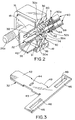
- electrical connector 10 includes a dielectric housing 12 (Fig. 2) mounting a plurality of data transmission terminals 14 (Fig. 1).
- a conductive shield, generally designated 16, substantially surrounds dielectric housing 12 and has a shroud portion 18 projecting forwardly about the mating ends of data transmission terminals 14.
- a two-piece backshell (not shown) substantially in conformance with that shown in U.S. Patent No. 5,358,428, dated October 25, 1994, projects rearwardly of housing 12 and shield 16.
- An overmolded boot 20 includes an integral cable strain-relief 22 that is in engagement with a composite electrical cable 24 which includes both the data transmission lines and the high speed or high frequency transmission lines.
- a pair of thumb screws 26 project through the overmolded boot and include externally threaded forward distal ends 26a for securing the connector to a complementary mating connector, panel or other structure.
- a high speed signal transmission terminal module is inserted into a passage 31 in dielectric housing 12 from the rear thereof.
- the terminal module includes a pair of identical terminal blocks 30a and 30b which clamp a ground plate, generally designated 32, therebetween.
- Each terminal block includes a post 34 and a recess. The post from each terminal block extends from each terminal block through a hole or slot 44 (Fig. 3) in the ground plate and into a recess in the other terminal block to secure terminal blocks 30a and 30b to ground plate 32 as a subassembly. Once this subassembly is inserted into passage 31 in housing 12 as shown in Figure 2, the terminal blocks are effective to clamp the ground plate therebetween.
- the terminal module is held within the dielectric housing by ramped latches 36 on each terminal block.
- Each terminal block 30a and 30b is overmolded about at least one high speed signal terminal 38.
- the contact ends of a pair of the terminals 38, along with the forward end of ground plate 32, are shown projecting forwardly of the connector in Figure 1, within the surrounding shroud portion 18 of shield 16.
- the rear ends 38a of terminals 38 (Fig. 7) are terminated to the center conductor/cores 60 of a plurality of coaxial cables, generally designated 40 in Figure 2.
- the invention is particularly directed to the manner of termination of the metallic shields of the coaxial cables to ground plate 32, as described below.
- Figure 3 shows a blank, generally designated “B,” stamped from conductive sheet metal material and from which ground plate 32 is formed.
- Blank “B” is generally T-shaped and includes a leg or stem portion 42 which will form a blade portion for ground plate 32.
- the blade portion includes aperture 44 through which posts 34 (Fig. 2) of terminal blocks 30a and 30b extend.
- a wing or arm 46 projects outwardly at one end of leg 42 generally at each opposite edge thereof. These wings will form the gripping arms of the ground plate, as will be seen hereinafter.
- Each wing or gripping arm has an elongated slot 48 to facilitate the solder termination described hereinafter.
- soldering iron When soldering cable shields 56 to ground plate 32, it is desirable to use a soldering iron having a relatively small tip. Although it is desirable to dimension the slot wide enough to facilitate adequate solder flow throughout the slot, it should be narrow enough to prevent the relatively small tip of the soldering iron from contacting the braid or shield 56 of the cable, which could result in damage to the underlying inner dielectric 62.
- Each slot is on the order of approximately 0.040 inch wide, although it is believed that such slot could be within the range of 0.010 to 0.110 inch wide.
- barbs or teeth 49 are stamped at the opposite edges of blade portion 42 to facilitate holding the subassembly of the ground plate and terminal blocks 30a and 30b within the housing.
- ground plate 32 is provided with a positioning and gripping arm on each side of the ground plate for positioning and gripping a pair of coaxial cables.
- the arms are located at the extreme rear distal end of blade portion 42.
- the ground plate can terminate from one to four coaxial cables depending on the specifications of the connector. In some computer applications, three cables may be used to carry the red, green and blue chroma signals for a monitor. A fourth cable might be used for flat screen monitors for carrying the pixel clock timing signals.
- FIG 4 shows the stamped blank "B" of Figure 3 with wings 46 having been bent inwardly to form an upper positioning and gripping arm, generally designated 50a, and a lower positioning and gripping arm, generally designated 50b.
- Each gripping arm is contoured in an undulated configuration to define a pair of semi-cylindrical portions 52 which cooperate with blade portion 42 to define discrete chambers 54 for receiving a plurality of coaxial cables, as described hereinafter.
- slots 48 in the arms extend in a circumferential direction about portions of each chamber 54.
- each gripping arm extends entirely across blade portion 42, leaving only a very small gap 56 between the distal end of the arm and the blade portion. Therefore, the coaxial cables are substantially entirely surrounded by the gripping arms and the blade portions.
- the ground plate can terminate from one to four coaxial cables depending on the specifications of the connector.
- FIG. 5 shows the formed ground plate 32 of Figure 4 with a pair of coaxial cables 40 positioned within chambers 54 of upper gripping arm 50a.
- each coaxial cable 40 is of a conventional construction in that each cable includes a center conductor or core 60 surrounded by a tube-like inner dielectric 62.
- a metallic shield in the form of a tubular metallic braid 64 surrounds inner dielectric 62.
- An insulating jacket 66 as of plastic or the like, surrounds metallic braid 64 to form the overall composite coaxial cable 40.
- Figure 5 also shows that center conductor/core 60 of each coaxial cable 40 has been stripped to expose a given length thereof which will be soldered to the inner end of one of the high speed signal transmission terminals 38 (Fig. 7).
- the outer insulating jacket 66 of each cable also has been cut-back to expose a given length of the respective metallic shield 64. Therefore, the exposed shields can be soldered to the gripping arms 50a or 50b of ground plate 32 as discussed below.
- Figure 5 shows gripping arms 50a and 50b in position for receiving coaxial cables 40 prepared as described above.
- Figure 5 shows two coaxial cables 40 positioned within upper gripping arm 50a longitudinally so that metallic shields 64 of the cables are in registry with the gripping arm on the inside thereof.
- Each coaxial cable is positioned longitudinally within one of the chambers 54 defined by semi-cylindrical portions 52.
- the coaxial cables may be positioned within the gripping arm by a slight press-fit.
- the gripping arms may be initially formed to freely receive the coaxial cables longitudinally thereinto, whereas the arms initially function only to position the cables, and, thereafter, the arms may be further formed to positively grip the coaxial cables and completely close gaps 56.
- the free end of gripping arms 50a and 50b could include some type of latch (not shown) to engage or overlap a portion of ground plate 32 or the other gripping arm in order to completely encircle the coaxial cable.
- some type of latch (not shown) to engage or overlap a portion of ground plate 32 or the other gripping arm in order to completely encircle the coaxial cable.
- the gripping arms are not crimped onto the metallic shields as is typical in the crimping art. Rather, an amount of force is used to slightly form the gripping arms inwardly, so as only to grip and retain the coaxial cables prior to soldering.
- the gripping or crimping pressure should not be excessive so as to damage the underlying inner dielectric material 62 to any extent, which could affect the electrical performance thereof.
- Ground plate 32 then is mechanically and electrically connected to metallic shields 64 of the coaxial cables by soldering the metallic shields to gripping arm 50a by applying solder through slot 48 in the gripping arm, as at "S" in Figure 5.
- the slots are formed on the order of approximately 0.040 inch wide to prevent the application of concentrated heat directly to the metallic shield, which could cause heat damage to the underlying inner dielectric.
- the slot should be sufficiently narrow to at least prevent whatever soldering iron or tool is used from passing through the slot and into direct engagement with the metallic shield. Such engagement may result in damage to the underlying inner dielectric.
- the slots restrict the amount of soldering heat which is transmitted inwardly to the inner dielectric.
- the slots extend in a circumferential direction to provide a large circumferential area of access to the metallic shields in a circumferential direction.
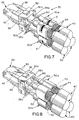
- ground plate 32 is inverted as shown in Figure 6 and another pair of coaxial cables are inserted into chambers 54 of the other gripping arm 50b and soldered thereto as described above in relation to Figure 5.
- terminal blocks 30a and 30b including high speed signal transmission terminals 38 are then assembled to terminal blocks 30a and 30b including high speed signal transmission terminals 38 to form terminal module 30 as shown in Figure 7 and described above in relation to Figure 2.
- Center conductors/cores 60 of the coaxial cables are then connected, as by soldering, welding or otherwise securing to the inner ends 38a of terminals 38, while terminal blocks 30a and 30b clamp blade portion 42 of ground plate 32 therebetween, as shown in Figure 2 and described above.
- the terminal module then is mounted within dielectric housing 12 as shown in Figure 2. If desired, terminal blocks 30a and 30b could be mounted to blade portion 42 of ground plate 32 prior to inserting cables 40 into gripping arms 50a and 50b. In other words, the ground plate would have the terminal blocks mounted thereon at the beginning of the termination process.
- Figure 8 shows an alternative embodiment of the invention wherein slots 48 have been eliminated and solder material is deposited or inlayed on the inside of gripping arms 50a and 50b as indicated by dotted lines 70 and subsequently reflowed during the soldering process.
- the inlayed solder material is not visible from the outside of the structure.
- the inlayed solder material is heated and reflowed to mechanically and electrically connect the gripping arms to the metallic shields of the coaxial cables.
Landscapes
- Details Of Connecting Devices For Male And Female Coupling (AREA)
- Coupling Device And Connection With Printed Circuit (AREA)
- Multi-Conductor Connections (AREA)
- Cable Accessories (AREA)
- Manufacturing Of Electrical Connectors (AREA)
Applications Claiming Priority (2)
| Application Number | Priority Date | Filing Date | Title |
|---|---|---|---|
| US60930796A | 1996-03-01 | 1996-03-01 | |
| US609307 | 1996-03-01 |
Publications (2)
| Publication Number | Publication Date |
|---|---|
| EP0793306A2 true EP0793306A2 (de) | 1997-09-03 |
| EP0793306A3 EP0793306A3 (de) | 1998-11-25 |
Family
ID=24440232
Family Applications (1)
| Application Number | Title | Priority Date | Filing Date |
|---|---|---|---|
| EP97103071A Ceased EP0793306A3 (de) | 1996-03-01 | 1997-02-26 | Schirmendverbindungssystem eines Hochgeschwindigkeitskabels |
Country Status (7)
| Country | Link |
|---|---|
| US (1) | US5823825A (de) |
| EP (1) | EP0793306A3 (de) |
| JP (1) | JP3015942B2 (de) |
| KR (1) | KR100282631B1 (de) |
| CN (1) | CN1091963C (de) |
| MY (1) | MY129778A (de) |
| TW (1) | TW326584B (de) |
Cited By (1)
| Publication number | Priority date | Publication date | Assignee | Title |
|---|---|---|---|---|
| EP1432095A3 (de) * | 2002-12-17 | 2005-07-20 | Franz Knorr | Anschlussvorrichtung für Kabel bzw. Leitungen |
Families Citing this family (38)
| Publication number | Priority date | Publication date | Assignee | Title |
|---|---|---|---|---|
| US5961348A (en) * | 1996-03-01 | 1999-10-05 | Molex Incorporated | System for terminating the shield of a high speed cable |
| GB9712457D0 (en) * | 1997-06-17 | 1997-08-20 | Smiths Industries Plc | Electrical connection |
| JPH11219758A (ja) * | 1998-01-30 | 1999-08-10 | Yazaki Corp | 多極シールドコネクタ及び相手シールドコネクタ |
| US6059607A (en) * | 1998-03-17 | 2000-05-09 | Molex Incorporated | Shielded electrical connector |
| JP3435073B2 (ja) * | 1998-08-25 | 2003-08-11 | 矢崎総業株式会社 | シールド電線の接合構造及び接合方法 |
| GB9821511D0 (en) * | 1998-10-03 | 1998-11-25 | Smiths Industries Plc | Electrical connection |
| US6186828B1 (en) * | 1999-08-30 | 2001-02-13 | Molex Incorporated | Electrical connector including coaxial cable management system |
| US6857899B2 (en) | 1999-10-08 | 2005-02-22 | Tensolite Company | Cable structure with improved grounding termination in the connector |
| US6217372B1 (en) | 1999-10-08 | 2001-04-17 | Tensolite Company | Cable structure with improved grounding termination in the connector |
| FR2805932A1 (fr) * | 2000-03-02 | 2001-09-07 | Fci France | Module blinde de connexion et procede de realisation d'un connecteur blinde |
| JP3656187B2 (ja) * | 2000-04-17 | 2005-06-08 | 日本航空電子工業株式会社 | シールドケーブル用コネクタ |
| US6428344B1 (en) * | 2000-07-31 | 2002-08-06 | Tensolite Company | Cable structure with improved termination connector |
| GB2373106B (en) * | 2001-03-08 | 2004-06-16 | Smiths Group Plc | Electricl connection and connectors |
| US6722898B2 (en) | 2001-10-17 | 2004-04-20 | Molex Incorporated | Connector with improved grounding means |
| US6726503B2 (en) | 2002-06-21 | 2004-04-27 | Molex Incorporated | Electrical connector with wire management module |
| TWI246236B (en) * | 2002-07-22 | 2005-12-21 | Rapid Conn Inc | Electronic connector for a cable |
| US6786763B2 (en) * | 2003-01-28 | 2004-09-07 | Hon Hai Precision Ind. Co., Ltd. | Cable end connector assembly having relatively simple structure and improved terminal structure |
| DE10352325B4 (de) * | 2003-11-06 | 2013-11-07 | Bayerische Motoren Werke Aktiengesellschaft | Verfahren zum Herstellen einer elektrisch leitenden Verbindung u. Kontaktteil mit einer derart hergestellten elektrischen Verbindung |
| TWM253972U (en) * | 2004-03-16 | 2004-12-21 | Comax Technology Inc | Electric connector with grounding effect |
| DE102006013490A1 (de) * | 2005-03-23 | 2006-10-05 | Yazaki Corp. | Struktur zur Koaxialkabelenden-Verarbeitung, Koaxialkabel-Abschirmungsklemme und Press-Befestigungsvorrichtung |
| CN100561804C (zh) * | 2006-01-20 | 2009-11-18 | 西门子(中国)有限公司 | 电信号连接器 |
| US7306479B1 (en) * | 2006-07-05 | 2007-12-11 | Hon Hai Precision Ind. Co., Ltd. | Cable connector assembly with strain relief member |
| CN201178210Y (zh) * | 2008-02-01 | 2009-01-07 | 富士康(昆山)电脑接插件有限公司 | 线缆连接器 |
| US9791634B2 (en) | 2008-09-30 | 2017-10-17 | Apple Inc. | Magnetic connector with optical signal path |
| US7841776B2 (en) | 2008-09-30 | 2010-11-30 | Apple Inc. | Magnetic connector with optical signal path |
| EP2369682A4 (de) * | 2008-12-16 | 2014-10-01 | Fujikura Ltd | Verbindungsstruktur eines koaxialkabelbaums |
| JP5589778B2 (ja) * | 2010-11-05 | 2014-09-17 | 日立金属株式会社 | 差動信号伝送用ケーブルと回路基板の接続構造及び接続方法 |
| US8911254B2 (en) * | 2011-06-03 | 2014-12-16 | Ppc Broadband, Inc. | Multi-conductor cable connector having more than one coaxial cable and method thereof |
| DE102011052792B4 (de) * | 2011-08-18 | 2014-05-22 | HARTING Electronics GmbH | Isolierkörper mit Schirmkreuz |
| JP2013225475A (ja) * | 2012-03-19 | 2013-10-31 | Fujitsu Component Ltd | コンタクト、コネクタ、及びその製造方法 |
| DE102012022004B3 (de) | 2012-11-12 | 2014-02-06 | HARTING Electronics GmbH | Isolierkörper mit Schirmkreuz |
| DE102014214416A1 (de) * | 2014-07-23 | 2016-01-28 | Robert Bosch Gmbh | Elektrische Verbindungsanordnung |
| JP6615447B2 (ja) * | 2014-10-16 | 2019-12-04 | 宏致電子股▲ふん▼有限公司 | 電気コネクタ |
| CN108063326B (zh) * | 2016-11-07 | 2020-01-14 | 泰科电子(上海)有限公司 | 线夹和线缆组件 |
| JP6579398B2 (ja) * | 2017-09-19 | 2019-09-25 | Smk株式会社 | シールドコネクタ及びその接続方法 |
| JP7398954B2 (ja) * | 2019-12-26 | 2023-12-15 | 株式会社クボタ | 作業機 |
| CN112563829B (zh) * | 2020-11-17 | 2025-08-05 | 深圳市得润电子股份有限公司 | 电连接器和电子产品 |
| CN113630915B (zh) * | 2021-07-29 | 2024-11-22 | 上海师范大学 | 灵活定制高可调柔性微加热器的复合加工方法及微加热器 |
Family Cites Families (18)
| Publication number | Priority date | Publication date | Assignee | Title |
|---|---|---|---|---|
| US2640185A (en) * | 1950-11-25 | 1953-05-26 | Alden Milton | Resilient solder terminal |
| DE1002435B (de) * | 1954-04-07 | 1957-02-14 | Siemens Ag | Auf elektrische Anschlussfahnen aufsteckbare Klammer fuer isolierte Leiter |
| US4615578A (en) * | 1984-12-05 | 1986-10-07 | Raychem Corporation | Mass termination device and connection assembly |
| CA1279912C (en) * | 1986-10-15 | 1991-02-05 | Toshiaki Tokizane | High-frequency cable connector |
| JP2511123B2 (ja) * | 1988-10-13 | 1996-06-26 | 矢崎総業株式会社 | 圧着端子、及び圧着端子と電線の接続方法 |
| US4993968A (en) * | 1989-03-02 | 1991-02-19 | Precision Interconnect Corporation | Economical connector system for an array of conductors |
| JPH0734373B2 (ja) * | 1989-11-15 | 1995-04-12 | ヒロセ電機株式会社 | コネクタ |
| US5197893A (en) * | 1990-03-14 | 1993-03-30 | Burndy Corporation | Connector assembly for printed circuit boards |
| US5061827A (en) * | 1990-06-27 | 1991-10-29 | Amp Incorporated | Termination of a small coaxial cable |
| JPH0737261Y2 (ja) * | 1990-08-30 | 1995-08-23 | ヒロセ電機株式会社 | 電気コネクタ |
| JPH0452368U (de) * | 1990-09-10 | 1992-05-01 | ||
| JPH0452370U (de) * | 1990-09-10 | 1992-05-01 | ||
| JPH0722054Y2 (ja) * | 1990-09-11 | 1995-05-17 | ヒロセ電機株式会社 | 電気コネクタ |
| US5190473A (en) * | 1992-05-18 | 1993-03-02 | Amp Incorporated | Microcoaxial cable connector |
| JP3415889B2 (ja) * | 1992-08-18 | 2003-06-09 | ザ ウィタカー コーポレーション | シールドコネクタ |
| US5304069A (en) | 1993-07-22 | 1994-04-19 | Molex Incorporated | Grounding electrical connectors |
| FR2718299B1 (fr) * | 1994-03-30 | 1996-05-31 | Telemecanique | Prise de masse sur blindage de câble électrique. |
| US5509827A (en) * | 1994-11-21 | 1996-04-23 | Cray Computer Corporation | High density, high bandwidth, coaxial cable, flexible circuit and circuit board connection assembly |
-
1997
- 1997-02-21 TW TW086102095A patent/TW326584B/zh active
- 1997-02-24 JP JP9081795A patent/JP3015942B2/ja not_active Expired - Fee Related
- 1997-02-26 EP EP97103071A patent/EP0793306A3/de not_active Ceased
- 1997-02-27 MY MYPI97000767A patent/MY129778A/en unknown
- 1997-02-28 KR KR1019970006838A patent/KR100282631B1/ko not_active Expired - Fee Related
- 1997-02-28 CN CN97110293A patent/CN1091963C/zh not_active Expired - Fee Related
- 1997-10-06 US US08/944,718 patent/US5823825A/en not_active Expired - Fee Related
Cited By (1)
| Publication number | Priority date | Publication date | Assignee | Title |
|---|---|---|---|---|
| EP1432095A3 (de) * | 2002-12-17 | 2005-07-20 | Franz Knorr | Anschlussvorrichtung für Kabel bzw. Leitungen |
Also Published As
| Publication number | Publication date |
|---|---|
| JPH1032052A (ja) | 1998-02-03 |
| JP3015942B2 (ja) | 2000-03-06 |
| TW326584B (en) | 1998-02-11 |
| MX9701559A (es) | 1997-09-30 |
| KR100282631B1 (ko) | 2001-02-15 |
| CN1091963C (zh) | 2002-10-02 |
| MY129778A (en) | 2007-04-30 |
| KR970068033A (ko) | 1997-10-13 |
| EP0793306A3 (de) | 1998-11-25 |
| CN1170257A (zh) | 1998-01-14 |
| US5823825A (en) | 1998-10-20 |
Similar Documents
| Publication | Publication Date | Title |
|---|---|---|
| US5823825A (en) | System for terminating the shield of a high speed cable | |
| US5718607A (en) | System for terminating the shield of a high speed cable | |
| US5725387A (en) | System for terminating the shield of a high speed cable | |
| US5716236A (en) | System for terminating the shield of a high speed cable | |
| US5711686A (en) | System for terminating the shield of a high speed cable | |
| US5961348A (en) | System for terminating the shield of a high speed cable | |
| US5785555A (en) | System for terminating the shield of a high speed cable | |
| US4634208A (en) | Electrical plug connector and method of terminating a cable therewith | |
| US5768771A (en) | System for terminating the shield of a high speed cable | |
| EP1436863A1 (de) | Verbinder mit verbesserter erdung | |
| MXPA97001560A (en) | System to complete the protection of a cable dealta veloci | |
| US6364701B1 (en) | System for terminating the shield of a high speed cable | |
| EP0542075B1 (de) | Verfahren zum Anschliessen eines elektrischen koaxialen Miniatursteckers und sich daraus ergebender Steckeranschluss | |
| MXPA97001563A (en) | System to complete the shield of a high speed cable | |
| MXPA97001565A (en) | System to complete the shield of a cable aalta veloci |
Legal Events
| Date | Code | Title | Description |
|---|---|---|---|
| PUAI | Public reference made under article 153(3) epc to a published international application that has entered the european phase |
Free format text: ORIGINAL CODE: 0009012 |
|
| AK | Designated contracting states |
Kind code of ref document: A2 Designated state(s): DE FR GB IT NL |
|
| PUAL | Search report despatched |
Free format text: ORIGINAL CODE: 0009013 |
|
| AK | Designated contracting states |
Kind code of ref document: A3 Designated state(s): DE FR GB IT NL |
|
| 17P | Request for examination filed |
Effective date: 19990429 |
|
| 17Q | First examination report despatched |
Effective date: 20001019 |
|
| RTI1 | Title (correction) |
Free format text: SYSTEM FOR TERMINATING THE SHIELD OF A PAIR OF HIGH SPEED CABLE |
|
| GRAG | Despatch of communication of intention to grant |
Free format text: ORIGINAL CODE: EPIDOS AGRA |
|
| STAA | Information on the status of an ep patent application or granted ep patent |
Free format text: STATUS: THE APPLICATION HAS BEEN REFUSED |
|
| 18R | Application refused |
Effective date: 20020513 |