EP0793307A2 - Système de terminaison d'écran d'un câble à grande vitesse - Google Patents
Système de terminaison d'écran d'un câble à grande vitesse Download PDFInfo
- Publication number
- EP0793307A2 EP0793307A2 EP97103080A EP97103080A EP0793307A2 EP 0793307 A2 EP0793307 A2 EP 0793307A2 EP 97103080 A EP97103080 A EP 97103080A EP 97103080 A EP97103080 A EP 97103080A EP 0793307 A2 EP0793307 A2 EP 0793307A2
- Authority
- EP
- European Patent Office
- Prior art keywords
- additional
- metallic shield
- gripping arms
- gripping
- metallic
- Prior art date
- Legal status (The legal status is an assumption and is not a legal conclusion. Google has not performed a legal analysis and makes no representation as to the accuracy of the status listed.)
- Ceased
Links
- 238000000034 method Methods 0.000 claims abstract description 26
- 238000005476 soldering Methods 0.000 claims abstract description 23
- 239000004020 conductor Substances 0.000 claims description 37
- 229910000679 solder Inorganic materials 0.000 claims description 13
- 230000013011 mating Effects 0.000 claims description 6
- 239000003989 dielectric material Substances 0.000 claims description 4
- 239000002184 metal Substances 0.000 claims description 3
- 229910052751 metal Inorganic materials 0.000 claims description 3
- XEEYBQQBJWHFJM-UHFFFAOYSA-N Iron Chemical compound [Fe] XEEYBQQBJWHFJM-UHFFFAOYSA-N 0.000 description 8
- 230000005540 biological transmission Effects 0.000 description 6
- 229910052742 iron Inorganic materials 0.000 description 4
- 230000008054 signal transmission Effects 0.000 description 4
- 239000002131 composite material Substances 0.000 description 3
- 238000002788 crimping Methods 0.000 description 3
- 239000000463 material Substances 0.000 description 2
- 239000007769 metal material Substances 0.000 description 2
- 230000007704 transition Effects 0.000 description 2
- ATJFFYVFTNAWJD-UHFFFAOYSA-N Tin Chemical compound [Sn] ATJFFYVFTNAWJD-UHFFFAOYSA-N 0.000 description 1
- 229910010293 ceramic material Inorganic materials 0.000 description 1
- 239000011248 coating agent Substances 0.000 description 1
- 238000000576 coating method Methods 0.000 description 1
- 230000000295 complement effect Effects 0.000 description 1
- 238000004883 computer application Methods 0.000 description 1
- 238000010276 construction Methods 0.000 description 1
- 239000011810 insulating material Substances 0.000 description 1
- 238000009413 insulation Methods 0.000 description 1
- 210000003813 thumb Anatomy 0.000 description 1
- 238000003466 welding Methods 0.000 description 1
Images


Classifications
-
- H—ELECTRICITY
- H01—ELECTRIC ELEMENTS
- H01R—ELECTRICALLY-CONDUCTIVE CONNECTIONS; STRUCTURAL ASSOCIATIONS OF A PLURALITY OF MUTUALLY-INSULATED ELECTRICAL CONNECTING ELEMENTS; COUPLING DEVICES; CURRENT COLLECTORS
- H01R13/00—Details of coupling devices of the kinds covered by groups H01R12/70 or H01R24/00 - H01R33/00
- H01R13/648—Protective earth or shield arrangements on coupling devices, e.g. anti-static shielding
- H01R13/658—High frequency shielding arrangements, e.g. against EMI [Electro-Magnetic Interference] or EMP [Electro-Magnetic Pulse]
- H01R13/6591—Specific features or arrangements of connection of shield to conductive members
- H01R13/65912—Specific features or arrangements of connection of shield to conductive members for shielded multiconductor cable
- H01R13/65918—Specific features or arrangements of connection of shield to conductive members for shielded multiconductor cable wherein each conductor is individually surrounded by shield
-
- H—ELECTRICITY
- H01—ELECTRIC ELEMENTS
- H01R—ELECTRICALLY-CONDUCTIVE CONNECTIONS; STRUCTURAL ASSOCIATIONS OF A PLURALITY OF MUTUALLY-INSULATED ELECTRICAL CONNECTING ELEMENTS; COUPLING DEVICES; CURRENT COLLECTORS
- H01R13/00—Details of coupling devices of the kinds covered by groups H01R12/70 or H01R24/00 - H01R33/00
- H01R13/648—Protective earth or shield arrangements on coupling devices, e.g. anti-static shielding
- H01R13/658—High frequency shielding arrangements, e.g. against EMI [Electro-Magnetic Interference] or EMP [Electro-Magnetic Pulse]
- H01R13/6581—Shield structure
- H01R13/6585—Shielding material individually surrounding or interposed between mutually spaced contacts
-
- H—ELECTRICITY
- H01—ELECTRIC ELEMENTS
- H01R—ELECTRICALLY-CONDUCTIVE CONNECTIONS; STRUCTURAL ASSOCIATIONS OF A PLURALITY OF MUTUALLY-INSULATED ELECTRICAL CONNECTING ELEMENTS; COUPLING DEVICES; CURRENT COLLECTORS
- H01R13/00—Details of coupling devices of the kinds covered by groups H01R12/70 or H01R24/00 - H01R33/00
- H01R13/62—Means for facilitating engagement or disengagement of coupling parts or for holding them in engagement
- H01R13/621—Bolt, set screw or screw clamp
- H01R13/6215—Bolt, set screw or screw clamp using one or more bolts
-
- H—ELECTRICITY
- H01—ELECTRIC ELEMENTS
- H01R—ELECTRICALLY-CONDUCTIVE CONNECTIONS; STRUCTURAL ASSOCIATIONS OF A PLURALITY OF MUTUALLY-INSULATED ELECTRICAL CONNECTING ELEMENTS; COUPLING DEVICES; CURRENT COLLECTORS
- H01R13/00—Details of coupling devices of the kinds covered by groups H01R12/70 or H01R24/00 - H01R33/00
- H01R13/648—Protective earth or shield arrangements on coupling devices, e.g. anti-static shielding
- H01R13/658—High frequency shielding arrangements, e.g. against EMI [Electro-Magnetic Interference] or EMP [Electro-Magnetic Pulse]
- H01R13/6591—Specific features or arrangements of connection of shield to conductive members
- H01R13/6592—Specific features or arrangements of connection of shield to conductive members the conductive member being a shielded cable
-
- H—ELECTRICITY
- H01—ELECTRIC ELEMENTS
- H01R—ELECTRICALLY-CONDUCTIVE CONNECTIONS; STRUCTURAL ASSOCIATIONS OF A PLURALITY OF MUTUALLY-INSULATED ELECTRICAL CONNECTING ELEMENTS; COUPLING DEVICES; CURRENT COLLECTORS
- H01R4/00—Electrically-conductive connections between two or more conductive members in direct contact, i.e. touching one another; Means for effecting or maintaining such contact; Electrically-conductive connections having two or more spaced connecting locations for conductors and using contact members penetrating insulation
- H01R4/10—Electrically-conductive connections between two or more conductive members in direct contact, i.e. touching one another; Means for effecting or maintaining such contact; Electrically-conductive connections having two or more spaced connecting locations for conductors and using contact members penetrating insulation effected solely by twisting, wrapping, bending, crimping, or other permanent deformation
- H01R4/18—Electrically-conductive connections between two or more conductive members in direct contact, i.e. touching one another; Means for effecting or maintaining such contact; Electrically-conductive connections having two or more spaced connecting locations for conductors and using contact members penetrating insulation effected solely by twisting, wrapping, bending, crimping, or other permanent deformation by crimping
- H01R4/187—Electrically-conductive connections between two or more conductive members in direct contact, i.e. touching one another; Means for effecting or maintaining such contact; Electrically-conductive connections having two or more spaced connecting locations for conductors and using contact members penetrating insulation effected solely by twisting, wrapping, bending, crimping, or other permanent deformation by crimping combined with soldering or welding
-
- H—ELECTRICITY
- H01—ELECTRIC ELEMENTS
- H01R—ELECTRICALLY-CONDUCTIVE CONNECTIONS; STRUCTURAL ASSOCIATIONS OF A PLURALITY OF MUTUALLY-INSULATED ELECTRICAL CONNECTING ELEMENTS; COUPLING DEVICES; CURRENT COLLECTORS
- H01R9/00—Structural associations of a plurality of mutually-insulated electrical connecting elements, e.g. terminal strips or terminal blocks; Terminals or binding posts mounted upon a base or in a case; Bases therefor
- H01R9/03—Connectors arranged to contact a plurality of the conductors of a multiconductor cable, e.g. tapping connections
- H01R9/05—Connectors arranged to contact a plurality of the conductors of a multiconductor cable, e.g. tapping connections for coaxial cables
- H01R9/0518—Connection to outer conductor by crimping or by crimping ferrule
Definitions
- This invention generally relates to the art of electrical connectors and, particularly, to a system for terminating the metallic shield of a high speed cable, such as the metallic braid of the cable.
- a typical high speed cable includes a center conductor or core surrounded by a tube-like inner dielectric.
- a shield is disposed outside the inner dielectric for shielding and/or grounding the cable.
- the shield typically is a tubular metallic braid.
- one or more longitudinal conductive wires have also been used and are commonly called “drain wires.”
- An insulating jacket surrounds the composite cable outside the shield.
- the connectors typically have contacts which are terminated to the center conductor or core of the cable.
- the connectors also have one form or another of a terminating member for terminating the metallic shield of the high speed cable, usually for grounding purposes.
- a typical system in such connectors terminates the metallic shield to the terminating member by soldering.
- Other systems use crimping procedures to crimp at least a portion of the terminating member securely to the metallic braid for commoning purposes.
- the outside diameter of a small coaxial cable may be on the order of 0.090 inch.
- the outside diameter of the inner dielectric surrounding the conductor/core may be on the order of 0.051 inch, and the diameter of the center conductor/core may be on the order 0.012 inch.
- Coaxial cables having even smaller dimensional parameters have been used.
- the problems in terminating such very small coaxial cables often revolve around terminating the metallic shield of the cable. For instance, if soldering methods are used, applying heat (necessary for soldering) in direct proximity to the metallic shield can cause heat damage to the underlying inner dielectric and, in fact, substantially disintegrate or degrade the inner dielectric. If conventional crimp-type terminations are used, typical crimping forces often will crush or deform the inner dielectric surrounding the center conductor/core of the cable.
- this transition zone be held to as small an area as possible (i.e., a region bounded by the conductor/core and by the braid) and as short a length (i.e., longitudinally of the cable) as possible.
- the metallic shield or braid should be terminated over an area (or at least at two points) approximately 180° apart in relation to the center conductor/core of the cable.
- the flat terminating member should overlap or at least extend to the point where the metallic shield or braid is separated from its tubular configuration surrounding the conductor/core of the cable. Still further, it is desirable that the metallic shield or braid of any given high speed cable be terminated on the same side of the flat terminating member as the center conductor/core of the cable.
- the present invention is directed to solving the above-identified problems and satisfying as many of the above-identified design parameters as possible in an improved system for terminating the metallic shield of a high speed cable to a terminating member, such as a ground plate.
- An object, therefore, of the invention is to provide a new and improved method of terminating the metallic shield of a high speed cable, as well as a system for terminating the shield of the cable.
- the method includes providing the high speed cable with an exposed portion of the metallic shield.
- a thermally insulating sleeve is positioned between the metallic shield and the inner dielectric of the high speed cable.
- a conductive terminating member is provided with a gripping arm. The cable is positioned on the terminating member.
- the gripping arm is formed into gripping engagement with the exposed portion of the metallic shield outside the insulating sleeve.
- the metallic shield then is soldered to the gripping arm as the insulating sleeve protects the inner dielectric from the heat of the soldering.
- the gripping arm is formed with an opening therethrough for registering with the exposed portion of the metallic shield.
- the soldering step is carried out by soldering through the opening.
- the gripping arm is formed about a substantial portion of the high speed cable, and the opening is formed as a circumferentially extending slot.
- the conductive terminating member is disclosed herein as a ground plate having a blade portion with an opposed pair of the gripping arms at opposite edges of the blade portion for gripping a pair of high speed cables therebetween, with both cables including the insulating sleeves.
- a pair of the opposed gripping arms are formed on each opposite side of the blade portion of the ground plate.
- the insulating sleeves are fabricated of a thermally insulating material such as high temperature plastic.
- a shielded electrical connector which is a hybrid electrical connector for terminating both the conductors of slower data transmission lines and the conductors of high speed or high frequency transmission lines.
- electrical connector 10 includes a dielectric housing 12 (Fig. 2) mounting a plurality of data transmission terminals 14 (Fig. 1).
- a conductive shield, generally designated 16, substantially surrounds dielectric housing 12 and has a shroud portion 18 projecting forwardly about the mating ends of data transmission terminals 14.
- a two-piece backshell (not shown) substantially in conformance with that shown in U.S. Patent No. 5,358,428, dated October 25, 1994, projects rearwardly of housing 12 and shield 16.
- An overmolded boot 20 includes an integral cable strain-relief 22 that is in engagement with a composite electrical cable 24 which includes both the data transmission lines and the high speed or high frequency transmission lines.
- a pair of thumb screws 26 project through the overmolded boot and include externally threaded forward distal ends 26a for securing the connector to a complementary mating connector, panel or other structure.
- a high speed signal transmission terminal module is inserted into a passage 31 in dielectric housing 12 from the rear thereof.
- the terminal module includes a pair of terminal blocks 30a and 30b which clamp a ground plate, generally designated 32, therebetween.
- Each terminal block includes a post 34 and a recess. The post from each terminal block extends from each terminal block through a hole or slot 44 (Fig. 5) in the ground plate and into a recess in the other terminal block to secure terminal blocks 30a and 30b to ground plate 32 as a subassembly. Once this subassembly is inserted into passage 31 in housing 12 as shown in Figure 2, the terminal blocks are effective to clamp the ground plate therebetween.
- the terminal module is held within the dielectric housing by a pair of ramped latches 36 on each terminal block.
- Each terminal block 30a and 30b is overmolded about at least one high speed signal terminal 38.
- the contact ends of a pair of the terminals 38, along with the forward end of ground plate 32, are shown projecting forwardly of the connector in Figure 1, within the surrounding shroud portion 18 of shield 16.
- the rear ends 38a of terminals 38 (Fig. 9) are terminated to the center conductor/cores 52 of a plurality of coaxial cables, generally designated 40 in Figure 2.
- the invention is particularly directed to the manner of termination of the metallic shields 56 of the coaxial cables to ground plate 32, as described below.
- Figure 5 shows a blank, generally designated “B,” stamped from conductive sheet metal material and from which ground plate 32 is formed.
- Blank “B” is generally T-shaped and includes a leg or stem portion 42 which will form a blade portion for ground plate 32.
- the blade portion includes an aperture 44 through which posts 34 (Fig. 2) of terminal blocks 30a and 30b extend.
- a pair of wings or arms 46 project outwardly at one end of leg 42 generally at each opposite edge thereof. These wings will form the gripping arms of the ground plate, as will be seen hereinafter.
- Each wing or gripping arm has an elongated slot 48 to facilitate the solder termination described hereinafter.
- soldering iron When soldering the cable shield 56 to ground plate 32, it is desirable to use a soldering iron having a relatively small tip. Although it is desirable to dimension the slot wide enough to facilitate adequate solder flow throughout the slot, it should be narrow enough to prevent the relatively small tip of the soldering iron from contacting the braid or shield 56 of the cable, which could result in damage to the underlying insulation 54.
- Each slot is on the order of approximately 0.040 inch wide, although it is believed that such slot could be within the range of .110 to .010 inch wide.
- barbs or teeth 49 are stamped at the opposite edges of blade portion 42 to facilitate holding the subassembly of the ground plate and terminal blocks 30a and 30b within the housing.
- each coaxial cable 40 is of a conventional construction in that each cable includes a center conductor or core 52 surrounded by a tube-like inner dielectric 54.
- a metallic shield in the form of a tubular metallic braid 56 surrounds inner dielectric 54.
- An insulating jacket 58, as of plastic or the like, surrounds metallic braid 56 to form the overall composite coaxial cable 40.
- Figure 3 shows that center conductor/core 52 of coaxial cable 40 has been stripped to expose a given length thereof which is soldered to the inner end 38a of one of the high speed signal transmission terminals 38 (Fig. 9).
- the outer insulating jacket 58 of the cable also has been cutback to expose a given length of the metallic shield 56. Therefore, the exposed shield can be soldered to ground plate 32 as described hereinafter.
- Figure 3 shows the prepared coaxial cable in conjunction with an insulating tubular sleeve 60 which has an inside diameter to fit over inner dielectric 54 of the coaxial cable.
- the insulating sleeve is positioned over the inner dielectric in the direction of arrow "A" (Fig. 3) and beneath the metallic braid 56 to a position shown in Figure 4 wherein the front end of the sleeve is generally flush with the front end of the dielectric. In other words, the insulating sleeve is sandwiched between the metallic shield and the dielectric.
- the sleeve is fabricated of a thermally insulting material such as high temperature plastic or a ceramic material that is sufficiently resistent to heat so that the metallic braid or shield can be soldered, while the sleeve protects inner dielectric 54 from the heat of the soldering process.
- Figure 6 shows the stamped blank "B" of Figure 5 with wings 46 having been bent inwardly to form a pair of upper gripping arms 62a and a pair of lower gripping arms 62b.
- slots 48 in the gripping arms extend in a circumferential direction and into blade portion 42 of ground plate 32.
- the slots extend from a point near the distal ends of the gripping arms to a point near the center of blade portion 42.
- the ground plate is provided with a pair of opposed gripping arms at opposite edges of the plate for gripping a pair of coaxial cables, as well as providing a pair of opposed gripping arms on each opposite side of the plate.
- ground plate can terminate from one to four coaxial cables depending on the specifications of the connector. In some computer applications, three cables may be used to carry the red, green and blue chroma signals for a monitor. A fourth cable might be used for flat screen monitors for carrying the pixel clock timing signals. Three coaxial cables 40, having been prepared and with insulating sleeves 60 inserted thereinto, are shown in Figure 6 about to be positioned onto ground plate 32.
- Figure 7 shows the prepared coaxial cables 40 having been positioned onto ground plate 32 and within the confines of gripping arms 62a and 62b that are at a partially formed position. It can be seen that the slots 48 in the gripping arms are in registry with the metallic shields 56 of the respective coaxial cables on the outside of insulating sleeves 60.
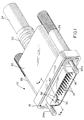
- the next step in processing the terminal module is to form or crimp gripping arms 62a and 62b into gripping engagement with the coaxial cables about the exposed metallic shields 56, as shown in Figure 8.
- the gripping arms are not crimped onto the metallic shields as is typical in the prior art.
- An amount of gripping pressure is used to form the gripping arms inwardly, only to grip or retain the coaxial cables.
- the gripping or crimping pressure should not be excessive so as to damage or deform the underlying insulating sleeves 60 and/or the dielectric material 54 to any extent, which could affect the electrical performance of the cable assembly.
- Ground plate 32 then is mechanically and electrically connected to metallic shields 56 of the coaxial cables by soldering the metallic shields to gripping arms 62a and 62b by soldering through slots 48 in the gripping arms, as at "S" in Figure 8.
- the slots are formed on the order of 0.040 inch wide to prevent the application of concentrated heat directly to the metallic shield sufficient to cause any heat damage to the underlying insulating sleeve or the dielectric. Regardless of the width of the slots, the slots should be sufficiently narrow to at least prevent whatever soldering iron or tool is used from passing through the slots and into direct engagement with the metallic shield. Such engagement might result in damage to the underlying insulating sleeve or inner dielectric.
- the slots restrict the amount of soldering heat which is transmitted inwardly.
- the slots With the slots extending in a circumferential direction and into blade portion 42 of the ground plate, the slots provide a large area of access to the metallic shields in a circumferential direction.
- the soldering slots extend approximately 180° or more about the center or axis of each respective coaxial cable.
- solder paste may be deposited in slots 48, and the solder paste can be reflowed through the subsequent application of heat.
- the slots 48 may be removed and the gripping arms may have a heavy tin coating or a solder inlay, and these materials can also be reflowed through the application of heat.
- insulating sleeves 60 function to thermally isolate dielectrics 54 and protect the dielectrics from the heat of the soldering process.
- terminal module 30 As shown in Figure 9 and described above in relation to Figure 2.
- Conductors/cores 52 of the coaxial cables are connected, as by soldering, welding or other means to the inner ends 38a of terminals 38, with terminal blocks 30a and 30b clamping blade portion 42 of ground plate 32 therebetween, as shown in Figure 2 and described above.
- the terminal module then is mounted within dielectric housing 12 as shown in Figure 2. If desired, terminal blocks 30a and 30b could be mounted to blade portion 42 of ground plate 32 prior to inserting cables 40 between gripping arms 50a and 50b. In such case, the ground plate 32 shown in Figure 6 would have the terminal blocks mounted thereon at the beginning of the termination process.
Landscapes
- Details Of Connecting Devices For Male And Female Coupling (AREA)
- Coupling Device And Connection With Printed Circuit (AREA)
- Manufacturing Of Electrical Connectors (AREA)
- Cable Accessories (AREA)
- Insulated Conductors (AREA)
Applications Claiming Priority (2)
| Application Number | Priority Date | Filing Date | Title |
|---|---|---|---|
| US08/609,577 US5725387A (en) | 1996-03-01 | 1996-03-01 | System for terminating the shield of a high speed cable |
| US609577 | 1996-03-01 |
Publications (2)
| Publication Number | Publication Date |
|---|---|
| EP0793307A2 true EP0793307A2 (fr) | 1997-09-03 |
| EP0793307A3 EP0793307A3 (fr) | 1998-11-25 |
Family
ID=24441376
Family Applications (1)
| Application Number | Title | Priority Date | Filing Date |
|---|---|---|---|
| EP97103080A Ceased EP0793307A3 (fr) | 1996-03-01 | 1997-02-26 | Système de terminaison d'écran d'un câble à grande vitesse |
Country Status (7)
| Country | Link |
|---|---|
| US (1) | US5725387A (fr) |
| EP (1) | EP0793307A3 (fr) |
| JP (1) | JP3015944B2 (fr) |
| KR (1) | KR970068031A (fr) |
| CN (1) | CN1092852C (fr) |
| SG (1) | SG54468A1 (fr) |
| TW (1) | TW326586B (fr) |
Cited By (1)
| Publication number | Priority date | Publication date | Assignee | Title |
|---|---|---|---|---|
| WO2000033430A1 (fr) * | 1998-11-30 | 2000-06-08 | The Siemon Company | Outil de preparation pour cables blindes |
Families Citing this family (28)
| Publication number | Priority date | Publication date | Assignee | Title |
|---|---|---|---|---|
| US6166919A (en) * | 1997-12-16 | 2000-12-26 | Notrel Networks Corporation | Casing mountable filler module |
| US6164986A (en) * | 1999-01-15 | 2000-12-26 | The Whitaker Corporation | Electrical connector assembly having a grounding clip |
| US6200163B1 (en) | 1999-08-30 | 2001-03-13 | Molex Incorporated | Electrical connector including means for terminating the shield of a high speed cable |
| US6186828B1 (en) | 1999-08-30 | 2001-02-13 | Molex Incorporated | Electrical connector including coaxial cable management system |
| JP3656187B2 (ja) * | 2000-04-17 | 2005-06-08 | 日本航空電子工業株式会社 | シールドケーブル用コネクタ |
| JP3477639B2 (ja) * | 2000-04-26 | 2003-12-10 | 日本航空電子工業株式会社 | ケーブル用コネクタ |
| JP2002280121A (ja) * | 2001-03-19 | 2002-09-27 | Jst Mfg Co Ltd | 電気コネクタ、および伝送路 |
| USD515508S1 (en) * | 2002-09-24 | 2006-02-21 | Monster Cable Products, Inc. | DVI connector |
| USD496632S1 (en) | 2003-11-19 | 2004-09-28 | Motorola, Inc. | Rugged USB connector |
| DE102006013490A1 (de) * | 2005-03-23 | 2006-10-05 | Yazaki Corp. | Struktur zur Koaxialkabelenden-Verarbeitung, Koaxialkabel-Abschirmungsklemme und Press-Befestigungsvorrichtung |
| KR100874190B1 (ko) * | 2007-03-29 | 2008-12-15 | (주)기가레인 | 동축접촉장치 |
| FR2914788B1 (fr) * | 2007-04-05 | 2009-07-10 | Tyco Electronics France Sas So | Ensemble porte-contacts electriques |
| US8152557B2 (en) * | 2008-07-17 | 2012-04-10 | Dearborn Group Technology | Positive locking mechanism for USB connected devices |
| TWI398992B (zh) * | 2009-03-02 | 2013-06-11 | Hon Hai Prec Ind Co Ltd | 電連接器及其組件 |
| TWM447609U (zh) * | 2012-07-20 | 2013-02-21 | Speedtech Corp | 傳輸高頻訊號之高密度連接器結構 |
| JP5935701B2 (ja) * | 2013-01-22 | 2016-06-15 | 日立金属株式会社 | 差動信号伝送用ケーブルの回路基板への接続方法 |
| CN203481476U (zh) * | 2013-08-14 | 2014-03-12 | 富士康(昆山)电脑接插件有限公司 | 线缆连接器组件 |
| US9762004B2 (en) * | 2014-03-24 | 2017-09-12 | Rocal Corporation | Shielded battery receptacle |
| JP6330587B2 (ja) * | 2014-09-04 | 2018-05-30 | 株式会社オートネットワーク技術研究所 | 通信用コネクタ |
| EP3057184B1 (fr) * | 2015-02-11 | 2017-01-25 | MD Elektronik GmbH | Procédé et dispositif de fabrication d'un câble ainsi qu'un câble fabriqué selon ledit procédé |
| DE202015100962U1 (de) * | 2015-02-27 | 2016-05-30 | Leoni Bordnetz-Systeme Gmbh | HV-Kabelsatz |
| JP6724590B2 (ja) * | 2016-06-21 | 2020-07-15 | 株式会社オートネットワーク技術研究所 | 端子および端子付き電線 |
| CN113036477B (zh) * | 2016-08-18 | 2022-09-09 | 申泰公司 | 缆线组件及制造缆线组件的方法 |
| JP6443433B2 (ja) * | 2016-12-22 | 2018-12-26 | 第一精工株式会社 | コネクタ及びコネクタの製造方法 |
| EP3612671B1 (fr) * | 2017-04-21 | 2022-10-12 | Pilz GmbH & Co. KG | Tricot de forme et utilisation d'un tricot de forme |
| US10541521B1 (en) * | 2018-08-25 | 2020-01-21 | Sigma Innovations LLC | Housing assembly |
| JP7191127B2 (ja) | 2019-01-21 | 2022-12-16 | 株式会社ソニー・インタラクティブエンタテインメント | 信号ケーブル |
| DE102022118421A1 (de) * | 2022-07-22 | 2024-01-25 | Te Connectivity Germany Gmbh | Abschirmfederkontakt, Steckverbinder mit einem Abschirmfederkontakt, Leitungsschirmanschluss und Steckverbindersystem mit einem Abschirmfederkontakt |
Family Cites Families (27)
| Publication number | Priority date | Publication date | Assignee | Title |
|---|---|---|---|---|
| US3383457A (en) * | 1966-04-05 | 1968-05-14 | Amp Inc | Connector means for connecting coaxial cable to a printed circuit board |
| US4615578A (en) * | 1984-12-05 | 1986-10-07 | Raychem Corporation | Mass termination device and connection assembly |
| CA1279912C (fr) * | 1986-10-15 | 1991-02-05 | Toshiaki Tokizane | Connecteur pour cables haute frequence |
| US4767345A (en) * | 1987-03-27 | 1988-08-30 | Amp Incorporated | High-density, modular, electrical connector |
| DE3921990A1 (de) * | 1988-07-08 | 1990-01-11 | Yazaki Corp | Quetschanschlussverbinder fuer leiter und verfahren zur herstellung eines quetschverbinderanschlusses |
| US4993968A (en) * | 1989-03-02 | 1991-02-19 | Precision Interconnect Corporation | Economical connector system for an array of conductors |
| US4921447A (en) * | 1989-05-17 | 1990-05-01 | Amp Incorporated | Terminating a shield of a malleable coaxial cable |
| JPH0734373B2 (ja) * | 1989-11-15 | 1995-04-12 | ヒロセ電機株式会社 | コネクタ |
| US4960392A (en) * | 1990-01-16 | 1990-10-02 | Dickie Robert G | Shielded connector assembly with noise suppressor |
| US5197893A (en) * | 1990-03-14 | 1993-03-30 | Burndy Corporation | Connector assembly for printed circuit boards |
| US5083929A (en) * | 1990-04-17 | 1992-01-28 | Hewlett-Packard Company | Grounding bulkhead connector for a shielded cable |
| US5061827A (en) * | 1990-06-27 | 1991-10-29 | Amp Incorporated | Termination of a small coaxial cable |
| JPH0737261Y2 (ja) * | 1990-08-30 | 1995-08-23 | ヒロセ電機株式会社 | 電気コネクタ |
| JPH0452368U (fr) * | 1990-09-10 | 1992-05-01 | ||
| JPH0452370U (fr) * | 1990-09-10 | 1992-05-01 | ||
| JPH0722054Y2 (ja) * | 1990-09-11 | 1995-05-17 | ヒロセ電機株式会社 | 電気コネクタ |
| NL9101695A (nl) * | 1991-10-09 | 1993-05-03 | Burndy Electra Nv | Contact voor een kabel met een of meer binnengeleiders. |
| US5180316A (en) * | 1991-03-25 | 1993-01-19 | Molex Incorporated | Shielded electrical connector |
| JPH0636818A (ja) * | 1992-07-16 | 1994-02-10 | Amp Japan Ltd | 電気コンタクト及びそれを使用する電気コネクタ |
| US5197904A (en) * | 1992-09-04 | 1993-03-30 | Michael Gold | Connector for coaxially shielded cables |
| US5315063A (en) * | 1992-09-10 | 1994-05-24 | Electric Motion Company, Inc. | Ground connector |
| US5222898A (en) * | 1992-10-01 | 1993-06-29 | The Whitaker Corporation | Modular cable assembly |
| US5304069A (en) * | 1993-07-22 | 1994-04-19 | Molex Incorporated | Grounding electrical connectors |
| ATE311748T1 (de) * | 1993-09-29 | 2005-12-15 | Dsm Ip Assets Bv | Modifizierte formen des natamycins, verfahren zu ihrer herstellung und sie enthaltende antifungale zusammensetzungen |
| FR2718299B1 (fr) * | 1994-03-30 | 1996-05-31 | Telemecanique | Prise de masse sur blindage de câble électrique. |
| JPH0845575A (ja) * | 1994-07-29 | 1996-02-16 | Sumitomo Wiring Syst Ltd | シールド線の端末処理構造および端末処理方法 |
| US5509827A (en) * | 1994-11-21 | 1996-04-23 | Cray Computer Corporation | High density, high bandwidth, coaxial cable, flexible circuit and circuit board connection assembly |
-
1996
- 1996-03-01 US US08/609,577 patent/US5725387A/en not_active Expired - Fee Related
-
1997
- 1997-02-20 SG SG1997000373A patent/SG54468A1/en unknown
- 1997-02-21 TW TW086102097A patent/TW326586B/zh active
- 1997-02-26 EP EP97103080A patent/EP0793307A3/fr not_active Ceased
- 1997-02-28 CN CN97110044A patent/CN1092852C/zh not_active Expired - Fee Related
- 1997-02-28 KR KR1019970006836A patent/KR970068031A/ko not_active Ceased
- 1997-02-28 JP JP9087136A patent/JP3015944B2/ja not_active Expired - Fee Related
Cited By (3)
| Publication number | Priority date | Publication date | Assignee | Title |
|---|---|---|---|---|
| WO2000033430A1 (fr) * | 1998-11-30 | 2000-06-08 | The Siemon Company | Outil de preparation pour cables blindes |
| US6324945B1 (en) | 1998-11-30 | 2001-12-04 | The Siemon Company | Preparation tool for shielded cables |
| US6505399B2 (en) | 1998-11-30 | 2003-01-14 | The Siemon Company | Method for preparation of shielded cables |
Also Published As
| Publication number | Publication date |
|---|---|
| MX9701565A (es) | 1997-09-30 |
| US5725387A (en) | 1998-03-10 |
| KR970068031A (ko) | 1997-10-13 |
| CN1168550A (zh) | 1997-12-24 |
| EP0793307A3 (fr) | 1998-11-25 |
| CN1092852C (zh) | 2002-10-16 |
| JPH1041021A (ja) | 1998-02-13 |
| JP3015944B2 (ja) | 2000-03-06 |
| SG54468A1 (en) | 1998-11-16 |
| TW326586B (en) | 1998-02-11 |
Similar Documents
| Publication | Publication Date | Title |
|---|---|---|
| US5725387A (en) | System for terminating the shield of a high speed cable | |
| US5823825A (en) | System for terminating the shield of a high speed cable | |
| US5718607A (en) | System for terminating the shield of a high speed cable | |
| US5716236A (en) | System for terminating the shield of a high speed cable | |
| US5711686A (en) | System for terminating the shield of a high speed cable | |
| US5961348A (en) | System for terminating the shield of a high speed cable | |
| US5785555A (en) | System for terminating the shield of a high speed cable | |
| US4634208A (en) | Electrical plug connector and method of terminating a cable therewith | |
| US5768771A (en) | System for terminating the shield of a high speed cable | |
| MXPA97001560A (en) | System to complete the protection of a cable dealta veloci | |
| EP0542075B1 (fr) | Procédé pour terminer un connecteur électrique miniature coaxial et un connecteur terminé selon le procédé | |
| US6364701B1 (en) | System for terminating the shield of a high speed cable | |
| MXPA97001565A (en) | System to complete the shield of a cable aalta veloci | |
| MXPA97001563A (en) | System to complete the shield of a high speed cable |
Legal Events
| Date | Code | Title | Description |
|---|---|---|---|
| PUAI | Public reference made under article 153(3) epc to a published international application that has entered the european phase |
Free format text: ORIGINAL CODE: 0009012 |
|
| AK | Designated contracting states |
Kind code of ref document: A2 Designated state(s): DE FR GB IT NL |
|
| PUAL | Search report despatched |
Free format text: ORIGINAL CODE: 0009013 |
|
| AK | Designated contracting states |
Kind code of ref document: A3 Designated state(s): DE FR GB IT NL |
|
| 17P | Request for examination filed |
Effective date: 19990429 |
|
| 17Q | First examination report despatched |
Effective date: 20000925 |
|
| GRAG | Despatch of communication of intention to grant |
Free format text: ORIGINAL CODE: EPIDOS AGRA |
|
| STAA | Information on the status of an ep patent application or granted ep patent |
Free format text: STATUS: THE APPLICATION HAS BEEN REFUSED |
|
| 18R | Application refused |
Effective date: 20011206 |
|
| RIN1 | Information on inventor provided before grant (corrected) |
Inventor name: MURPHY, PAUL Inventor name: MANCHESTER, GARY S. Inventor name: BRUNKER, DAVID L. Inventor name: O'SULLIVAN, MICHAEL |