EP0793561B1 - Einrichtung zum greifen und fördern von blattmaterial sowie ein damit versehener manipulator - Google Patents
Einrichtung zum greifen und fördern von blattmaterial sowie ein damit versehener manipulator Download PDFInfo
- Publication number
- EP0793561B1 EP0793561B1 EP95938428A EP95938428A EP0793561B1 EP 0793561 B1 EP0793561 B1 EP 0793561B1 EP 95938428 A EP95938428 A EP 95938428A EP 95938428 A EP95938428 A EP 95938428A EP 0793561 B1 EP0793561 B1 EP 0793561B1
- Authority
- EP
- European Patent Office
- Prior art keywords
- well
- sucker
- lip
- work piece
- border
- Prior art date
- Legal status (The legal status is an assumption and is not a legal conclusion. Google has not performed a legal analysis and makes no representation as to the accuracy of the status listed.)
- Expired - Lifetime
Links
- 239000000463 material Substances 0.000 title claims description 11
- 239000002184 metal Substances 0.000 claims description 20
- 230000002093 peripheral effect Effects 0.000 claims description 9
- 239000011248 coating agent Substances 0.000 claims description 7
- 238000000576 coating method Methods 0.000 claims description 7
- 238000007789 sealing Methods 0.000 claims description 6
- 239000002783 friction material Substances 0.000 claims description 5
- 239000003566 sealing material Substances 0.000 claims description 4
- 239000013536 elastomeric material Substances 0.000 claims description 3
- 238000004073 vulcanization Methods 0.000 claims description 2
- 241000252254 Catostomidae Species 0.000 description 9
- 238000005452 bending Methods 0.000 description 8
- 238000004080 punching Methods 0.000 description 2
- 230000000284 resting effect Effects 0.000 description 2
- 238000010008 shearing Methods 0.000 description 2
- 230000003068 static effect Effects 0.000 description 2
- 238000004891 communication Methods 0.000 description 1
- 238000010276 construction Methods 0.000 description 1
- 230000008602 contraction Effects 0.000 description 1
- 229910001234 light alloy Inorganic materials 0.000 description 1
- 230000014759 maintenance of location Effects 0.000 description 1
- 238000005096 rolling process Methods 0.000 description 1
Images


Classifications
-
- B—PERFORMING OPERATIONS; TRANSPORTING
- B25—HAND TOOLS; PORTABLE POWER-DRIVEN TOOLS; MANIPULATORS
- B25B—TOOLS OR BENCH DEVICES NOT OTHERWISE PROVIDED FOR, FOR FASTENING, CONNECTING, DISENGAGING OR HOLDING
- B25B11/00—Work holders not covered by any preceding group in the subclass, e.g. magnetic work holders, vacuum work holders
- B25B11/005—Vacuum work holders
-
- B—PERFORMING OPERATIONS; TRANSPORTING
- B21—MECHANICAL METAL-WORKING WITHOUT ESSENTIALLY REMOVING MATERIAL; PUNCHING METAL
- B21D—WORKING OR PROCESSING OF SHEET METAL OR METAL TUBES, RODS OR PROFILES WITHOUT ESSENTIALLY REMOVING MATERIAL; PUNCHING METAL
- B21D43/00—Feeding, positioning or storing devices combined with, or arranged in, or specially adapted for use in connection with, apparatus for working or processing sheet metal, metal tubes or metal profiles; Associations therewith of cutting devices
- B21D43/02—Advancing work in relation to the stroke of the die or tool
- B21D43/18—Advancing work in relation to the stroke of the die or tool by means in pneumatic or magnetic engagement with the work
-
- B—PERFORMING OPERATIONS; TRANSPORTING
- B65—CONVEYING; PACKING; STORING; HANDLING THIN OR FILAMENTARY MATERIAL
- B65G—TRANSPORT OR STORAGE DEVICES, e.g. CONVEYORS FOR LOADING OR TIPPING, SHOP CONVEYOR SYSTEMS OR PNEUMATIC TUBE CONVEYORS
- B65G47/00—Article or material-handling devices associated with conveyors; Methods employing such devices
- B65G47/74—Feeding, transfer, or discharging devices of particular kinds or types
- B65G47/90—Devices for picking-up and depositing articles or materials
- B65G47/91—Devices for picking-up and depositing articles or materials incorporating pneumatic, e.g. suction, grippers
Definitions
- the present invention relates to a device according to the preamble of claim 1, for gripping and handling pieces of sheet material, of the kind comprising a transfer unit that can be moved towards and away from a face of the work piece and can also be moved along a path which the work piece is to follow, and that carries at least one sucker having a flexible peripheral wall with a peripheral lip intended to be placed against a face of the work piece and whose interior is connected to a vacuum source.
- Gripping and handling devices especially those designed for use with stock in sheet form, such as sheet metal pieces or panels, are very useful for transferring the work pieces from one point to another provided positioning does not have to be too accurate, for unfortunately the very flexibility of suckers makes them prone to sideways movements, so that it is impossible to position the work pieces with any great accuracy.
- Situations where this is relevant include, for example, the need for accurate positioning of sheet metal or other kinds of sheet material in relation to a machine tool in order to carry out bending, shearing, punching and other such operations.
- sucker-type gripping and handling devices are not used to manipulate work pieces reguiring to be positioned with extreme accuracy.
- the invention has been developed in its application to manipulators on numerically controlled sheet metal bending presses, but is not limited to this application.
- Presses of this kind are programmed to make a series of accurately positioned bends in a sheet metal panel which can be achieved by numerical control not only of the press but also of the manipulator.
- the same problem exists for example in shearing and punching presses operating not only on sheet metal but also on cardboard.
- a device according to the preamble of claim 1 is for instance known from US-A-4600229.
- the object of the present invention is to provide a device for gripping and handling pieces of sheet material, of the type outlined earlier, which uses suckers and makes it possible to achieve an extremely firm and accurate grip on the work piece and in which the wear to which the sucker lips are subject is of negligible influence and in any case takes a very long time to develop.
- this object is achieved by means of a device as defined in claim 1.
- a gripping and handling device constructed on these lines has the ability to operate as follows:
- the invention also relates to a manipulator of pieces of sheet material comprising the claimed gripping and handling device.
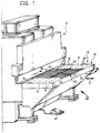
- the numeral 10 indicates a sheet metal bending press as a whole.
- the press may for example be of the kind disclosed and illustrated in document EP-A-0 298 056.
- a feed table indicated 12 At the front of the press 10 is a feed table indicated 12 as a whole.
- the feed table 12 incorporates a manipulator which will be described later with reference to Figure 2.
- the manipulator includes a supporting surface 14 that forms part of the table 12 and is intended to hold sheet metal pieces or panels on which the press 10 will execute a number of bends.
- the supporting surface 14 comprises two static lateral parts 16 fitted with rolling balls 18 of a known kind to facilitate the sliding of the sheet metal pieces.
- a discontinuity or gap 20 that contains a grating-like structure of parallel bars 22 which also support the sheet metal pieces.
- the bars 22 are orientated in the direction shown by the double arrow X, which is the direction in which the work piece is fed to the punches and dies of the press 10.
- the manipulator 26 comprises a sturdy frame 28 mounted on the frame of the press 10.
- the frame 28 includes among other things a strong horizontal guide beam 30 along which a saddle 32 travels in the directions indicated by the double arrow X.
- the movements of the saddle 32 are brought about by a numerical-control motor 34 acting through a toothed belt drive 36 and a traversing screw 38 which engages with a nut (not shown) incorporated in the saddle 32.
- a hydraulic or pneumatic linear actuator or cylinder 40 is also incorporated in the saddle 32, the axis of which is vertical.
- a cross member 42 parallel with the front of the press 10, moves vertically on the saddle 32 in the directions of the double arrow Z and is supported by the rod 44 of the cylinder 40 to bring about the up and down movements of the cross member.
- the cross member 42 in turn carries the series of transfer units 24.
- a numerical-control apparatus is set up so as to bring about, according to a previously determined program, the movements of the punches and dies of the press 10 and also, through the motor 34, the advancing and retreating movements indicated by the double arrow X of the transfer units 24 in the spaces between the bars 22 shown in Figure 1.
- the transfer blocks could be mobile in other directions, for example using Cartesian coordinates to execute sideways transferring movements of the work piece as well.
- the press operator Before commencing a bending cycle, the press operator first lays the sheet metal piece or panel on the supporting surface 14 in a reference or “zero" position determined by stops (not illustrated) . This "zero" position is recorded by the numerical-control apparatus.
- the numeral 43 denotes a pedal for starting a cycle of bending a sheet metal piece or panel laid on the supporting surface 14.
- the press operator depresses the pedal 43 in order to commence the bending cycle.
- This operation firstly causes the cross member 42 and its transfer units 24 to rise until they are placed against the lower face of the panel, as will be explained in more detail later with reference to the subsequent figures.
- the numerical-control apparatus automatically initiates a cycle, the transfer units 24 introduce the sheet metal panel into the press 10 to the desired depth for the first bend, and the press 10 executes this bend.
- the cycle then continues automatically by carrying out all the subsequent parallel bends required, after which the transfer units 24 are retracted until the bent panel is out of the press 10.
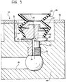
- Figure 3 also shows at 22 one of the bars of the supporting surface 14, the balls of which are also shown at 18.
- P is a sheet metal panel or work piece which, at the start of the cycle, rests on the balls 18.
- the transfer unit 24 preferably comprises a generally prismatic block 44 made of a light alloy or other metal.
- the block 44 contains manifold channels 46 which are connected to a vacuum source, not illustrated.
- Sunk into the top of the block 44 is an array of cylindrical wells 48 open on the top. Located concentrically in each of these wells is a sucker 50 whose top end is likewise open.
- the manifold channel 46 leads to a nozzle 52 with an axial communicating channel 54 of comparatively large cross section.
- the nozzle 52 comprises a threaded lower end 56 by which it is mounted in the block 44 and an upper core 58 that tapers in two directions.
- the sucker 50 which is of rubber or the like, comprises a flexible peripheral wall 60.
- the wall 60 is concertina-shaped to facilitate its axial contraction and expansion.
- the lower part of the wall 60 fits securely around the core 58 of the nozzle 52.
- the channel 54 of the nozzle 52 continues upwards with a narrow axial channel 64 leading into the interior of the sucker 50.
- the nozzle 52 Between its lower end 56 and its core 58, the nozzle 52 has a collar 66 applied against the bottom of the well 48 and containing a narrow radial channel 68.
- the narrow channel 68 gives communication between the communicating channel 54 and the internal space of the well 48 around the sucker 50. This space is marked 70.
- the block 44 of the transfer unit 24 has a flat upper face into which the wells 48 are sunk and to which a coating 72 of a sealing and friction material is applied to form a border for each well 48 concentrically about the sucker 50.
- the coating 72 is preferably an elastomeric material bonded to the metal block 34 by vulcanization.
- the thickness of the coating 72 is a few tenths of a millimetre (e.g. 0.6 mm), so that the coating can fully develop its characteristics as both a sealing and a friction material without becoming significantly compressed.
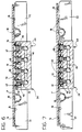
- the pressure on the pedal 43 causes the cylinder 40 shown in Figure 2 to begin to raise the transfer units 24 bringing them firstly into the position illustrated in Figure 6 in which the lips 62 of the suckers 50 are brought up against the panel P, which is still resting on the balls 18. Because of the vacuum created inside the suckers 50, the latter cling to the panel P and thus prevent it from sliding over the supporting surface 14.
- the transfer units 24 then continue to rise into the position illustrated in Figure 7.
- the suckers 50 come into a contracted state in which their lips 62 are coplanar with the borders of the wells 48.
- suckers 50 which in their expanded position as shown in Figure 7 are exerting all of the grip on the panel P, are no longer under stress when contracted in the position of Figure 8 since the same depression is present both inside them and in the space 70 around them.
- the channels 64 and 68 are preferably no more than 1 mm in diameter and still more preferably about 0.25 mm in diameter, thus being as it were capillary channels.
Landscapes
- Engineering & Computer Science (AREA)
- Mechanical Engineering (AREA)
- Manipulator (AREA)
- Feeding Of Articles By Means Other Than Belts Or Rollers (AREA)
- Sheets, Magazines, And Separation Thereof (AREA)
- Jigs For Machine Tools (AREA)
- Bending Of Plates, Rods, And Pipes (AREA)
Claims (7)
- Vorrichtung zum Ergreifen und Bewegen von Teilen (P) aus Plattenmaterial, die eine Überführungseinheit (24) umfaßt, die auf eine Fläche des Werkstücks (P) zu und davon weg bewegt werden kann und darüber hinaus auf einem Weg bewegt werden kann, dem das Werkstück (P) folgen soll, und die wenigstens eine Saugeinrichtung (50) mit einer flexiblen Umfangswand (60) mit einem Umfangsrand (62) trägt, der an eine Fläche des Werkstücks (P) angelegt werden soll, und deren Inneres mit einer Vakuumquelle verbunden ist, wobei die Überführungseinheit (24) für die Saugeinrichtung bzw. für jede Saugeinrichtung (50) eine Vertiefung (48) umfaßt, die Vertiefung bzw. jede Vertiefung (48) eine Umrandung (72) umfaßt, die aus einem Abdicht- und Reibungsmaterial besteht und konzentrisch zum Rand (62) der Saugeinrichtung (50) ist, wobei die Vertiefung (48) im wesentlichen nicht zusammengedrückt werden kann, die Umfangswand (60) der Saugeinrichtung (50) so flexibel ist, daß sie axiale Bewegung des Randes (62) zwischen einer ausgedehnten Position, in der der Rand (62) über die Umrandung (72) der Vertiefung (48) vorsteht, und einer eingezogenen Position, in der der Rand (62) koplanar mit dieser Umrandung ist, ermöglicht, dadurch gekennzeichnet, daß die bzw. jede Saugeinrichtung mittig in der bzw. jeder Vertiefung (48) angeordnet ist, dadurch, daß der Innenraum der Saugeinrichtung (50) und der Innenraum (70) der Vertiefung (48) um die Saugeinrichtung (50) herum beide mit der Vakuumquelle durch entsprechende schmale Kanäle (64, 68) verbunden sind, deren Querschnitte einander ungefähr entsprechen, und dadurch, daß die Größe der Querschnitte der schmalen Kanäle (64, 68) bewirkt, daß der Verlust an Vakuum im Inneren der Saugeinrichtung (50) vernachlässigt werden kann, wenn das Werkstück (P) an den Rand (62) der Saugeinrichtung (50), jedoch nicht an die Umrandung (72) der Vertiefung (48) angelegt wird.
- Vorrichtung nach Anspruch 1, dadurch gekennzeichnet, daß der Durchmesser der schmalen Kanäle (64, 68), die die Saugeinrichtung (50) und die Vertiefung (48) mit der Vakuumquelle verbinden, nicht größer ist als 1 mm.
- Vorrichtung nach Anspruch 2, dadurch gekennzeichnet, daß der Durchmesser der schmalen Kanäle (64, 68) ungefähr 0,25 mm beträgt.
- Vorrichtung nach einem der vorangehenden Ansprüche, dadurch gekennzeichnet, daß die Umfangswand (60) der Saugeinrichtung (50) ziehharmonikaförmig ist.
- Vorrichtung nach einem der vorangehenden Ansprüche, dadurch gekennzeichnet, daß die Überführungseinheit (24) einen Block (44) umfaßt, der die Vertiefung bzw. jede Vertiefung (48) enthält, und die Umrandung der Vertiefung bzw. jeder Vertiefung (48) aus einer Beschichtung aus Elastomermaterial (72) besteht, das auf eine plane Fläche des Blocks (44) aufgetragen wird, in die die Vertiefung bzw. jede Vertiefung (48) eingelassen ist.
- Vorrichtung nach Anspruch 5, dadurch gekennzeichnet, daß der Block (44) der Überführungseinheit (24) aus Metall besteht, und daß die Beschichtung (72) aus Elastomermaterial durch Vulkanisierung an die Einheit angeklebt wird.
- Manipulator für Werkstücke (P) aus Plattenmaterial, dadurch gekennzeichnet, daß er wenigstens eine Greif- und Bewegungsvorrichtung mit einer bzw. mehrerer Überführungseinheiten (24) nach einem der vorangehenden Ansprüche umfaßt sowie eine Fläche (14), die das Werkstück (P) aufnimmt, und die innerhalb ihres Umfangs wenigstens eine Unbrechung (20) aufweist, in der wenigstens eine der Überführungseinheiten (24) angeordnet ist, dadurch, daß die bzw. jede Überführungseinheit (24) sowohl in wenigstens einer Richtung (X) parallel zu der Aufnahmefläche (14) als auch in einer Richtung (Z) senkrecht zur Aufnahmefläche (14) zwischen einer eingezogenen Position, in der sich der Rand (62) der Saugeinrichtung bzw. jeder Saugeinrichtung (50) unter der Aufnahmefläche (14) befindet, und einer ausgefahrenen Position bewegt werden kann, wobei die Abdicht- und Reibungsumrandung (72) der Vertiefung bzw. jeder Vertiefung (48) über die Aufnahmefläche (14) vorsteht, dadurch, daß er eine Vakuumquelle, die mit der Saugeinrichtung bzw. jeder Saugeinrichtung (50) und der Vertiefung bzw. jeder Vertiefung (48) verbunden ist oder wahlweise verbunden werden kann, umfaßt bzw. damit verbunden ist, und daß er des weiteren eine Einrichtung (34, 40) umfaßt, die die bzw. jede Überführungseinheit (24) in die Bewegungen in den Richtungen (X, Z) parallel und senkrecht zu der Aufnahmefläche (14) versetzt.
Applications Claiming Priority (3)
| Application Number | Priority Date | Filing Date | Title |
|---|---|---|---|
| ITTO940885 | 1994-11-09 | ||
| IT94TO000885A IT1267490B1 (it) | 1994-11-09 | 1994-11-09 | Dispositivo di presa e movimentazione di pezzi di materiale in foglio e manipolatore di pezzi di materiale in foglio comprendente tale |
| PCT/EP1995/004371 WO1996014965A1 (en) | 1994-11-09 | 1995-11-07 | Device for gripping and handling pieces of sheet material and manipulator of pieces of sheet material comprising this device |
Publications (2)
| Publication Number | Publication Date |
|---|---|
| EP0793561A1 EP0793561A1 (de) | 1997-09-10 |
| EP0793561B1 true EP0793561B1 (de) | 1999-02-24 |
Family
ID=11412877
Family Applications (1)
| Application Number | Title | Priority Date | Filing Date |
|---|---|---|---|
| EP95938428A Expired - Lifetime EP0793561B1 (de) | 1994-11-09 | 1995-11-07 | Einrichtung zum greifen und fördern von blattmaterial sowie ein damit versehener manipulator |
Country Status (6)
| Country | Link |
|---|---|
| US (1) | US5964568A (de) |
| EP (1) | EP0793561B1 (de) |
| JP (1) | JPH10508545A (de) |
| DE (1) | DE69507964T2 (de) |
| IT (1) | IT1267490B1 (de) |
| WO (1) | WO1996014965A1 (de) |
Families Citing this family (23)
| Publication number | Priority date | Publication date | Assignee | Title |
|---|---|---|---|---|
| IT1293382B1 (it) | 1997-06-23 | 1999-03-01 | Antonio Codatto | Dispositivo per l'azionamento in rotazione di un braccio brandeggiabile attorno ad un asse verticolare, quale un braccio di |
| DE19943916A1 (de) * | 1999-09-14 | 2001-03-15 | Volkswagen Ag | Vorrichtung zum gegenseitigen Verspannen von Blechwerkstücken |
| US6152444A (en) * | 1999-10-27 | 2000-11-28 | Hewlett-Packard Company | Shuttling media movement system for hardcopy devices |
| US6419291B1 (en) | 2001-02-26 | 2002-07-16 | John Preta | Adjustable flexible vacuum gripper and method of gripping |
| DE10116609A1 (de) * | 2001-04-03 | 2002-11-07 | Roland Man Druckmasch | Vorrichtung zur Erzeugung einer hülsenförmigen Druckform |
| ITMI20011032A1 (it) * | 2001-05-17 | 2002-11-17 | Alberti Vittorio Spa | Macchina foratrice e fresatrice particolarmente studiata per l'applicazione di ferramenta ed elementi di mobili |
| DE10159921A1 (de) * | 2001-12-06 | 2003-06-18 | Imt Robot Ag | Objektgreifer für die Automatisierungstechnik |
| AT500767B1 (de) * | 2003-04-30 | 2009-01-15 | Electrovac Ag | Spannvorrichtung |
| TWI241976B (en) * | 2004-05-27 | 2005-10-21 | Quanta Display Inc | Substrate transporting apparatus |
| JP5610330B2 (ja) * | 2005-09-15 | 2014-10-22 | コアフロー サイエンティフィック ソリューションズ リミテッド | コンベアの搬送性能を強化するシステム |
| DE102006023111A1 (de) * | 2006-05-16 | 2007-11-22 | Werner Kammann Maschinenfabrik Gmbh & Co. Kg | Vorrichtung zum Beschichten von Objekten |
| JP4486943B2 (ja) * | 2006-05-31 | 2010-06-23 | シャープ株式会社 | 被加工脆性板の切断装置および切断方法 |
| US8604605B2 (en) | 2007-01-05 | 2013-12-10 | Invensas Corp. | Microelectronic assembly with multi-layer support structure |
| ITUD20070052A1 (it) * | 2007-03-07 | 2008-09-08 | Antonio Codatto | Impianto per la piegatura di elementi metallici piani, quali pannelli, lamiere, piastre o simili, macchina piegatrice per tali elementi metallici piani e relativo procedimento di piegatura |
| US8740487B2 (en) * | 2007-05-03 | 2014-06-03 | Hewlett-Packard Development Company, L.P. | Printers |
| KR101019948B1 (ko) * | 2010-09-17 | 2011-03-09 | 한국뉴매틱(주) | 흡입식 그리퍼 장치 |
| AT511627B1 (de) * | 2011-07-01 | 2015-05-15 | Mechatronic Systemtechnik Gmbh | Vorrichtung zum halten eines flächigen substrats |
| CN105415235B (zh) * | 2015-12-11 | 2017-04-12 | 哈尔滨工程大学 | 一种自锁式柔性点阵吸盘 |
| DE102016110542B4 (de) * | 2016-06-08 | 2018-09-13 | J. Schmalz Gmbh | Be- und Entladevorrichtung für eine Maschine, Maschine zum Bearbeiten von plattenförmigen Werkstücken sowie Werkstückauflage für eine solche Maschine und Verfahren zum Be- und Entladen einer solchen Maschine |
| KR102652044B1 (ko) | 2018-11-21 | 2024-03-29 | 주식회사 엘지화학 | 이차전지용 리드탭, 이의 제조 장치, 및 이를 포함하는 이차전지 |
| CN110076256A (zh) * | 2019-05-24 | 2019-08-02 | 广义智能智造(深圳)有限公司 | 一种折弯机自动上下料装置 |
| CN114433686B (zh) * | 2022-01-20 | 2022-09-09 | 安徽择正公路工程有限责任公司 | 一种标志牌生产用平板铝板的弯折设备及弯折方法 |
| CN116040313B (zh) * | 2023-03-30 | 2023-06-13 | 中南大学 | 可调吸速双变腔体适应性气动吸附装置 |
Family Cites Families (12)
| Publication number | Priority date | Publication date | Assignee | Title |
|---|---|---|---|---|
| FR2287400A1 (fr) * | 1974-10-11 | 1976-05-07 | Saint Gobain | Dispositif de support des bords lateraux d'un vitrage et application de ce dispositif |
| US4354796A (en) * | 1976-05-10 | 1982-10-19 | Bergman Raymond A | Air float power translation system |
| US4600229A (en) * | 1984-08-03 | 1986-07-15 | Oten Peter D | Vacuum cup |
| DE3500342C2 (de) * | 1985-01-08 | 1987-03-19 | Reinhard Dipl.-Ing. 3070 Nienburg Göpfert | Vorrichtung zum Anheben und Versetzen von Hebegut |
| DE8628039U1 (de) * | 1986-10-21 | 1987-02-05 | Sauermann, Hans, 8071 Ernsgaden | Messaufspannvorrichtung |
| DE8703223U1 (de) * | 1987-03-03 | 1987-04-16 | Modellbau Paul Apitz, 7913 Senden | Vakuum-Spannplatte |
| IT1222347B (it) * | 1987-07-03 | 1990-09-05 | Antonio Codatto | Pressa piegatrice per lamiere |
| US5207553A (en) * | 1992-02-26 | 1993-05-04 | Haruo Konagai | Suction lifting device for flat workpieces |
| DE4215140A1 (de) * | 1992-05-08 | 1993-11-11 | Georg Geis Maschinenfabrik | Spanntisch für Fräsmaschinen |
| EP0585508A1 (de) * | 1992-09-03 | 1994-03-09 | SAPRI S.p.A. | Vorrichtung zum Greifen von dünnen, plattenförmigen Werkstücken |
| JP2543652B2 (ja) * | 1993-01-18 | 1996-10-16 | 株式会社テンリュウテクニックス | 部品吸着固定装置 |
| JP3797571B2 (ja) * | 1996-12-03 | 2006-07-19 | Smc株式会社 | ワーク吸着装置 |
-
1994
- 1994-11-09 IT IT94TO000885A patent/IT1267490B1/it active IP Right Grant
-
1995
- 1995-11-07 WO PCT/EP1995/004371 patent/WO1996014965A1/en not_active Ceased
- 1995-11-07 JP JP8515705A patent/JPH10508545A/ja active Pending
- 1995-11-07 DE DE69507964T patent/DE69507964T2/de not_active Expired - Fee Related
- 1995-11-07 EP EP95938428A patent/EP0793561B1/de not_active Expired - Lifetime
- 1995-11-07 US US08/836,306 patent/US5964568A/en not_active Expired - Fee Related
Also Published As
| Publication number | Publication date |
|---|---|
| JPH10508545A (ja) | 1998-08-25 |
| WO1996014965A1 (en) | 1996-05-23 |
| ITTO940885A0 (it) | 1994-11-09 |
| DE69507964D1 (de) | 1999-04-01 |
| DE69507964T2 (de) | 1999-06-24 |
| EP0793561A1 (de) | 1997-09-10 |
| US5964568A (en) | 1999-10-12 |
| IT1267490B1 (it) | 1997-02-05 |
| ITTO940885A1 (it) | 1996-05-09 |
Similar Documents
| Publication | Publication Date | Title |
|---|---|---|
| EP0793561B1 (de) | Einrichtung zum greifen und fördern von blattmaterial sowie ein damit versehener manipulator | |
| EP1844871B1 (de) | Pressverfahren mit einem Stanzstufe und Pressvorrichtung mit einem bewegbaren Stanz | |
| EP0897766B1 (de) | Tisch zur Bestimmung der Position eines Werkstückes aus Metallblech in einem System zur Herstellung von abgekanteten Blechartikeln | |
| KR20080081708A (ko) | 누적공차 최소화 및 다기종 센터링기능이 구비되는 이송및 삽입 적재장치 및 방법 | |
| US5993144A (en) | Complex-type article conveying apparatus | |
| US5048816A (en) | Workpiece registration system and method for determining the position of a sheet | |
| KR920700852A (ko) | 금속시트굽힘 설비용 로보트 매니플레이터의 제어장치 | |
| US4059212A (en) | Stock feeder for punched stock | |
| WO1985000766A1 (en) | Improvements in bending machines | |
| JP2785597B2 (ja) | タンデムプレスラインのワーク搬送方法 | |
| US4588183A (en) | Sheet feeding apparatus | |
| JP3618162B2 (ja) | プレス装置 | |
| CN213495729U (zh) | 一种板材平面度整形机 | |
| CN113828673B (zh) | 折弯机 | |
| JPH01284438A (ja) | 板材の位置決め装置 | |
| KR102472165B1 (ko) | 홀더 결합형 캔손잡이 제조 장치 | |
| JP3968654B2 (ja) | 長尺材搬送装置 | |
| CN218927793U (zh) | 一种侧夹钳机械手 | |
| JPH04729B2 (de) | ||
| EP1107081A2 (de) | Vorrichtung zur Erzeugung von Programmen | |
| KR100494913B1 (ko) | 자동 버퍼 적재장치 | |
| CN213970182U (zh) | 托盘夹取定位装置 | |
| JPH0353775Y2 (de) | ||
| JP4188476B2 (ja) | 折曲げ加工機におけるワーク位置決め方法及びその装置 | |
| KR200158568Y1 (ko) | 블랭킹 프레스다이의 판재 드라이버장치 |
Legal Events
| Date | Code | Title | Description |
|---|---|---|---|
| PUAI | Public reference made under article 153(3) epc to a published international application that has entered the european phase |
Free format text: ORIGINAL CODE: 0009012 |
|
| 17P | Request for examination filed |
Effective date: 19970602 |
|
| AK | Designated contracting states |
Kind code of ref document: A1 Designated state(s): DE FR GB IT |
|
| GRAG | Despatch of communication of intention to grant |
Free format text: ORIGINAL CODE: EPIDOS AGRA |
|
| 17Q | First examination report despatched |
Effective date: 19980126 |
|
| GRAG | Despatch of communication of intention to grant |
Free format text: ORIGINAL CODE: EPIDOS AGRA |
|
| GRAH | Despatch of communication of intention to grant a patent |
Free format text: ORIGINAL CODE: EPIDOS IGRA |
|
| GRAH | Despatch of communication of intention to grant a patent |
Free format text: ORIGINAL CODE: EPIDOS IGRA |
|
| RAP1 | Party data changed (applicant data changed or rights of an application transferred) |
Owner name: AMADA COMPANY, LTD. |
|
| GRAA | (expected) grant |
Free format text: ORIGINAL CODE: 0009210 |
|
| AK | Designated contracting states |
Kind code of ref document: B1 Designated state(s): DE FR GB IT |
|
| ITF | It: translation for a ep patent filed | ||
| REF | Corresponds to: |
Ref document number: 69507964 Country of ref document: DE Date of ref document: 19990401 |
|
| ET | Fr: translation filed | ||
| PLBE | No opposition filed within time limit |
Free format text: ORIGINAL CODE: 0009261 |
|
| STAA | Information on the status of an ep patent application or granted ep patent |
Free format text: STATUS: NO OPPOSITION FILED WITHIN TIME LIMIT |
|
| 26N | No opposition filed | ||
| REG | Reference to a national code |
Ref country code: GB Ref legal event code: IF02 |
|
| PGFP | Annual fee paid to national office [announced via postgrant information from national office to epo] |
Ref country code: FR Payment date: 20031128 Year of fee payment: 9 |
|
| PGFP | Annual fee paid to national office [announced via postgrant information from national office to epo] |
Ref country code: GB Payment date: 20041014 Year of fee payment: 10 |
|
| PGFP | Annual fee paid to national office [announced via postgrant information from national office to epo] |
Ref country code: DE Payment date: 20041020 Year of fee payment: 10 |
|
| PG25 | Lapsed in a contracting state [announced via postgrant information from national office to epo] |
Ref country code: FR Free format text: LAPSE BECAUSE OF NON-PAYMENT OF DUE FEES Effective date: 20050729 |
|
| REG | Reference to a national code |
Ref country code: FR Ref legal event code: ST |
|
| PG25 | Lapsed in a contracting state [announced via postgrant information from national office to epo] |
Ref country code: IT Free format text: LAPSE BECAUSE OF NON-PAYMENT OF DUE FEES;WARNING: LAPSES OF ITALIAN PATENTS WITH EFFECTIVE DATE BEFORE 2007 MAY HAVE OCCURRED AT ANY TIME BEFORE 2007. THE CORRECT EFFECTIVE DATE MAY BE DIFFERENT FROM THE ONE RECORDED. Effective date: 20051107 Ref country code: GB Free format text: LAPSE BECAUSE OF NON-PAYMENT OF DUE FEES Effective date: 20051107 |
|
| PG25 | Lapsed in a contracting state [announced via postgrant information from national office to epo] |
Ref country code: DE Free format text: LAPSE BECAUSE OF NON-PAYMENT OF DUE FEES Effective date: 20060601 |
|
| GBPC | Gb: european patent ceased through non-payment of renewal fee |
Effective date: 20051107 |