EP0793609B1 - Geschwindigkeitsbegrenzer für kisten oder paletten, die unterschiedlich beladen sind und durch schwerkraft auf einer geneigten, mit rollen versehenen, ebene bewegt werden - Google Patents
Geschwindigkeitsbegrenzer für kisten oder paletten, die unterschiedlich beladen sind und durch schwerkraft auf einer geneigten, mit rollen versehenen, ebene bewegt werden Download PDFInfo
- Publication number
- EP0793609B1 EP0793609B1 EP95941753A EP95941753A EP0793609B1 EP 0793609 B1 EP0793609 B1 EP 0793609B1 EP 95941753 A EP95941753 A EP 95941753A EP 95941753 A EP95941753 A EP 95941753A EP 0793609 B1 EP0793609 B1 EP 0793609B1
- Authority
- EP
- European Patent Office
- Prior art keywords
- drum
- speed limiter
- arms
- bracket
- rollers
- Prior art date
- Legal status (The legal status is an assumption and is not a legal conclusion. Google has not performed a legal analysis and makes no representation as to the accuracy of the status listed.)
- Expired - Lifetime
Links
- 230000005484 gravity Effects 0.000 title claims description 5
- 230000033001 locomotion Effects 0.000 claims abstract description 31
- 230000000694 effects Effects 0.000 claims description 8
- 238000011144 upstream manufacturing Methods 0.000 claims description 8
- 230000008878 coupling Effects 0.000 claims description 5
- 238000010168 coupling process Methods 0.000 claims description 5
- 238000005859 coupling reaction Methods 0.000 claims description 5
- 238000006073 displacement reaction Methods 0.000 claims description 3
- 239000002184 metal Substances 0.000 claims description 2
- 230000000284 resting effect Effects 0.000 claims 3
- 230000001771 impaired effect Effects 0.000 claims 2
- 238000009434 installation Methods 0.000 description 10
- 210000000056 organ Anatomy 0.000 description 8
- 230000000903 blocking effect Effects 0.000 description 5
- 238000006243 chemical reaction Methods 0.000 description 5
- 239000000543 intermediate Substances 0.000 description 5
- 241001417494 Sciaenidae Species 0.000 description 4
- 239000000463 material Substances 0.000 description 4
- 230000001464 adherent effect Effects 0.000 description 2
- 230000006866 deterioration Effects 0.000 description 2
- 241000406668 Loxodonta cyclotis Species 0.000 description 1
- 241001674048 Phthiraptera Species 0.000 description 1
- 230000005540 biological transmission Effects 0.000 description 1
- 239000000969 carrier Substances 0.000 description 1
- 239000011248 coating agent Substances 0.000 description 1
- 238000000576 coating method Methods 0.000 description 1
- 230000004048 modification Effects 0.000 description 1
- 238000012986 modification Methods 0.000 description 1
- 239000004033 plastic Substances 0.000 description 1
- 229920003023 plastic Polymers 0.000 description 1
- 229920002635 polyurethane Polymers 0.000 description 1
- 239000004814 polyurethane Substances 0.000 description 1
- 230000000717 retained effect Effects 0.000 description 1
- 239000011435 rock Substances 0.000 description 1
- 238000000926 separation method Methods 0.000 description 1
- 230000003068 static effect Effects 0.000 description 1
Images


Classifications
-
- B—PERFORMING OPERATIONS; TRANSPORTING
- B65—CONVEYING; PACKING; STORING; HANDLING THIN OR FILAMENTARY MATERIAL
- B65G—TRANSPORT OR STORAGE DEVICES, e.g. CONVEYORS FOR LOADING OR TIPPING, SHOP CONVEYOR SYSTEMS OR PNEUMATIC TUBE CONVEYORS
- B65G13/00—Roller-ways
- B65G13/075—Braking means
Definitions
- the present invention relates to a device which limits the speed of boxes or pallets variously loaded, likely to move by gravity on an inclined plane formed by rollers or roller according to the preamble of claim 1.
- This speed limiter device is generally used in conveying or dynamic storage. To control the speed of these boxes or pallets, on the way bearing consisting of rollers or rollers, it is known to use braking devices of the type inertia. Such a braking device is in particular described in document DE-A-39 04 284.
- Another braking device (DE-U-69 29 711) includes a drum provided with an adherent coating which is directly in contact with the box or pallet or indirectly by means of one or two rollers which are interposed between the box or pallet and said drum.
- This drum is mounted on a shaft which is parallel to the axis of the conveyor rollers and it is linked by a support to the conveyor frame. In position rest, that is to say in the absence of a crate or pallet, the drum is held slightly protruding by relation to the conveying plane, by means of a body elastic. It automatically disappears when passing of a box or a pallet and the elastic member establishes contact pressure between the drum and the box or pallet which results, under the effect of adhesion, by setting in motion the said rotation drum.
- the rotation of the drum implements, from of a certain speed, a braking system by through weights which are rotated by means of one or more planetary gear housed inside the drum.
- the braking device constitutes, from with a predetermined linear speed, of the order of 0.25 to 0.30 m / second, an absolute braking device. Indeed, this speed corresponds to the speed of blocking and total immobilization of the drum.
- a charge i.e. a case or pallet
- it is automatically braked.
- the effectiveness of this braking depends on the adhesion forces between the drum and its drive vector, i.e. the load if this is a direct drive or the roller (s), if it is an indirect drive.
- the present invention according to claim 1 provides a speed which allows the pressure between the drum and its drive vector, depending on of the speed of rotation of said drum, while limiting this pressure to a maximum value preset in order to avoid any risk of deterioration drum and / or braking mechanism, which pressure modification is achieved by means elastic used by the movement of the support during heavy braking.
- the pressure between the drum and its training vector has several levels. There is a first level of pressure and grip, which results from the simple presence of the vector even if it is static. Grip which results from this pressure, between the drum and its vector allows, when the vector is in movement, to drive the rotating drum.
- the resistance of the drum to this training increases at the same time than its rotation speed, which means that as soon as that this resistance becomes stronger than the force training, a sliding phenomenon is established.
- the invention establishes several levels pressure and grip, giving the limiter speed a universal character that is to say it becomes capable of braking all types of loads, loads whose weights are very different and whose travel speeds on the conveyor or hallway are also very different; the purpose of speed limiter being to keep the speed below a preset threshold without, however, hindering moving loads.
- the speed limiter according to a mode of realization of the invention is integral with the frame at by means of a support which comprises lateral beams consisting of arms, which beams are of the type of those described in document DE-A-39 04 284.
- the arms constituting the support beam are articulated with respect to each other and are provided gussets which carry: - a stop to limit the range of motion of the arms relative to one to the other in one direction and - an elastic organ in form of spring which counteracts the movement of said arms.
- the arms of the beams are born with a certain degree of freedom in a cradle which is integral with the conveyor frame and which organize their movements, which movements are thwarted by two elastic organs: - a first elastic organ which has the characteristic of being particularly flexible to allow eclipsing of the drum when passing a load and to ensure the function of maintaining contact between the drum brakeman and his drive vector with a sufficient pressure to allow the drive of the drum thanks to a first level of grip, and - a second elastic member, whose resistance to the elongation is greater, which fixes a second higher grip level than the first, which elastic member is used when, under the effect of increasing the vector speed both arms rock around their provoking joint, through their gussets, an elongation of said elastic members.
- the second elastic member is in the form of a helical spring mounted at its ends on the gussets of the arms of the same beam, with sufficient play by means of oblong holes or others, in order to remain inactive when the drum passes from the inactive position to the position in which on the one hand it is overshadowed by the load and on the other share, kept in contact with the latter by the first elastic member which is in the form of a spring also helical.
- the arms constituting the support beams have, at their ends, transverse rods parallel to the axis of the tree of the drum, which rods are positioned on the cradle fixed on the frame, which cradle comprises windows whose dimensions are larger than diameter of said rods so as to match one at least of them, freedom of movement allowing movement in a controlled manner, at least in a plane substantially parallel to the plane of displacement of the load.
- the drum shaft brake and mechanism includes means allowing to join its two lateral arms carriers, so as to achieve a symmetrical reaction of said arms when the speed of the vector drive causes a rotational movement said arms and the implementation of the second organ elastic.
- the rods of the arms are preferably of the retractable type elastic, to facilitate assembly and disassembly the speed limiter in its cradle.
- the invention also relates to an installation dynamic storage comprising at least one limiter speed according to the invention and in particular between the rollers forming the inclined plane of the installation and the speed limiter drum, rollers or intermediate rollers in contact on the one hand with a single roll of the inclined plane and the rollers adjacent to the latter and, on the other hand, with the speed limiter drum, when the latter is in normal braking conditions.
- the installation can also include, downstream of the speed limiter, an additional roller or intermediate roller which acts as a coupling member between the rollers located downstream of said speed limiter.
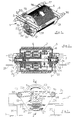
- the speed limiter shown in Figures 1 to 3, consists of a support 1 carried, by means of a cradle 2, by the frame 3 of the conveyor or the corridor dynamic storage.
- This support 1 comprises lateral beams 5 which support the brake drum 6.
- This brake drum 6 has a tire 7 made of adherent material, and it contains a braking mechanism 8 consisting of weights and a double planetary gear train 9 which achieves the rotational drive of these weights, at inside the drum.
- This drum and its braking mechanism are mounted on a central shaft 10 which is carried by the lateral beams 5 and in particular by arms which constitute said beams.
- This tree 10 is located mid-length of the beams 5.
- the median plane of these last is between tree 10 and the periphery drum 6 which is in contact with the load.
- the distance between the shaft 10 and the median plane of the beams 5 corresponds substantially to a third of the radius of the drum 6.
- the beams 5 are each divided into two arms 51 and 52.
- the arms 51 called the upstream arms, are longer that the arms 52; they wear the braking mechanism 1.
- the arms 52 called the downstream arms, retain the arms upstream.
- the shaft 10 is secured to the arms 51 by through the sockets 11 and 12 which constitute the lateral bearings of the drum 6.
- the socket 11 constitutes the fixed part of the trains epicycloidals 9. Indeed, it constitutes the planet carrier of the first planetary train.
- sockets 11 and 12 each have a housing 13 which allows them to fit together, without play, on a pin 14 associated with the shaft 10.
- These pins 14 are perpendicular to the shaft 10 and allow to immobilize and secure the sockets 11 and 12 relative to each other, in a way precise.
- the sockets 11 and 12 have, at their ends, locking means with their arms supports 51.
- Each socket 11, 12 has at its end a hexagonal outline for example, which fits into a similar outline arranged on the arms 51. This outline appears in figure 3. It immobilizes in a simple and effective way the sockets 11 and 12 relative to the arms 51.
- these parts with the exception of the central shaft, are made of plastic material mold.
- the arms 51 and 52 are separated by a articulation 15 which consists of a simple thinning of material and which allows movement arms 51 and 52, one relative to the other.
- rods 16 and 17 are slidably mounted in arms 51 and 52 respectively, so that allow retraction of one of their ends. They include between the arms, stops 18 and 19 in the shape of elephant legs for example and between the stops 19 and the arms, springs 20 which allow the ends to be overshadowed to facilitate mounting the device in its cradle and particular a cradle of the type shown Figures 10 to 12.
- the arms 51 and 52 each have gussets 21 and 22 which extend below their median plane. These gussets are arranged in a perpendicular plane to the axis of the speed limiter shaft 10.
- gussets 21 and 22 have a stop 23 which limits the range of motion of the arms 51 and 52 around the joint 15.
- An elastic organ 24 in the form of a helical spring tends to approximate gussets 21 and 22 and put them in contact with level of the stop 23.
- This first spring 24 has a resistance to elongation which is relatively low, of the order of 1 to 5 newtons / mm for example.
- This spring 24 has the function of keeping the drum 6 projecting in a direct assembly as shown in Figure 4 and to maintain a contact pressure between said drum and its drive vector that is to say the load consisting of a pallet or a crate in the case of direct mounting or the roller (s) intermediates in the case of indirect mounting.
- This spring 24 is arranged under the plane of the arms 51, 52, on the same side as the tree 10 but below of the last. It has a second organ elastic 25 in the form of a helical spring also, attached to the ends of gussets 21 and 22. We note that this spring 25 is positioned in the size of the outer casing of the drum 36, at its periphery, under the spring 24. The spring 24 is interposed between spring 25 and the shaft 10 of drum 6.
- the gussets 21 and 22 are shaped accordingly to allow this positioning of springs 24 and 25.
- the gusset 21 in particular, has a recess under the axis 10 of the drum 6, in particular under the hub 26 of the arm 51.
- the arm 51, which carries the hub 26 is longer than arm 52.
- Joint 15 is slightly offset from the passing vertical median plane by the axis of the shaft 10, a distance which is about a third of the radius of the drum 6.
- the second elastic member 25 has an action deferred with respect to spring 24. It is housed, at its ends, in orifices 27 of shapes oblong. These orifices 27 are inclined relative to to the axis of the spring 25 and converge at a point located under said spring.
- This spring 25 comes into action, that is to say that it is stressed by the gussets 21 and 22, when the arms 51 and 52 are misaligned and tilt relative to each other around the joint 15, placing said joint 15 below of the plane passing through the axes of the rods 16 and 17.
- This situation is caused by braking important of the drum 6, which braking causes, on the arms 51 which are integral with the planet carrier socket 11 a reaction that tends to make them spin in the same direction as the drum 6.
- the spring 25 remains inactive when the drum 6 goes from the inactive position to the active position in which it is on the one hand overshadowed by the load and, on the other hand, kept in contact with the latter by the spring 24.
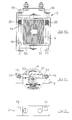
- Figure 4 shows the mounting of a device speed limiter in a corridor made up of rollers 30 arranged in a slope on the frame 3 to form an inclined plane on which a pallet 31 moves by simple gravity, with its load, not shown.
- This speed limiter device is carried by a cradle 2 which is integral with the frame 3 of the installation.
- the device is consisting of its arms 51, 52, separated by the joint 15. Under the arms 51 and 52 extend, the gussets 21 and 22 respectively. These gussets have, shown in their lower part extreme, the stop 23. They are constantly used by spring 24. Spring 25 acts on the gussets when the arms 51 and 52 tilt one relative to the other, around joint 15, under the effect braking or blocking the drum 6 which tends to cause the arms 51 to rotate.
- spring 25 has a deferred action. It does come into play eventually only after the drum is eclipsed under the effect of the passage of a load whose speed is such that it causes a significant braking reaction of the limiter.
- the arm 52 is secured to the cradle 2 by means its rod 17 which cooperates with a joint 32 of said cradle.
- the rod 16 of the arm 51 is simply placed on a support 33 of the cradle 2, so that move at will and in particular allow the tilting of said arm 51 around the joint 15 which separates it from the arm 52, when the drum 6 tends to train it in rotation.
- the arms 51 and 52 tilt upwards, positioning the joint 15 above the plane of their supports as shown in figure 3.
- the angle of the dihedral formed by the arms is greater than 180 ° on the side of the drum contact area 6.
- FIG. 5 represents an indirect mounting of the speed limiter device.
- This device is supported by a cradle 2, under a pair of rollers 30. Its drum 6 is automatically centered by compared to two successive rolls 30. These two rollers are slightly protruding from the plan of the other rollers, in the absence of pallets. They are generally mounted with a slight vertical clearance which allows to obtain this slight vertical offset of rollers in contact with the drum in relation to other rollers which are free.
- Rods 16 and 17 of the speed are simply placed in the cradle 2, on two supports 33 which are planar and parallel to the load circulation surface.
- the device limiter is partially free in a parallel plane to that of the plane in which the pallets move 31, so that it can be centered automatically by compared to the two rollers 30 with which the drum 6 is in contact.
- the cradle is positioned so as to maintain the end of the arm 52 and in particular the rod 17, at a distance d from a wall 34 which constitutes a kind of stop.
- This vertical wall 34 is part of the cradle 2; it is located at the end of the support 33 located on the left in the figure.
- the distance d is of the order of a few millimeters, three to ten approximately.
- Figure 7 schematically shows one of the ends of the elastic member 25 relative to the gussets 22 for example.
- the elastic member 25 in the inactive position, i.e. in the position which corresponds to FIG. 3, the elastic member 25 is free relative to its support gusset 22, and also relative to its gusset 21 not shown.
- Figure 8 shows the spring 25 in one any of the configurations in Figures 4 to 6.
- the arms 51 and 52 are in the same plane as joint 15.
- Spring 24 acts alone to maintain pressure between the drum and its training vector, that is to say the palette 31 or the rollers 30.
- the spring 25 is always inactive in this configuration, but it is ready to intervene.
- FIG. 9 represents the spring 25 activated by the gussets 21, 22, when, due to a speed important linear of the training vector, the drum 6, strongly braked, even blocked, drives its support arm 51 in a rotational movement which causes misalignment of both arms around the joint 15 and a spacing of said gussets.
- Spring 25 has elongation resistance more important than that of spring 24. This resistance can be 4 to 8 times that of the spring 24, chosen according to the loads, i.e. from 5 to 40 newtons / mm.
- Figure 6 shows another possibility indirect mounting of the speed limiter; the drum 6 is in contact with a single roller 30.
- the rods 16 and 17 arms 51 and 52 have their ends laid on supports 33 of the cradle 2.
- This cradle comprises a wall 35 on which the ends bear of the rod 16 of the arm 51 so as to maintain a contact and pressure between the drum 6 and its drive roller 30.
- the speed limiter and in particular the arm 52 retains a possibility of translation in direction reverse of the movement of the pallet 31, to allow, when the drum is strongly braked, the action of the spring 25.
- This implementation of the spring 25 increases the pressure between the drum 6 and the roller 30 and increase the adhesion.
- the spring 25 allows to control the grip and the limit to a certain pre-established threshold, to avoid any deterioration of the speed limiter device and especially its braking mechanism.
- a distance d which is available between the end of the arm 52 and the wall 34, to allow a limited translation of the device in the cradle 2. This distance d is around three to ten millimeters.
- Figure 10 shows a speed limiter positioned in a cradle 2.
- This cradle 2 is presented in the form of a strip of sheet metal folded so as to form an open frame on one side of the device and which is provided, on the other side, with a projecting part which allows it to be fixed offset to the frame of the installation.
- This cradle 2 has, as shown in the figures 11 and 12 of the orifices 36 which allow the passage rods 16 and 17 supporting the limiter device of speed.
- FIG. 3 Another embodiment of the cradle is shown in Figure 3 and partially in Figure 2; he includes side angles 37 provided with orifices 38 open at the top to allow removing the speed limiter device. These angles 37 are placed on sleepers 39 integral with the frame 3.
- the holes 38 have a length which is greater than the diameter of rods 16 and 17 for allow movement of the latter.
- Figure 13 shows a portion of the conveyor in a dynamic storage installation, consisting of a multitude of rollers 30 which form a plane tilted on which move, by simple gravity, the pallets 31.
- the limiter is not in direct contact with the rollers 30.
- the speed limiter drum 6 is in contact with a pair of rollers or rollers 40 which are themselves arranged under the rollers 30.
- rollers 40 are in contact with the same roller 30 and with the other rollers adjacent to this last.
- the rollers 40 provide a kind of coupling three rollers 30 located above the limiter of speed.
- Figure 14 shows the speed limiter in action during braking which is important and which activates the two springs 24 and 25.
- roller 40 in contact downstream with the drum 6 moves slightly, vertically. Its axis 41 is guided in slides 42 in the form of lights arranged laterally and vertically oriented.
- the rollers 40 are made of material which has a high coefficient of adhesion, such as polyurethane. These rollers 40 have a diameter which can be lower than that of the rollers 30.
- Figures 13 and 14 also show a roller or additional intermediate roller 43 located in downstream of the rollers 40.
- This roller 43 also serves as an organ coupling between the rollers located downstream of the speed limiter drum 6.
Landscapes
- Engineering & Computer Science (AREA)
- Mechanical Engineering (AREA)
- Rollers For Roller Conveyors For Transfer (AREA)
- Stacking Of Articles And Auxiliary Devices (AREA)
Claims (14)
- Geschwindigkeitsbegrenzer für Kästen oder Paletten, die fähig sind, sich durch Schwerkraft auf einer von Rollen oder Walzen gebildeten, geneigten Ebene zu bewegen, welcher Begrenzer vom Trommel- oder Walzentyp (6) ist, wobei die Trommel direkt oder indirekt mittels wenigstens einer Rolle (30) oder Walze der geneigten Ebene gegen die Last gedrückt wird, wobei der Drehbewegung dieser Trommel (6) unter der Wirkung ihres Antriebsvektors mittels eines auf die Geschwindigkeit ansprechenden Bremsmechanismus entgegenwirkt wird, wobei die Trommel (6) und der Mechanismus auf einer Welle (10) angebracht sind, die hinsichtlich der Richtung der Vorwärtsbewegung der Lasten quer verläuft und die von einem Halter gehalten wird, der mit dem Unterteil der geneigten Ebene fest verbunden ist, wobei der Halter dauernd derart elastisch beansprucht wird, um einen Kontakt und einen Druck zwischen der Trommel (6) und dem Antriebsvektor zu schaffen, dadurch gekennzeichnet, daß der Halter mit dem Unterteil mit einem gewissen Freiheitsgrad verbunden ist, um ihm eine Deformation durch eine Drehbewegung um eine Querachse in bezug auf die Lastbewegung zu erlauben, und daß der Begrenzer elastische Mittel aufweist, die eine erste Niveauzunahme des Drukkes infolge eines ersten Widerstandes gegen die Deformation des Halters aufbauen und die in Kombination mit der Drehbewegung des Halters bei einer starken Bremsung infolge eines zweiten Widerstandes gegen die größere Deformation dazu neigen, die Niveauzunahme des Druckes zwischen der Trommel (6) und ihrem Antriebsvektor zu vergrößern, um eine zweite Niveauzunahme der Haftung größer als die erste aufzubauen, die auf einen bestimmten Grenzwert begrenzt ist, um jede Störung insbesondere auf den Bremsmechanismus zu vermeiden.
- Geschwindigkeitsbegrenzer-Vorrichtung nach Anspruch 1 des Typs, der aus einem Halter besteht, der von zwei Trägern (5) gebildet ist, die seitlich beiderseits der Trommel angeordnet sind, welche Träger jeweils von zwei durch ein Gelenk (15) getrennten Armen (51, 52) gebildet sind: - einem stromaufwärtigen Tragarm (51) für die Welle (10) der Trommel (6), der sich zwischen den Stützmitteln am Unterteil und dem Gelenk erstreckt, und - einem stromabwärtigen Arm (52), der sich zwischen diesem letzteren und weiteren Stützmitteln am Unterteil erstreckt, welche Arme einen Dieder definieren, dessen Kante, die dem Gelenk (15) entspricht, parallel zur Welle (10) der Trommel verläuft, und seine Arme außerdem jeweils mit Eckstücken (21, 22) versehen sind, die in einer zur Welle (10) senkrechten Ebene angeordnet sind, welche Eckstücke einen Anschlag (23) tragen, der in Ruheposition den Arm leicht fehlausgerichet hält, wobei die Achse (15) über der durch ihre Enden gehenden Ebene positioniert wird, welche Eckstücke außerdem ein elastisches Organ tragen, das dauernd beansprucht wird, so daß ein Kontakt zwischen der Trommel (6) und ihrem Antriebsvektor aufgebaut ist, dadurch gekennzeichnet, daß sie einerseits Mittel zur teilweisen Verbindung zwischen diesen Armen (51, 52) und den Stützmitteln am Unterteil aufweist, um die Bewegung der Arme zu organisieren, welche Bewegung durch wenigstens zwei an den Eckstücken angebrachte, elastische Organe gehindert wird: - durch ein erstes elastisches Organ (24), dessen Streckfestigkeit gering ist, um das Verschwinden der Trommel bei Durchgang einer Last zu gestatten und um die Trommel (6) unter schwachem Druck mit ihrem Antriebsvektor in Kontakt zu halten - und ein zweites elastisches Organ (25), dessen Streckfestigkeit größer ist, das auf den Eckstücken positioniert ist, so daß es auf die Eckstücke einwirkt, um dazu zu neigen, die Arme (51 und 52) ausgerichtet zu halten, insbesondere wenn unter der Wirkung einer starken Bremsung der Trommel (6) der Arm (51), angetrieben durch die Trommel (6), um das Gelenk kippt.
- Geschwindigkeitsbegrenzer nach Anspruch 2, dadurch gekennzeichnet, daß die Eckstücke (21, 22) Mittel in Form von länglichen Löchern (27) aufweisen, um einen für das zweite elastische Organ (25) ausreichenden Spielraum zu bieten, um ihm zu gestatten, inaktiv zu bleiben, wenn die Trommel (6) von der inaktiven Position zu der Position übergeht, in der sie einerseits durch die Last verschwunden ist und andererseits durch das erste elastische Organ (24) mit dieser letzteren in Kontakt gehalten wird.
- Geschwindigkeitsbegrenzer nach einem der Ansprüche 2 oder 3, dadurch gekennzeichnet, daß er ein erstes elastisches Organ (24) in Form einer Wendelfeder aufweist, deren Streckfestigkeit von der Größenordnung von 1 bis 5 N/mm ist.
- Geschwindigkeitsbegrenzer nach einem der Ansprüche 2 bis 4, dadurch gekennzeichnet, daß das zweite elastische Organ (25) in Form einer Wendelfeder eine Streckfestigkeit zwischen 5 und 40 N/mm aufweist.
- Geschwindigkeitsbegrenzer nach einem der Ansprüche 2 bis 5, dadurch gekennzeichnet, daß die Arme (51, 52) an ihrem Ende quer verlaufende Stangen (16, 17) aufweisen, die in einem Fuß (2) positioniert sind, der am Unterteil (3) befestigt ist, welcher Fuß Öffnungen (36, 38) aufweist, deren Abmessungen größer als der Durchmesser der Stangen sind, so daß wenigstens einer dieser Stangen ein Bewegungsspielraum zugeteilt wird, der ihr gestattet, sich kontrolliert in einer zur Ebene der Verschiebung der Last parallelen Ebene zu verschieben.
- Geschwindigkeitsbegrenzer nach Anspruch 6, dadurch gekennzeichnet, daß die Fenster (36) des Fußes eine Höhe aufweisen, die größer als der Durchmesser der Stangen (16, 17) ist, die insbesondere der Stange des stromaufwärtigen Armes (51) einen Bewegungsspielraum in Richtung der Last gestattet.
- Geschwindigkeitsbegrenzer nach Anspruch 2, dadurch gekennzeichnet, daß die Welle (10) der Trommel (6) und des Bremsmechanismus Mittel zur festen Verbindung der beiden stromaufwärtigen Arme (51) miteinander aufweisen.
- Geschwindigkeitsbegrenzer nach Anspruch 8, dadurch gekennzeichnet, daß die Welle (10) der Trommel zwei Stifte (14) oder Keile aufweist, die jeweils mit einer Aufnahme (13) zusammenarbeiten, die in der Hülse (11, 12) der Seitenlager angebracht ist, wobei jede Hülse mit einem der stromaufwärtigen Arme (51) durch eine in Rotation verriegelte Anordnung zusammenarbeitet.
- Geschwindigkeitsbegrenzer nach einem der Ansprüche 2 bis 9, dadurch gekennzeichnet, daß die Stangen (16, 17) der Träger (5) parallel zur Welle (10) beweglich sind, die jeweils zwei Anschläge (18, 19) zwischen den Trägern und eine Feder (20) zwischen einem der Anschläge (19) und dem einen Träger aufweisen, um das Verschwinden eines der Enden der Stangen (16, 17) zu gestatten, um das Anbringen des Begrenzers in seinem Tragfuß zu erleichtern.
- Geschwindigkeitsbegrenzer nach Anspruch 10, dadurch gekennzeichnet, daß der Fuß (2) aus einem Blechstreifen besteht, der so gebogen ist, daß er einen auf der einen Seite des Begrenzers offenen Rahmen bildet und entgegengesetzt zur offenen Seite mit einem vorstehenden Teil versehen ist, der die versetzte Befestigung des Rahmens am Unterteil der geneigten Ebene gestattet.
- Dynamische Lagerhaltungsanlage, die mit wenigstens einem Geschwindigkeitsbegrenzer nach einem der Ansprüche 1 bis 11 versehen ist, dadurch gekennzeichnet, daß sie unter den Rollen (30), die die geneigte Ebene bilden, Zwischenwalzen oder -rollen (40) aufweisen, die einerseits mit den Rollen (30) und andererseits mit der Trommel (6) des Begrenzers in Kontakt stehen, wenn sich dieser letztere im normalen Bremsbereich befindet.
- Dynamische Lagerhaltungsanlage nach Anspruch 12, dadurch gekennzeichnet, daß die Zwischenwalze (40), die stromabwärts mit der Trommel (6) des Geschwindigkeitsbegrenzers in Kontakt steht, eine Achse (41) aufweist, die in vertikal orientierten, seitlichen Schlitzen (42) geführt ist.
- Dynamische Lagerhaltungsanlage nach einem der Ansprüche 12 und 13, dadurch gekennzeichnet, daß sie wenigstens eine stromabwärts der Walzen (40) angeordnete Walze oder Rolle (43) aufweist, die ein Kupplungsorgan zwischen den beiden Rollen (30) bildet, die sich stromabwärts der Trommel (6) des Geschwindigkeitsbegrenzers befindet.
Applications Claiming Priority (3)
| Application Number | Priority Date | Filing Date | Title |
|---|---|---|---|
| FR9414681A FR2727674A1 (fr) | 1994-12-02 | 1994-12-02 | Limiteur de vitesse pour caisses ou palettes diversement chargees, susceptibles de se deplacer par gravite sur un plan incline forme de rouleaux ou galets |
| FR9414681 | 1994-12-02 | ||
| PCT/FR1995/001588 WO1996016883A1 (fr) | 1994-12-02 | 1995-12-01 | Limiteur de vitesse pour caisses ou palettes diversement chargees, susceptibles de se deplacer par gravite sur un plan incline forme de rouleaux ou galets |
Publications (2)
| Publication Number | Publication Date |
|---|---|
| EP0793609A1 EP0793609A1 (de) | 1997-09-10 |
| EP0793609B1 true EP0793609B1 (de) | 1998-08-26 |
Family
ID=9469541
Family Applications (1)
| Application Number | Title | Priority Date | Filing Date |
|---|---|---|---|
| EP95941753A Expired - Lifetime EP0793609B1 (de) | 1994-12-02 | 1995-12-01 | Geschwindigkeitsbegrenzer für kisten oder paletten, die unterschiedlich beladen sind und durch schwerkraft auf einer geneigten, mit rollen versehenen, ebene bewegt werden |
Country Status (8)
| Country | Link |
|---|---|
| US (1) | US6082517A (de) |
| EP (1) | EP0793609B1 (de) |
| AT (1) | ATE170154T1 (de) |
| AU (1) | AU4306696A (de) |
| DE (2) | DE69504368T2 (de) |
| ES (1) | ES2122709T3 (de) |
| FR (1) | FR2727674A1 (de) |
| WO (1) | WO1996016883A1 (de) |
Families Citing this family (2)
| Publication number | Priority date | Publication date | Assignee | Title |
|---|---|---|---|---|
| DE29621925U1 (de) * | 1996-12-17 | 1997-02-20 | Nedcon Magazijninrichting B.V., Doetinchem | Bremsrolle, insbesondere zum Einbau in eine geneigte Rollenbahn |
| WO2000026122A1 (fr) * | 1998-11-03 | 2000-05-11 | Sipa Roller | Dispositif limiteur de vitesse pour tous types de palettes susceptibles de se deplacer par gravite dans un couloir de stockage dynamique |
Family Cites Families (9)
| Publication number | Priority date | Publication date | Assignee | Title |
|---|---|---|---|---|
| US1761199A (en) * | 1926-09-18 | 1930-06-03 | Libbey Owens Glass Co | Sheet-glass-handling apparatus |
| US1728538A (en) * | 1928-06-25 | 1929-09-17 | American Bicheroux Company | Speed-changing mechanism for glass sheets |
| US2236029A (en) * | 1938-07-11 | 1941-03-25 | Standard Conveyor Co | Roller conveyer |
| US3737022A (en) * | 1972-04-14 | 1973-06-05 | Western Gear Corp | Rapid retracting torque activated drive roller unit for conveyor systems |
| US3958684A (en) * | 1974-08-07 | 1976-05-25 | A W & H Manufacturing Co., Inc. | Accumulating conveyor |
| FR2627169B1 (fr) * | 1988-02-17 | 1992-07-31 | Sipa Sa | Support de frein regulateur de vitesse en particulier pour un convoyeur a rouleaux |
| EP0443060B1 (de) * | 1990-02-21 | 1992-12-02 | Bavaria Cargo Technologie Gmbh | Antriebsrolleneinheit |
| US5086903A (en) * | 1991-04-08 | 1992-02-11 | Interrolll Holding Ag | Tandem brake roller system |
| DE4336978C2 (de) * | 1993-10-29 | 1995-08-24 | Elektro Metall Exp Gmbh | Antriebseinheit, insbesondere für eine Verladeeinrichtung in einem Flugzeug |
-
1994
- 1994-12-02 FR FR9414681A patent/FR2727674A1/fr active Granted
-
1995
- 1995-12-01 US US08/849,077 patent/US6082517A/en not_active Expired - Lifetime
- 1995-12-01 ES ES95941753T patent/ES2122709T3/es not_active Expired - Lifetime
- 1995-12-01 AU AU43066/96A patent/AU4306696A/en not_active Abandoned
- 1995-12-01 DE DE69504368T patent/DE69504368T2/de not_active Expired - Lifetime
- 1995-12-01 DE DE0793609T patent/DE793609T1/de active Pending
- 1995-12-01 EP EP95941753A patent/EP0793609B1/de not_active Expired - Lifetime
- 1995-12-01 AT AT95941753T patent/ATE170154T1/de not_active IP Right Cessation
- 1995-12-01 WO PCT/FR1995/001588 patent/WO1996016883A1/fr not_active Ceased
Also Published As
| Publication number | Publication date |
|---|---|
| ES2122709T3 (es) | 1998-12-16 |
| DE793609T1 (de) | 1998-02-19 |
| WO1996016883A1 (fr) | 1996-06-06 |
| US6082517A (en) | 2000-07-04 |
| FR2727674A1 (fr) | 1996-06-07 |
| DE69504368D1 (de) | 1998-10-01 |
| DE69504368T2 (de) | 1999-04-29 |
| EP0793609A1 (de) | 1997-09-10 |
| AU4306696A (en) | 1996-06-19 |
| ATE170154T1 (de) | 1998-09-15 |
| FR2727674B1 (de) | 1997-02-28 |
Similar Documents
| Publication | Publication Date | Title |
|---|---|---|
| FR2759340A1 (fr) | Systeme de guidage le long d'au moins un rail au sol pour un essieu d'un vehicule routier | |
| EP1278984B1 (de) | Ein motorgetriebener wagen fähig zur bewegung in einem zylindrischen stollen | |
| EP1914193B1 (de) | Scherenhebebühne | |
| EP0062370B1 (de) | Automatisches Führungssystem für ein mit Reifen ausgerüstetes Fahrzeug | |
| CA1233343A (fr) | Mecanisme de transformation d'un mouvement | |
| FR2860506A1 (fr) | Transporteur du type a chariot entraine par friction | |
| WO1988008802A1 (fr) | Dispositif de guidage et de sustentation d'un vehicule ferroviaire | |
| FR2531055A1 (fr) | Grue de levage | |
| FR2755678A1 (fr) | Dispositif de manutention de produits | |
| EP0793609A1 (de) | Geschwindigkeitsbegrenzer für kisten oder paletten, die unterschiedlich beladen sind und durch schwerkraft auf einer geneigten, mit rollen versehenen, ebene bewegt werden | |
| FR2927843A1 (fr) | Dispositif a roue pivotant comportant des moyens d'indexation de la roue dans une position determinee | |
| EP0712771B1 (de) | Automatische Blockiervorrichtung von walzenförmigen Teilen und Wagen mit solch einer Vorrichtung | |
| FR2645399A1 (fr) | Dispositif de chargement et de dechargement de balles cylindriques de paille ou de fourrage | |
| EP0508841A1 (de) | Scheibenwischerarm, insbesondere für Hochgeschwindigkeitsfahrzeuge | |
| FR2525547A1 (fr) | Dispositif de roulement pour un chariot transporteur deplace manuellement | |
| EP0757132B9 (de) | Brückenteil, insbesondere zur Überwindung von Gräben durch Fahrzeuge und System zum transportieren und ablegen von solchen Brückenteilen | |
| FR2540207A1 (fr) | Systeme de support et d'amortissement des mouvements d'une piece ou d'une machine | |
| EP3521533B1 (de) | Abdeckung für eine werkstattgrube | |
| CH399309A (fr) | Transporteur | |
| EP1792758A1 (de) | Weicher Anschlag für die Aufhängung eines Fahrzeugs | |
| EP1849720A1 (de) | Mobile vertikale Speichervorrichtung | |
| FR2593477A1 (fr) | Convoyeur a bande | |
| FR3139519A1 (fr) | Dispositif d’arrimage de charges, notamment de balles de fourrage, sur un véhicule de transport de charges, et véhicule de transport de charges comprenant au moins un tel dispositif d’arrimage | |
| FR2690124A1 (fr) | Train de roulage rétractable pour véhicule à sustentation sans contact. | |
| CH690548A5 (fr) | Dispositif de renvoi d'une bande de matériau. |
Legal Events
| Date | Code | Title | Description |
|---|---|---|---|
| PUAI | Public reference made under article 153(3) epc to a published international application that has entered the european phase |
Free format text: ORIGINAL CODE: 0009012 |
|
| 17P | Request for examination filed |
Effective date: 19970702 |
|
| AK | Designated contracting states |
Kind code of ref document: A1 Designated state(s): AT BE CH DE DK ES FR GB GR IE IT LI LU MC NL PT SE |
|
| GBC | Gb: translation of claims filed (gb section 78(7)/1977) | ||
| GRAG | Despatch of communication of intention to grant |
Free format text: ORIGINAL CODE: EPIDOS AGRA |
|
| 17Q | First examination report despatched |
Effective date: 19971217 |
|
| GRAG | Despatch of communication of intention to grant |
Free format text: ORIGINAL CODE: EPIDOS AGRA |
|
| DET | De: translation of patent claims | ||
| GRAG | Despatch of communication of intention to grant |
Free format text: ORIGINAL CODE: EPIDOS AGRA |
|
| GRAH | Despatch of communication of intention to grant a patent |
Free format text: ORIGINAL CODE: EPIDOS IGRA |
|
| GRAH | Despatch of communication of intention to grant a patent |
Free format text: ORIGINAL CODE: EPIDOS IGRA |
|
| GRAA | (expected) grant |
Free format text: ORIGINAL CODE: 0009210 |
|
| AK | Designated contracting states |
Kind code of ref document: B1 Designated state(s): AT BE CH DE DK ES FR GB GR IE IT LI LU MC NL PT SE |
|
| PG25 | Lapsed in a contracting state [announced via postgrant information from national office to epo] |
Ref country code: NL Free format text: LAPSE BECAUSE OF FAILURE TO SUBMIT A TRANSLATION OF THE DESCRIPTION OR TO PAY THE FEE WITHIN THE PRESCRIBED TIME-LIMIT Effective date: 19980826 Ref country code: GR Free format text: LAPSE BECAUSE OF NON-PAYMENT OF DUE FEES Effective date: 19980826 Ref country code: AT Free format text: LAPSE BECAUSE OF FAILURE TO SUBMIT A TRANSLATION OF THE DESCRIPTION OR TO PAY THE FEE WITHIN THE PRESCRIBED TIME-LIMIT Effective date: 19980826 |
|
| REF | Corresponds to: |
Ref document number: 170154 Country of ref document: AT Date of ref document: 19980915 Kind code of ref document: T |
|
| REG | Reference to a national code |
Ref country code: CH Ref legal event code: EP |
|
| REF | Corresponds to: |
Ref document number: 69504368 Country of ref document: DE Date of ref document: 19981001 |
|
| GBT | Gb: translation of ep patent filed (gb section 77(6)(a)/1977) |
Effective date: 19981013 |
|
| REG | Reference to a national code |
Ref country code: IE Ref legal event code: FG4D Free format text: FRENCH |
|
| PG25 | Lapsed in a contracting state [announced via postgrant information from national office to epo] |
Ref country code: SE Free format text: LAPSE BECAUSE OF FAILURE TO SUBMIT A TRANSLATION OF THE DESCRIPTION OR TO PAY THE FEE WITHIN THE PRESCRIBED TIME-LIMIT Effective date: 19981126 Ref country code: PT Free format text: LAPSE BECAUSE OF FAILURE TO SUBMIT A TRANSLATION OF THE DESCRIPTION OR TO PAY THE FEE WITHIN THE PRESCRIBED TIME-LIMIT Effective date: 19981126 Ref country code: DK Free format text: LAPSE BECAUSE OF FAILURE TO SUBMIT A TRANSLATION OF THE DESCRIPTION OR TO PAY THE FEE WITHIN THE PRESCRIBED TIME-LIMIT Effective date: 19981126 |
|
| PG25 | Lapsed in a contracting state [announced via postgrant information from national office to epo] |
Ref country code: LU Free format text: LAPSE BECAUSE OF NON-PAYMENT OF DUE FEES Effective date: 19981201 |
|
| REG | Reference to a national code |
Ref country code: ES Ref legal event code: FG2A Ref document number: 2122709 Country of ref document: ES Kind code of ref document: T3 |
|
| NLV1 | Nl: lapsed or annulled due to failure to fulfill the requirements of art. 29p and 29m of the patents act | ||
| PG25 | Lapsed in a contracting state [announced via postgrant information from national office to epo] |
Ref country code: IE Free format text: LAPSE BECAUSE OF NON-PAYMENT OF DUE FEES Effective date: 19990504 |
|
| PG25 | Lapsed in a contracting state [announced via postgrant information from national office to epo] |
Ref country code: MC Free format text: LAPSE BECAUSE OF NON-PAYMENT OF DUE FEES Effective date: 19990630 |
|
| REG | Reference to a national code |
Ref country code: IE Ref legal event code: FD4D |
|
| PLBE | No opposition filed within time limit |
Free format text: ORIGINAL CODE: 0009261 |
|
| STAA | Information on the status of an ep patent application or granted ep patent |
Free format text: STATUS: NO OPPOSITION FILED WITHIN TIME LIMIT |
|
| 26N | No opposition filed | ||
| PG25 | Lapsed in a contracting state [announced via postgrant information from national office to epo] |
Ref country code: LI Free format text: LAPSE BECAUSE OF NON-PAYMENT OF DUE FEES Effective date: 19991231 Ref country code: CH Free format text: LAPSE BECAUSE OF NON-PAYMENT OF DUE FEES Effective date: 19991231 |
|
| PGFP | Annual fee paid to national office [announced via postgrant information from national office to epo] |
Ref country code: BE Payment date: 20011213 Year of fee payment: 7 |
|
| REG | Reference to a national code |
Ref country code: GB Ref legal event code: IF02 |
|
| PG25 | Lapsed in a contracting state [announced via postgrant information from national office to epo] |
Ref country code: BE Free format text: LAPSE BECAUSE OF NON-PAYMENT OF DUE FEES Effective date: 20021231 |
|
| BERE | Be: lapsed |
Owner name: *SIPA ROLLER Effective date: 20021231 |
|
| REG | Reference to a national code |
Ref country code: ES Ref legal event code: PC2A |
|
| REG | Reference to a national code |
Ref country code: GB Ref legal event code: 732E |
|
| REG | Reference to a national code |
Ref country code: FR Ref legal event code: TP Ref country code: FR Ref legal event code: CJ Ref country code: FR Ref legal event code: CD |
|
| REG | Reference to a national code |
Ref country code: FR Ref legal event code: TP |
|
| PGFP | Annual fee paid to national office [announced via postgrant information from national office to epo] |
Ref country code: FR Payment date: 20110107 Year of fee payment: 16 |
|
| PGFP | Annual fee paid to national office [announced via postgrant information from national office to epo] |
Ref country code: GB Payment date: 20101221 Year of fee payment: 16 |
|
| PGFP | Annual fee paid to national office [announced via postgrant information from national office to epo] |
Ref country code: IT Payment date: 20101229 Year of fee payment: 16 Ref country code: DE Payment date: 20101220 Year of fee payment: 16 |
|
| PGFP | Annual fee paid to national office [announced via postgrant information from national office to epo] |
Ref country code: ES Payment date: 20101222 Year of fee payment: 16 |
|
| GBPC | Gb: european patent ceased through non-payment of renewal fee |
Effective date: 20111201 |
|
| REG | Reference to a national code |
Ref country code: FR Ref legal event code: ST Effective date: 20120831 |
|
| REG | Reference to a national code |
Ref country code: DE Ref legal event code: R119 Ref document number: 69504368 Country of ref document: DE Effective date: 20120703 |
|
| PG25 | Lapsed in a contracting state [announced via postgrant information from national office to epo] |
Ref country code: GB Free format text: LAPSE BECAUSE OF NON-PAYMENT OF DUE FEES Effective date: 20111201 Ref country code: DE Free format text: LAPSE BECAUSE OF NON-PAYMENT OF DUE FEES Effective date: 20120703 |
|
| PG25 | Lapsed in a contracting state [announced via postgrant information from national office to epo] |
Ref country code: IT Free format text: LAPSE BECAUSE OF NON-PAYMENT OF DUE FEES Effective date: 20111201 |
|
| PG25 | Lapsed in a contracting state [announced via postgrant information from national office to epo] |
Ref country code: FR Free format text: LAPSE BECAUSE OF NON-PAYMENT OF DUE FEES Effective date: 20120102 |
|
| REG | Reference to a national code |
Ref country code: ES Ref legal event code: FD2A Effective date: 20130703 |
|
| PG25 | Lapsed in a contracting state [announced via postgrant information from national office to epo] |
Ref country code: ES Free format text: LAPSE BECAUSE OF NON-PAYMENT OF DUE FEES Effective date: 20111202 |