EP0793764B1 - Schraubverbindung für bohrgestängeelementen zum schlagbohren - Google Patents
Schraubverbindung für bohrgestängeelementen zum schlagbohren Download PDFInfo
- Publication number
- EP0793764B1 EP0793764B1 EP95938689A EP95938689A EP0793764B1 EP 0793764 B1 EP0793764 B1 EP 0793764B1 EP 95938689 A EP95938689 A EP 95938689A EP 95938689 A EP95938689 A EP 95938689A EP 0793764 B1 EP0793764 B1 EP 0793764B1
- Authority
- EP
- European Patent Office
- Prior art keywords
- drill string
- contact surface
- wear resistant
- thread coupling
- thread
- Prior art date
- Legal status (The legal status is an assumption and is not a legal conclusion. Google has not performed a legal analysis and makes no representation as to the accuracy of the status listed.)
- Expired - Lifetime
Links
- 230000008878 coupling Effects 0.000 title claims abstract description 14
- 238000010168 coupling process Methods 0.000 title claims abstract description 14
- 238000005859 coupling reaction Methods 0.000 title claims abstract description 14
- 238000005553 drilling Methods 0.000 title claims abstract description 5
- 239000000463 material Substances 0.000 claims abstract description 18
- 229910001347 Stellite Inorganic materials 0.000 claims abstract description 5
- AHICWQREWHDHHF-UHFFFAOYSA-N chromium;cobalt;iron;manganese;methane;molybdenum;nickel;silicon;tungsten Chemical compound C.[Si].[Cr].[Mn].[Fe].[Co].[Ni].[Mo].[W] AHICWQREWHDHHF-UHFFFAOYSA-N 0.000 claims abstract description 5
- 238000003466 welding Methods 0.000 claims abstract description 5
- 239000002184 metal Substances 0.000 claims description 2
- 238000005476 soldering Methods 0.000 claims description 2
- 238000004519 manufacturing process Methods 0.000 description 3
- 230000007423 decrease Effects 0.000 description 1
Images
Classifications
-
- E—FIXED CONSTRUCTIONS
- E21—EARTH OR ROCK DRILLING; MINING
- E21B—EARTH OR ROCK DRILLING; OBTAINING OIL, GAS, WATER, SOLUBLE OR MELTABLE MATERIALS OR A SLURRY OF MINERALS FROM WELLS
- E21B17/00—Drilling rods or pipes; Flexible drill strings; Kellies; Drill collars; Sucker rods; Cables; Casings; Tubings
- E21B17/02—Couplings; joints
- E21B17/04—Couplings; joints between rod or the like and bit or between rod and rod or the like
- E21B17/042—Threaded
- E21B17/0426—Threaded with a threaded cylindrical portion, e.g. for percussion rods
Definitions
- the present invention relates to a thread coupling for drill string elements for percussive drilling, according to the preamble of claim 1.
- Such a device is described in SE-B-50/356.
- the present invention aims at increasing the service life of the drill string elements through lining a contact surface on one of the drill string elements or the free end of the other drill string element with a wear resistant additional material, e.g. a stellite, applied by means of welding or soldering. It is also an aim of the present invention to obtain the increase of the service life at a substantially lower cost
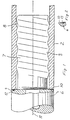
- fig 1 shows a first embodiment of a thread coupling according to the invention, partly in section.
- Fig 2 shows a part of a thread coupling according to a second embodiment of the invention.
- the embodiment of the invention shown in fig 1 comprises a first drill string element 2 and a second drill string element 6.
- the first drill string element 2 is provided with an internal thread 3 and a free end 4.
- the second drill sting element 6 is provided with a spigot 7 having an external thread 8.
- At the inner end of the spigot the second drill string element is provided with a contact surface 10.
- the contact surface 10 and the free end 4 are situated in a plane being perpendicular to the longitudinal axis 11 of the thread coupling and are intended for abutting each other.
- the annular contact surface 10 is provided with a lining of a wear resistant additional material. It has turned out to be suitable to choose a stellite which makes it possible to keep the porosity low. An example of such a material is stellite 6.
- the depth of the lining should be 0.5-5 mm. It has turned out to be particularly advantageous to apply the wear resistant material by means of plasma welding.
- Fig 2 shows a part of a modified embodiment of the thread coupling.
- the wear resistant material is here made as a ring 13 which has been soldered to the contact surface 10.
- a hard metal e.g. a carbide containing 5-20% Co, is chosen.
- the embodiment is in other respects made as in the example in fig 1.
Landscapes
- Engineering & Computer Science (AREA)
- Life Sciences & Earth Sciences (AREA)
- Geology (AREA)
- Mining & Mineral Resources (AREA)
- Mechanical Engineering (AREA)
- Physics & Mathematics (AREA)
- Environmental & Geological Engineering (AREA)
- Fluid Mechanics (AREA)
- General Life Sciences & Earth Sciences (AREA)
- Geochemistry & Mineralogy (AREA)
- Earth Drilling (AREA)
- Drilling Tools (AREA)
Claims (6)
- Schraubverbindung zum Schlagbohren mit einem ersten Bohrgestängeelement (2) mit einem Innengewinde (3) an einem freien Ende (4) und einem zweiten Bohrgestängeelement (6) mit einem Zapfen (7) mit einem Außengewinde (8) für das Zusammenwirken mit dem Innengewinde (3) am ersten Bohrgestängeelement (2), wobei das zweite Bohrgestängeelement (6) mit einer Berührungsfläche (10) für das Zusammenwirken mit dem freien Ende (4) des ersten Bohrgestängeelementes (2) versehen ist, dadurch gekennzeichnet, daß die Berührungsfläche (10) oder das freie Ende (4) mit einer Verkleidung (12) aus einem verschleißfesten, zusätzlichen Material versehen ist, das durch Löten oder Schweißen aufgebracht wurde, und daß das verschleißfeste, zusätzliche Material 50 - 100% der Berührungsfläche (10) bedeckt und eine Tiefe von 0,5 - 5 mm hat
- Schraubverbindung gemäß Anspruch 1, dadurch gekennzeichnet, daß das verschleißfeste Material Stellit ist.
- Schraubverbindung gemäß Anspruch 1 oder 2, dadurch gekennzeichnet, daß das verschleißfeste Material durch Plasmaschweißen aufgebracht wurde.
- Schraubverbindung gemäß Anspruch 1 oder 2, dadurch gekennzeichnet, daß das verschleißfeste Material ein Ring (13) ist, der auf die Berührungsfläche (19) aufgelötet wurde.
- Schraubverbindung gemäß Anspruch 4, dadurch gekennzeichnet, daß der Ring aus Hartmetall mit 5 - 20% Co besteht.
- Schraubverbindung gemäß irgendeinem der vorhergehenden Ansprüche, dadurch gekennzeichnet, daß das verschleißfeste Material 50 - 90% der Berührungsfläche (10) bedeckt und einen maximalen Durchmesser besitzt, der kleiner ist als der Außendurchmesser der Berührungsfläche.
Applications Claiming Priority (3)
| Application Number | Priority Date | Filing Date | Title |
|---|---|---|---|
| SE9404051A SE506695C2 (sv) | 1994-11-23 | 1994-11-23 | Gängskarv för slående borrning |
| SE9404051 | 1994-11-23 | ||
| PCT/SE1995/001381 WO1996016246A1 (en) | 1994-11-23 | 1995-11-21 | Thread coupling for drill string elements for percussive drilling |
Publications (2)
| Publication Number | Publication Date |
|---|---|
| EP0793764A1 EP0793764A1 (de) | 1997-09-10 |
| EP0793764B1 true EP0793764B1 (de) | 2000-03-15 |
Family
ID=20396077
Family Applications (1)
| Application Number | Title | Priority Date | Filing Date |
|---|---|---|---|
| EP95938689A Expired - Lifetime EP0793764B1 (de) | 1994-11-23 | 1995-11-21 | Schraubverbindung für bohrgestängeelementen zum schlagbohren |
Country Status (11)
| Country | Link |
|---|---|
| US (1) | US5785360A (de) |
| EP (1) | EP0793764B1 (de) |
| AT (1) | ATE190694T1 (de) |
| AU (1) | AU688998B2 (de) |
| CA (1) | CA2205902C (de) |
| DE (1) | DE69515686T2 (de) |
| ES (1) | ES2145309T3 (de) |
| FI (1) | FI107825B (de) |
| RU (1) | RU2155852C2 (de) |
| SE (1) | SE506695C2 (de) |
| WO (1) | WO1996016246A1 (de) |
Families Citing this family (10)
| Publication number | Priority date | Publication date | Assignee | Title |
|---|---|---|---|---|
| SE515518C2 (sv) * | 1998-09-28 | 2001-08-20 | Uniroc Ab | Gängförband för borrsträng för slående bergborrning |
| SE0000701L (sv) * | 2000-03-02 | 2001-06-25 | Sandvik Ab | Gängförband och bergborrelement för slående borrning |
| SE522221C2 (sv) * | 2001-10-12 | 2004-01-27 | Sandvik Ab | Gängförband för slående bergborrning |
| SE520077C2 (sv) * | 2002-06-27 | 2003-05-20 | Sandvik Ab | Handel, borrkrona och gängförband för slående bergborrning |
| SE525431C2 (sv) * | 2003-02-24 | 2005-02-22 | Sandvik Ab | Handel för slående borrning |
| JP4954542B2 (ja) * | 2005-12-09 | 2012-06-20 | 三菱マテリアル株式会社 | 掘削ロッド、掘削ビット及び掘削工具 |
| SE531459C2 (sv) * | 2006-05-17 | 2009-04-14 | Sandvik Intellectual Property | Hondel samt förfarande för tillverkning av hondelar |
| SE0702638L (sv) * | 2007-11-21 | 2008-07-29 | Sandvik Intellectual Property | Slagborrkrona för bergborrning och förfarande för tillverkning av en dylik borrkrona |
| SE534450C2 (sv) | 2009-07-01 | 2011-08-30 | Atlas Copco Rock Drills Ab | Anordning och metod för att skydda en bergborrmaskin mot korrosionsangrepp |
| SE535814C2 (sv) | 2011-05-20 | 2013-01-02 | Atlas Copco Secoroc Ab | Gänganordning, gängförband samt borrsträngskomponent för slående bergborrning |
Family Cites Families (10)
| Publication number | Priority date | Publication date | Assignee | Title |
|---|---|---|---|---|
| US2052019A (en) * | 1931-12-26 | 1936-08-25 | Timken Roller Bearing Co | Separable drill bit |
| FR984664A (fr) * | 1948-05-15 | 1951-07-09 | Hughes Tool Co | Raccord à éléments filetés applicable notamment aux équipements de forage des puits |
| US2772899A (en) * | 1948-05-15 | 1956-12-04 | Hughes Tool Co | Threaded oil well drill stem connection with the threads having included crest angleof 90 degrees |
| US3489445A (en) * | 1967-10-18 | 1970-01-13 | Archer W Kammerer Jr | Threaded sucker rod joint |
| SE469602B (sv) * | 1985-04-04 | 1993-08-02 | Sandvik Ab | Skarvgaenga foer slagborrning |
| SE8600199L (sv) * | 1986-01-17 | 1987-07-18 | Loevab Loef Och Oestlund Ab | Borrverktyg |
| SU1432183A1 (ru) * | 1986-01-31 | 1988-10-23 | Ф.М. Толстихин | Устройство дл соединени штанг снар да ударного бурени |
| SU1550078A1 (ru) * | 1987-12-14 | 1990-03-15 | Специальное Конструкторское Бюро Всесоюзного Промышленного Объединения "Союзгеотехника" | Резьбовое соединение труб |
| SE469603B (sv) * | 1988-07-08 | 1993-08-02 | Sandvik Ab | Gaengfoerband |
| SE501356C2 (sv) * | 1993-07-02 | 1995-01-23 | Uniroc Ab | Gängskarv för borrsträngselement för slående borrning |
-
1994
- 1994-11-23 SE SE9404051A patent/SE506695C2/sv not_active IP Right Cessation
-
1995
- 1995-11-21 EP EP95938689A patent/EP0793764B1/de not_active Expired - Lifetime
- 1995-11-21 AU AU39972/95A patent/AU688998B2/en not_active Ceased
- 1995-11-21 RU RU97110158/03A patent/RU2155852C2/ru not_active IP Right Cessation
- 1995-11-21 DE DE69515686T patent/DE69515686T2/de not_active Expired - Fee Related
- 1995-11-21 WO PCT/SE1995/001381 patent/WO1996016246A1/en not_active Ceased
- 1995-11-21 AT AT95938689T patent/ATE190694T1/de not_active IP Right Cessation
- 1995-11-21 CA CA002205902A patent/CA2205902C/en not_active Expired - Fee Related
- 1995-11-21 ES ES95938689T patent/ES2145309T3/es not_active Expired - Lifetime
- 1995-11-21 US US08/849,322 patent/US5785360A/en not_active Expired - Fee Related
-
1997
- 1997-05-22 FI FI972183A patent/FI107825B/fi not_active IP Right Cessation
Also Published As
| Publication number | Publication date |
|---|---|
| DE69515686T2 (de) | 2000-11-23 |
| ATE190694T1 (de) | 2000-04-15 |
| EP0793764A1 (de) | 1997-09-10 |
| WO1996016246A1 (en) | 1996-05-30 |
| RU2155852C2 (ru) | 2000-09-10 |
| SE9404051D0 (sv) | 1994-11-23 |
| AU3997295A (en) | 1996-06-17 |
| US5785360A (en) | 1998-07-28 |
| SE506695C2 (sv) | 1998-02-02 |
| DE69515686D1 (de) | 2000-04-20 |
| FI107825B (fi) | 2001-10-15 |
| AU688998B2 (en) | 1998-03-19 |
| SE9404051L (sv) | 1996-05-24 |
| CA2205902A1 (en) | 1996-05-30 |
| ES2145309T3 (es) | 2000-07-01 |
| FI972183A0 (fi) | 1997-05-22 |
| FI972183L (fi) | 1997-05-22 |
| CA2205902C (en) | 2005-08-09 |
Similar Documents
| Publication | Publication Date | Title |
|---|---|---|
| AU688998B2 (en) | Thread coupling for drill string elements for percussive drilling | |
| JP2670070B2 (ja) | ピボツト棒及びその製造方法 | |
| US6331035B1 (en) | Cutting tool holder assembly with press fit | |
| US5303984A (en) | Cutting bit holder sleeve with retaining flange | |
| US6533047B2 (en) | Suction tool | |
| US7076904B1 (en) | Detachable gun barrel assembly | |
| US20020054972A1 (en) | Hardbanding material and process | |
| DE69828400D1 (de) | Steckverbinder für Koaxialkabel mit Reibungsverschluss | |
| US4903786A (en) | Earth boring bit with improved two piece bearing and seal assembly | |
| CA2449857C (en) | Wear sleeve | |
| EP0967401A3 (de) | Anordnung aus Bolzen und Hülse | |
| CA2325375A1 (en) | Breech lock fitting joint | |
| US2541141A (en) | Threaded contractible ring sleeve | |
| US5933916A (en) | Handle cushioning insert | |
| RU97110158A (ru) | Резьбовое соединение для элементов бурильной колонны для ударного бурения | |
| SU1836536A3 (ru) | Буровая труба | |
| CA2087177A1 (en) | Preloaded assembly with thermal compensation | |
| AU8134394A (en) | Coupling for anchor bars | |
| JPH0886185A (ja) | コニカルビット | |
| CA2126027C (en) | Thread coupling for drill string elements for percussion drilling | |
| CA1271346A (en) | Bowed internal spring retaining ring that functions regardless of its orientation when installed in a groove | |
| JPS63147083A (ja) | 衝撃掘削用のドリルロッド | |
| JP2590526Y2 (ja) | トランスミッションハウジングのリブ構造 | |
| KR0136224Y1 (ko) | 발전기의 슬립링 척킹용 슬리브 | |
| GB2131725A (en) | Improvements in or relating to a surface protected tubular member |
Legal Events
| Date | Code | Title | Description |
|---|---|---|---|
| PUAI | Public reference made under article 153(3) epc to a published international application that has entered the european phase |
Free format text: ORIGINAL CODE: 0009012 |
|
| 17P | Request for examination filed |
Effective date: 19970520 |
|
| AK | Designated contracting states |
Kind code of ref document: A1 Designated state(s): AT CH DE ES LI |
|
| GRAG | Despatch of communication of intention to grant |
Free format text: ORIGINAL CODE: EPIDOS AGRA |
|
| 17Q | First examination report despatched |
Effective date: 19990617 |
|
| GRAG | Despatch of communication of intention to grant |
Free format text: ORIGINAL CODE: EPIDOS AGRA |
|
| GRAH | Despatch of communication of intention to grant a patent |
Free format text: ORIGINAL CODE: EPIDOS IGRA |
|
| GRAH | Despatch of communication of intention to grant a patent |
Free format text: ORIGINAL CODE: EPIDOS IGRA |
|
| GRAA | (expected) grant |
Free format text: ORIGINAL CODE: 0009210 |
|
| RBV | Designated contracting states (corrected) |
Designated state(s): AT CH DE ES LI |
|
| AK | Designated contracting states |
Kind code of ref document: B1 Designated state(s): AT CH DE ES LI |
|
| REF | Corresponds to: |
Ref document number: 190694 Country of ref document: AT Date of ref document: 20000415 Kind code of ref document: T |
|
| REG | Reference to a national code |
Ref country code: CH Ref legal event code: EP |
|
| REF | Corresponds to: |
Ref document number: 69515686 Country of ref document: DE Date of ref document: 20000420 |
|
| REG | Reference to a national code |
Ref country code: ES Ref legal event code: FG2A Ref document number: 2145309 Country of ref document: ES Kind code of ref document: T3 |
|
| PLBE | No opposition filed within time limit |
Free format text: ORIGINAL CODE: 0009261 |
|
| STAA | Information on the status of an ep patent application or granted ep patent |
Free format text: STATUS: NO OPPOSITION FILED WITHIN TIME LIMIT |
|
| 26N | No opposition filed | ||
| PGFP | Annual fee paid to national office [announced via postgrant information from national office to epo] |
Ref country code: ES Payment date: 20071219 Year of fee payment: 13 Ref country code: DE Payment date: 20071115 Year of fee payment: 13 |
|
| PGFP | Annual fee paid to national office [announced via postgrant information from national office to epo] |
Ref country code: CH Payment date: 20071114 Year of fee payment: 13 Ref country code: AT Payment date: 20071113 Year of fee payment: 13 |
|
| REG | Reference to a national code |
Ref country code: CH Ref legal event code: PL |
|
| PG25 | Lapsed in a contracting state [announced via postgrant information from national office to epo] |
Ref country code: AT Free format text: LAPSE BECAUSE OF NON-PAYMENT OF DUE FEES Effective date: 20081121 |
|
| PG25 | Lapsed in a contracting state [announced via postgrant information from national office to epo] |
Ref country code: LI Free format text: LAPSE BECAUSE OF NON-PAYMENT OF DUE FEES Effective date: 20081130 Ref country code: DE Free format text: LAPSE BECAUSE OF NON-PAYMENT OF DUE FEES Effective date: 20090603 Ref country code: CH Free format text: LAPSE BECAUSE OF NON-PAYMENT OF DUE FEES Effective date: 20081130 |
|
| REG | Reference to a national code |
Ref country code: ES Ref legal event code: FD2A Effective date: 20081122 |
|
| PG25 | Lapsed in a contracting state [announced via postgrant information from national office to epo] |
Ref country code: ES Free format text: LAPSE BECAUSE OF NON-PAYMENT OF DUE FEES Effective date: 20081122 |