EP0793870B1 - Moteur synchrone a aimants permanents - Google Patents
Moteur synchrone a aimants permanents Download PDFInfo
- Publication number
- EP0793870B1 EP0793870B1 EP95937867A EP95937867A EP0793870B1 EP 0793870 B1 EP0793870 B1 EP 0793870B1 EP 95937867 A EP95937867 A EP 95937867A EP 95937867 A EP95937867 A EP 95937867A EP 0793870 B1 EP0793870 B1 EP 0793870B1
- Authority
- EP
- European Patent Office
- Prior art keywords
- teeth
- section
- tooth
- armature
- coil
- Prior art date
- Legal status (The legal status is an assumption and is not a legal conclusion. Google has not performed a legal analysis and makes no representation as to the accuracy of the status listed.)
- Expired - Lifetime
Links
- 230000001360 synchronised effect Effects 0.000 title claims abstract description 28
- 238000001816 cooling Methods 0.000 claims description 8
- 238000004519 manufacturing process Methods 0.000 claims description 5
- 238000012546 transfer Methods 0.000 claims description 4
- 239000012809 cooling fluid Substances 0.000 claims 1
- 230000000694 effects Effects 0.000 abstract description 17
- 230000003071 parasitic effect Effects 0.000 abstract 1
- 239000007787 solid Substances 0.000 abstract 1
- 238000004804 winding Methods 0.000 description 25
- 238000010586 diagram Methods 0.000 description 13
- 230000006698 induction Effects 0.000 description 8
- 230000005291 magnetic effect Effects 0.000 description 6
- 238000000034 method Methods 0.000 description 5
- 229910052751 metal Inorganic materials 0.000 description 4
- 239000002184 metal Substances 0.000 description 4
- 229910052782 aluminium Inorganic materials 0.000 description 3
- XAGFODPZIPBFFR-UHFFFAOYSA-N aluminium Chemical compound [Al] XAGFODPZIPBFFR-UHFFFAOYSA-N 0.000 description 3
- 230000007423 decrease Effects 0.000 description 3
- 230000004907 flux Effects 0.000 description 3
- 239000000463 material Substances 0.000 description 3
- 230000005294 ferromagnetic effect Effects 0.000 description 2
- 239000003302 ferromagnetic material Substances 0.000 description 2
- 238000003780 insertion Methods 0.000 description 2
- 230000037431 insertion Effects 0.000 description 2
- 244000045947 parasite Species 0.000 description 2
- 229910001369 Brass Inorganic materials 0.000 description 1
- 229920000049 Carbon (fiber) Polymers 0.000 description 1
- RYGMFSIKBFXOCR-UHFFFAOYSA-N Copper Chemical compound [Cu] RYGMFSIKBFXOCR-UHFFFAOYSA-N 0.000 description 1
- 239000000853 adhesive Substances 0.000 description 1
- 230000001070 adhesive effect Effects 0.000 description 1
- 239000000956 alloy Substances 0.000 description 1
- 229910045601 alloy Inorganic materials 0.000 description 1
- 238000013459 approach Methods 0.000 description 1
- 239000010951 brass Substances 0.000 description 1
- 239000004917 carbon fiber Substances 0.000 description 1
- 239000002131 composite material Substances 0.000 description 1
- 239000004020 conductor Substances 0.000 description 1
- 238000010276 construction Methods 0.000 description 1
- 239000002826 coolant Substances 0.000 description 1
- 229910052802 copper Inorganic materials 0.000 description 1
- 239000010949 copper Substances 0.000 description 1
- 238000006073 displacement reaction Methods 0.000 description 1
- 238000009826 distribution Methods 0.000 description 1
- 238000002474 experimental method Methods 0.000 description 1
- 230000017525 heat dissipation Effects 0.000 description 1
- 238000009434 installation Methods 0.000 description 1
- 239000012212 insulator Substances 0.000 description 1
- 238000003754 machining Methods 0.000 description 1
- 239000000696 magnetic material Substances 0.000 description 1
- VNWKTOKETHGBQD-UHFFFAOYSA-N methane Chemical compound C VNWKTOKETHGBQD-UHFFFAOYSA-N 0.000 description 1
- 238000004513 sizing Methods 0.000 description 1
Images





Classifications
-
- H—ELECTRICITY
- H02—GENERATION; CONVERSION OR DISTRIBUTION OF ELECTRIC POWER
- H02K—DYNAMO-ELECTRIC MACHINES
- H02K1/00—Details of the magnetic circuit
- H02K1/06—Details of the magnetic circuit characterised by the shape, form or construction
- H02K1/12—Stationary parts of the magnetic circuit
- H02K1/14—Stator cores with salient poles
-
- H—ELECTRICITY
- H02—GENERATION; CONVERSION OR DISTRIBUTION OF ELECTRIC POWER
- H02K—DYNAMO-ELECTRIC MACHINES
- H02K41/00—Propulsion systems in which a rigid body is moved along a path due to dynamo-electric interaction between the body and a magnetic field travelling along the path
- H02K41/02—Linear motors; Sectional motors
- H02K41/03—Synchronous motors; Motors moving step by step; Reluctance motors
- H02K41/031—Synchronous motors; Motors moving step by step; Reluctance motors of the permanent magnet type
-
- H—ELECTRICITY
- H02—GENERATION; CONVERSION OR DISTRIBUTION OF ELECTRIC POWER
- H02K—DYNAMO-ELECTRIC MACHINES
- H02K1/00—Details of the magnetic circuit
- H02K1/06—Details of the magnetic circuit characterised by the shape, form or construction
- H02K1/12—Stationary parts of the magnetic circuit
- H02K1/14—Stator cores with salient poles
- H02K1/146—Stator cores with salient poles consisting of a generally annular yoke with salient poles
-
- H—ELECTRICITY
- H02—GENERATION; CONVERSION OR DISTRIBUTION OF ELECTRIC POWER
- H02K—DYNAMO-ELECTRIC MACHINES
- H02K21/00—Synchronous motors having permanent magnets; Synchronous generators having permanent magnets
- H02K21/12—Synchronous motors having permanent magnets; Synchronous generators having permanent magnets with stationary armatures and rotating magnets
- H02K21/14—Synchronous motors having permanent magnets; Synchronous generators having permanent magnets with stationary armatures and rotating magnets with magnets rotating within the armatures
-
- H—ELECTRICITY
- H02—GENERATION; CONVERSION OR DISTRIBUTION OF ELECTRIC POWER
- H02K—DYNAMO-ELECTRIC MACHINES
- H02K3/00—Details of windings
- H02K3/04—Windings characterised by the conductor shape, form or construction, e.g. with bar conductors
- H02K3/18—Windings for salient poles
-
- H—ELECTRICITY
- H02—GENERATION; CONVERSION OR DISTRIBUTION OF ELECTRIC POWER
- H02K—DYNAMO-ELECTRIC MACHINES
- H02K3/00—Details of windings
- H02K3/04—Windings characterised by the conductor shape, form or construction, e.g. with bar conductors
- H02K3/24—Windings characterised by the conductor shape, form or construction, e.g. with bar conductors with channels or ducts for cooling medium between the conductors
-
- H—ELECTRICITY
- H02—GENERATION; CONVERSION OR DISTRIBUTION OF ELECTRIC POWER
- H02K—DYNAMO-ELECTRIC MACHINES
- H02K2201/00—Specific aspects not provided for in the other groups of this subclass relating to the magnetic circuits
- H02K2201/06—Magnetic cores, or permanent magnets characterised by their skew
-
- H—ELECTRICITY
- H02—GENERATION; CONVERSION OR DISTRIBUTION OF ELECTRIC POWER
- H02K—DYNAMO-ELECTRIC MACHINES
- H02K9/00—Arrangements for cooling or ventilating
- H02K9/19—Arrangements for cooling or ventilating for machines with closed casing and closed-circuit cooling using a liquid cooling medium, e.g. oil
- H02K9/197—Arrangements for cooling or ventilating for machines with closed casing and closed-circuit cooling using a liquid cooling medium, e.g. oil in which the rotor or stator space is fluid-tight, e.g. to provide for different cooling media for rotor and stator
Definitions
- the present invention relates to an engine synchronous comprising an armature comprising a cylinder head, a plurality of teeth each having a first end integral with said cylinder head and defining between them notches, and coils partially arranged in said notches and arranged so as to generate a magnetic flux in said teeth when these coils are supplied, said teeth each having a second end opposite to said first end and forming a tooth head having a first width, and said teeth notches each having a second width at right of said tooth heads, the sum of said first and second widths defining a dental step, said motor further comprising an inductor arranged opposite said tooth heads and comprising a plurality permanent magnets and a flux return sole on which are arranged said permanent magnets.
- FIG. 1 is a partial section in an engine linear synchronous built according to this prior art.
- armature 60 is a stator made up of a bundle of sheets ferromagnetic and whose cylinder head 1 and the teeth 10 regularly arranged with a dental pitch ⁇ n.
- the armature 60 also has a plurality of notches 2 separating the teeth 10, and in which are housed windings 4 of coils, these windings being isolated of cylinder head 1 and teeth 10 by insulating sheets 3.
- the heads of the teeth 10 are terminated by a 10 'widening or sole which has goal to create an opening or pre-notch 6 wide reduced and this for reasons which will appear below.
- the windings 4 are generally wound in loose, in no particular order, either by winding machine or manually entered into the notches 2 via the pre-notch 6. To maintain the winding in notch 2, we have a key 5 which rests on the soles dental 10 '.
- FIG. 1 also shows the inductor 61 of the motor, this inductor 61 being, in the example chosen here, the moving part of the motor moving linearly along from the y axis.
- This inductor 61 essentially comprises a plurality of permanent magnets 8 in the form of rectangular parallelepipeds arranged regularly, with a polar step ⁇ p, on a flow return flange 9 flat, made of ferromagnetic material. Armature 60 and the inductor 61 are separated by an air gap 7.
- FIG. 2 shows the distribution of normal component of magnetic induction B expressed in Tesla (T) and extending here on two polar steps ⁇ p.
- this induction B is the one produced only by the magnets 8 of the inductor 61 on the teeth 10 of the armature 60 in the section plane of the figure 1, whether the windings 4 are powered or not.
- the openings 6 of the notches 2 cause clearly visible disturbances 15 and 16 on the configuration of induction B.
- These openings, of width bn are responsible for a well-known phenomenon of permanent magnet motors, a phenomenon known as reluctant effect. This effect creates stray force, or reluctant force Fr, which is directed along the y axis and which interferes with the proper functioning of the engine.
- the variation of this force Fr is represented in the diagram of the figure 3.
- the diagram in Figure 3 is based on a motor having a dental pitch ⁇ n of 12 mm, a polar pitch ⁇ p of 16 mm and a 1.5 mm notch opening bn, the ratio bn / ⁇ n being therefore 0.125.
- the polar step ⁇ p is worn in abscissa and the reluctant force Fr on the ordinate.
- ⁇ p is expressed in millimeters (mm) and Fr in Newton (N).
- the curve 17 of the diagram in FIG. 3 reflects the configuration of the reluctant force Fr which would be produced if the induced had only one notch. This curve is characterized by two unstable points 22 and 22 'of low stiffness and by a stable point 21 with high stiffness.
- the notch 6 is in the middle of a magnet 8 (- ⁇ p / 2 and + ⁇ p / 2), whereas in point 21, it is between two magnets 8. If the inductor 61 is, for example, located between 0 and 3.2, it will move to the right to stabilize at point 21 by providing a driving force (slope 19). On the contrary, if the inductor 61 is located between 16 and 12.8, it will move to the same point 21 by providing a braking force (slope 20).
- the curve 18 of the diagram in FIG. 3 reflects the configuration of the total reluctant force Fr produced on a polar step ⁇ p, the armature 60 having 8 notches.
- Reluctant force parasite then has an alternation of eight maxima parasites which disturb the proper functioning of the engine, these forces being of the order of 16 Newtons. We understand so if we don't pay attention to this phenomenon, the motor may become unusable, reluctant force can then exceed the maximum force that can provide the motor when it is supplied with current.
- Document DE 24 90 91 discloses a generator with rotating wheel whose armature has section teeth constant surrounded by coils.
- the rotating inductor has to its periphery of permanent magnets which induce turning a variable magnetic flux in the teeth and a current in the coils.
- sheet metal plates are planned. Such sheet metal plates are generally formed of magnetic materials with low reluctance so that the notches are closed and decrease thus the reluctant effect. The arrangement of these plates sheet metal complicates the construction of the armature without reducing strongly reluctant effect of such a generator.
- Another technique which can be combined with previous, consists in placing the magnets 8 obliquely, that is to say so that their edges parallel to the sole plan 9 make angles respectively different from 0 ° and 90 ° with the y direction of displacement of the inductor 61 relative to the armature 60. This technique also complicates the manufacture of engines.
- the engine of the invention which has the features listed in the first paragraph of this description, is further characterized by the fact that said teeth have a constant section between their first end and their second end, and that the ratio of said second width on said dental pitch is between 0.40 and 0.55 approximately.
- the overall reluctant force which remains in an engine according to the present invention is much weaker than that which exists in a engine of the prior art.
- the manufacture of a motor according to the present invention is much more simple, and therefore cheaper, than that of a prior art.
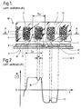
- Figure 4 is a partial section through an engine linear synchronous produced according to the invention and according to a first mode of execution.
- this engine comprises an armature 60 consisting of a pack of sheets, comprising a cylinder head 1 and a plurality of teeth 25 having a first end integral with the cylinder head 1 and a second end, opposite the first and forming a tooth head 62.
- the teeth 25 are arranged regularly with a dental step ⁇ n.
- Each tooth 25 is separated from the next by a notch 2 in which is housed for example the winding 26 of a coil such that those shown in Figure 8 with the reference 30.
- the height of the teeth 25, that is to say the distance between their first and their second end, is designated by the reference H.
- the motor also includes an inductor 61 arranged in look of the teeth heads 62, this inductor 61 being equipped with a plurality of permanent magnets 8 in the form of rectangular parallelepipeds arranged regularly, with a polar step ⁇ p, on a flow return flange 9 flat, made of ferromagnetic material.
- the inductor 61 and the armature 60 are separated by an air gap 7.
- the teeth 25 have a section constant over their entire height H.
- the notches are therefore completely "open” on the side of inductor 61, as opposed to notches of the prior art motors which are said to be "semi-closed”.
- the width bn of the notches 2 is substantially equal to the width bd of the tooth heads 62. In other words, and since the sum of the widths bd and bn is equal to the dental step ⁇ n, the ratio bn / ⁇ n is substantially equal to 0.5.
- this ratio bn / ⁇ n can be between 0.40 and 0.55 approximately.
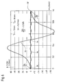
- This phenomenon is illustrated by the diagram of the figure 6.
- This diagram is based on a motor having a pitch dental ⁇ n of 12 mm and a pole pitch ⁇ p of 16 mm (therefore identical to those of the engine of the prior art mentioned above).
- the opening bn of notch is here of 6.3 mm, and the bn / ⁇ n ratio is therefore 0.525.
- the polar step ⁇ p in mm is carried on the abscissa and the reluctant force in Newton is plotted in orderly.
- Curve 35 of the diagram shows the configuration of the reluctant force that would be produced if the armature 60 had only one notch, or force reluctant elementary, and which also has two unstable points 33 and 33 ′ as well as a stable point 34.
- zone 41 is that of motors with semi-closed notches of the prior art, while the zone 45 is that of motors with open notches objects of the present invention.
- the sheets forming armature 60 can be aligned with each others, so that in a cut such as that of the FIG. 4a, the longitudinal axes of the teeth 10 and of the notches 2, represented by dashed lines, are perpendicular to the y direction of movement of inductor 61, not visible in this figure 4a, by compared to the armature 60. It results from this provision a significant simplification of the tools used for assembly of the sheets forming the armature 60.
- the magnets 8 can be arranged so that their edges parallel to the plane of the sole 9 are respectively parallel and perpendicular to the direction of movement y. It follows from this provision a simplification of the tools used for assembling the magnets 8 and the sole 9.
- To manufacture these coils we wind in contiguous turns the wires which form them on an independent template to rectangular core whose section is substantially equal to the section of tooth 25.
- the wire used is generally coated with an adhesive which cures hot. Once the winding is finished, we pass a current in the wire to heat it and stick the turns together to others.
- the coil, thus made compact, can be extracted from the template, then introduced en bloc on a tooth 25 of the armature.
- FIGs 8 and 9 each show the armature 60 of a synchronous motor according to the invention.
- each coil 30 surrounds a single tooth 25 and occupies substantially all of the two notches 2 adjacent to the tooth 25 which it surrounds. The result obviously only one tooth out of two is surrounded by a coil 30.
- each coil 31 also surrounds a single tooth 25, but all of these teeth 25 are surrounded by a coil 31. This results obviously that two adjacent coils 31 occupy, together, substantially all of the notch 2 which separates the two teeth 25 which they surround.
- Figures 10 to 14 are more particularly on how to isolate the windings 26 of armature 60 and how to dissipate the heat produced by these windings 26.
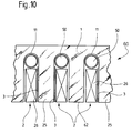
- Figure 10 shows an armature 60 fitted of windings 26 introduced into the notches 2 according to the process which has been described above.
- the figure shows that at bottom of the notch 2, and located between the cylinder head 1 and winding 26, there is a tube 11 in which circulates a coolant 50.
- This system of cooling allows rapid evacuation to outside the heat produced by the winding 26.
- tubes 11 can be prepared in advance with folds at the ends (not shown) giving a serpentine shape.
- Figure 10 also shows a sheet insulator 3 disposed between the winding 26 and the tooth 25, which can be easily inserted into notch 2 since it is open.
- Figure 11 shows an arrangement very close to that of Figure 10 where we find the tube of cooling 11 and the insulating sheet 3.
- the tube 11 is at least partially surrounded by a sheet 12, shown in perspective in FIG. 12, this sheet also being sandwiched between tooth 25 and winding 26 and extending to the head 62 of tooth 25.
- This leaf 12 serves as a means of heat transfer between the winding 26 and the cooling tube 11.
- This sheet is made of thermally conductive material, such as copper or aluminum, or a material composite, such as carbon fiber for example. If the sheet is made of aluminum, it can be oxidized, which allows to remove the insulating sheet 3 and from this further reducing thermal resistance.
- the sheet 12 is metallic, therefore electrically conductive, it will be seat of eddy currents induced by the leakage flow notches 2.
- the notch leakage inductance can then become the main inductor, which is usually a disadvantage.
- One of the ways to reduce the inductance of notch leakage is precisely to use the sheet of heat transfer 12 also as a shield against the notch leakage flow. If this shield becomes too important, we will adjust its effect by machining grooves 13, as they appear in FIG. 12. These grooves 13, like the sheets of electric motors, reduce the importance of eddy currents. A number high grooves eliminates these currents of Eddy, without significantly reducing the capacity of Thermal transfer. Note that you can use for sheet 12 an alloy having a good compromise between its thermal conductivity and its conductivity electric.
- Figures 13 and 14 show a variant of the solution represented by figures 11 and 12.
- the system cooling 14 of Figures 13 and 14 combines into a single piece the conductive sheet 12 and the tube cooling 11 of FIGS. 11 and 12.
- This system 14 can for example be made of aluminum profile.
- FIG 15 shows schematically and partially a synchronous rotary motor according to the present invention, the rotor 50 of which constitutes the inductor 61.
- This rotor 50 has only been shown very schematically by a circle symbolizing its periphery and by its tree 55, but it obviously has a plurality of permanent magnets similar to magnets 8 of the motor of Figure 4 and arranged like these on a flow return sole made of a material ferromagnetic.
- the stator of the motor of figure 15 constitutes its armature 60 and comprises a cylinder head 1 and a plurality of teeth identical to each other and designated alternately by the references 51 and 51 '.
- the teeth 51, 51 ′ are arranged regularly with a dental step ⁇ n and define notches therebetween 2 in which coils 52 and 53 are housed.
- the teeth 51, 51 ' have a constant section over their entire height H, and their width bd is substantially equal to the width bn that the notches 2 have at the height of the teeth heads 62.
- the ratio bn / ⁇ n is also appreciably equal to 0.5.
- these coils 53 are introduced on the teeth 51 ', the teeth 51 being left free.
- the space 54 which remains after the installation of the coils 52 and 53 can be used to house a system cooling, for example one of the systems described in using Figures 10 to 14. It goes without saying, however, that for many motors, only section coils rectangular will be implemented, particularly for large diameter motors.
Landscapes
- Engineering & Computer Science (AREA)
- Power Engineering (AREA)
- Physics & Mathematics (AREA)
- Chemical & Material Sciences (AREA)
- Combustion & Propulsion (AREA)
- Electromagnetism (AREA)
- Linear Motors (AREA)
- Iron Core Of Rotating Electric Machines (AREA)
- Permanent Magnet Type Synchronous Machine (AREA)
- Permanent Field Magnets Of Synchronous Machinery (AREA)
- Windings For Motors And Generators (AREA)
- Reciprocating, Oscillating Or Vibrating Motors (AREA)
- Dc Machiner (AREA)
Description
- la figure 1 est une coupe partielle d'un moteur linéaire synchrone selon l'art antérieur discuté dans le préambule de cette description,
- la figure 1a est une coupe partielle du moteur de la figure 1, faite selon l'axe A-A de cette figure 1,
- la figure 2 montre la configuration de l'induction magnétique B du moteur de la figure 1,
- la figure 3 est un diagramme représentant la force réluctante produite d'une part par une seule encoche du moteur de la figure 1 et d'autre part par huit encoches du même moteur,
- le figure 4 est une coupe partielle d'un moteur linéaire synchrone selon l'invention et selon un premier mode d'exécution,
- la figure 4a est une coupe partielle du moteur de la figure 4, faite selon l'axe A-A de cette figure 4,
- la figure 5 montre la configuration de l'induction magnétique B du moteur de la figure 4,
- la figure 6 est un diagramme représentant la force réluctante produite d'une part par une seule encoche du moteur de la figure 4 et d'autre part par huit encoches du même moteur,
- la figure 7 est un diagramme représentant l'évolution de la force réluctante d'un moteur synchrone de l'invention en fonction du rapport entre la largeur d'encoche et le pas dentaire,
- les figures 8 et 9 montrent deux manières de bobiner un moteur synchrone de l'invention,
- la figure 10 est une coupe partielle dans l'induit d'un moteur synchrone de l'invention selon un deuxième mode d'exécution,
- les figures 11 et 12 montrent un troisième mode d'exécution du moteur selon l'invention, la première en coupe, la seconde en perspective,
- les figures 13 et 14 montrent un quatrième mode d'exécution du moteur selon l'invention, la première en coupe, la seconde en perspective, et
- la figure 15 est une coupe partielle d'un moteur rotatif synchrone selon l'invention.
Claims (11)
- Moteur synchrone comprenant :un induit (60) formé par une culasse (1) et une pluralité de dents (25; 51, 51') fixées à cette culasse qui définissent entre elles des encoches (2);une pluralité de bobines (30; 31; 52, 53) disposées dans lesdites encoches de manière à ce que chacune entoure au moins une desdites dents;un inducteur (61) disposé en regard dudit induit et comprenant une pluralité d'aimants permanents (8) disposés sur une semelle de retour de flux (9); ladite pluralité de dents étant agencée régulièrement avec un pas dentaire déterminé (τn) et ladite pluralité d'aimants permanents étant agencée régulièrement avec un pas polaire déterminé (τp), lesdites dents définissant chacune à leur extrémité libre une tête (62) ayant une première largeur (bd) et lesdites encoches ayant chacune une deuxième largeur (bn) au niveau des têtes desdites dents, la somme desdites première et deuxième largeurs définissant ledit pas dentaire, ce moteur étant caractérisé en ce que ledit pas polaire est différent dudit pas dentaire et en ce que le rapport de ladite deuxième largeur (bn) sur ledit pas dentaire (τn) est compris entre 0,40 et 0,55 environ.
- Moteur synchrone selon la revendication 1, caractérisé en ce que lesdites dents (25; 51, 51') définissent chacune deux flancs sensiblement parallèles de sorte que leur section est sensiblement constante sur toute leur hauteur (H).
- Moteur synchrone selon la revendication 1 ou 2, caractérisé par le fait que chaque bobine (30) entoure une seule desdites dents (25; 51, 51') et occupe sensiblement la totalité des deux encoches (2) adjacentes à celle desdites dents (25; 51, 51') qu'elle entoure, seule une desdites dents (25; 51, 51') sur deux étant entourée par une desdites bobines (30).
- Moteur synchrone selon la revendication 1 ou 2, caractérisé par le fait que chacune desdites dents (25; 51, 51') est entourée par une desdites bobines (31), deux bobines adjacentes occupant ensemble sensiblement la totalité de l'encoche (2) séparant celles des dents qu'elles entourent.
- Moteur synchrone selon l'une des revendications précédentes, caractérisé en ce que ladite première largeur (bd) et ladite deuxième largeur (bn) sont sensiblement égales.
- Moteur synchrone selon l'une quelconque des revendications précédentes, caractérisé par le fait qu'il comporte en outre des moyens de refroidissement comprenant une pluralité de tubes (11) situés chacun dans une desdites encoches (2) entre ladite culasse (1) et la bobine (30; 31; 52, 53) disposée dans cette dernière encoche (2), lesdits tubes (11) étant reliés les uns aux autres de manière à former un serpentin permettant la circulation d'un fluide de refroidissement (50).
- Moteur synchrone selon la revendication 6, caractérisé par le fait que lesdits moyens de refroidissement comprennent en outre une pluralité de feuilles de transfert thermique (12), chacune desdites feuilles (12) étant située dans une desdites encoches (2), entourant au moins partiellement le tube (11) disposé dans cette encoche (2), et étant prise en outre en sandwich entre une des dents (25; 51, 51') délimitant cette encoche (2) et la bobine (30; 31; 52, 53) située dans cette encoche (2).
- Moteur synchrone selon l'une quelconque des revendications précédentes, caractérisé par le fait qu'il est un moteur linéaire.
- Moteur synchrone selon l'une quelconque des revendications 1 à 7, caractérisé par le fait qu'il est un moteur rotatif ayant un stator constitué par ledit induit (60) et un rotor constitué par ledit inducteur (61).
- Moteur synchrone selon la revendication 9, caractérisé par le fait que ledit induit (60) comporte un nombre pair de dents (51, 51') entourées chacune par une desdites bobines (52, 53), deux dents adjacentes (51, 51') étant entourées l'une par une bobine de section au moins sensiblement rectangulaire (52) et l'autre par une bobine de section au moins sensiblement trapézoïdale (53).
- Procédé de fabrication et de mise en place des bobines (52, 53) équipant le moteur rotatif de la revendication 9, caractérisé par le fait qu'il comporte la succession des étapes suivantes :on enroule à spires jointives les fils formant chacune desdites bobines de section rectangulaire (52) sur un gabarit indépendant à noyau rectangulaire dont la section est sensiblement égale à la section de chacune desdites dents (51, 51') pour obtenir une bobine compacte et préformée,on enroule à spires jointives les fils formant chacune desdites bobines section trapézoïdale (53) sur un gabarit indépendant à noyau rectangulaire dont la section est sensiblement égale à la section de chacune desdites dents (51, 51') pour obtenir une bobine compacte et préformée,on introduit chacune desdites bobines de section trapézoïdale (53) sur une desdites dents (51') en laissant libre une desdites dents (51) sur deux, eton introduit chacune desdites bobines de section rectangulaire (52) sur une des dents (51) laissées libres dans l'étape précédente.
Applications Claiming Priority (3)
| Application Number | Priority Date | Filing Date | Title |
|---|---|---|---|
| FR9413714A FR2726948B1 (fr) | 1994-11-16 | 1994-11-16 | Moteur synchrone a aimants permanents |
| FR9413714 | 1994-11-16 | ||
| PCT/EP1995/004344 WO1996015574A2 (fr) | 1994-11-16 | 1995-11-06 | Moteur synchrone a aimants permanents |
Publications (3)
| Publication Number | Publication Date |
|---|---|
| EP0793870A2 EP0793870A2 (fr) | 1997-09-10 |
| EP0793870B1 true EP0793870B1 (fr) | 1998-07-15 |
| EP0793870B2 EP0793870B2 (fr) | 2004-06-30 |
Family
ID=9468842
Family Applications (1)
| Application Number | Title | Priority Date | Filing Date |
|---|---|---|---|
| EP95937867A Expired - Lifetime EP0793870B2 (fr) | 1994-11-16 | 1995-11-06 | Moteur synchrone a aimants permanents |
Country Status (14)
| Country | Link |
|---|---|
| US (1) | US5642013A (fr) |
| EP (1) | EP0793870B2 (fr) |
| JP (1) | JP3793574B2 (fr) |
| KR (1) | KR100400912B1 (fr) |
| CN (1) | CN1074599C (fr) |
| AT (1) | ATE168508T1 (fr) |
| CZ (1) | CZ288081B6 (fr) |
| DE (1) | DE69503521T3 (fr) |
| DK (1) | DK0793870T3 (fr) |
| ES (1) | ES2121429T5 (fr) |
| FR (1) | FR2726948B1 (fr) |
| PL (1) | PL179512B1 (fr) |
| RU (1) | RU2141156C1 (fr) |
| WO (1) | WO1996015574A2 (fr) |
Cited By (6)
| Publication number | Priority date | Publication date | Assignee | Title |
|---|---|---|---|---|
| DE10335793A1 (de) * | 2003-08-05 | 2005-03-10 | Praetec Praez Stechnik Gmbh | Mehrphasiger, vielpoliger Linear- oder Rotationssynchronmotor |
| US7019990B2 (en) | 2003-07-19 | 2006-03-28 | Dr. Johannes Heidenhain Gmbh | Converter with damping mechanism for the avoidance of resonances |
| DE10150520B4 (de) * | 2000-10-31 | 2006-08-24 | Janke Engineering Gmbh | Elektrische Maschine |
| US7701100B2 (en) | 2004-06-02 | 2010-04-20 | Etel S.A. | Synchronous motor |
| DE102011006681A1 (de) * | 2011-04-01 | 2012-10-04 | Aloys Wobben | Polschuh |
| DE102011006680A1 (de) * | 2011-04-01 | 2012-10-04 | Aloys Wobben | Blechpaketanordnung |
Families Citing this family (104)
| Publication number | Priority date | Publication date | Assignee | Title |
|---|---|---|---|---|
| JPH1132457A (ja) * | 1997-07-10 | 1999-02-02 | Toyota Motor Corp | 回転電機のステータ |
| DE29712973U1 (de) * | 1997-07-22 | 1998-11-19 | Strothmann, Rolf, Dr.rer.nat., 66123 Saarbrücken | Elektrische Maschine |
| JP3601757B2 (ja) * | 1998-08-03 | 2004-12-15 | オークマ株式会社 | 永久磁石モータ |
| US6891299B2 (en) * | 2000-05-03 | 2005-05-10 | Moteurs Leroy-Somer | Rotary electric machine having a flux-concentrating rotor and a stator with windings on teeth |
| JP3816727B2 (ja) * | 2000-05-24 | 2006-08-30 | 株式会社東芝 | 永久磁石式リラクタンス型回転電機 |
| DE10041329A1 (de) * | 2000-08-23 | 2002-03-14 | Siemens Ag | Permanentmagneterregter Läufer für einen permanentmagneterregten elektrischen Antrieb, insbesondere für AC-Hauptantriebe |
| IT1319440B1 (it) * | 2000-11-02 | 2003-10-10 | Motor Power Co Srl | Motore elettrico lineare a struttura perfezionata |
| EP1221757A1 (fr) * | 2001-01-09 | 2002-07-10 | Alps Electric Co., Ltd. | Moteur avec rotor intérieur à faible épaisseur pour l'entraínement d'un support d'enrégistrement et appareil de disque utilisant ce moteur |
| JP3593038B2 (ja) * | 2001-01-16 | 2004-11-24 | 三菱電機株式会社 | 車両用交流発電機 |
| FR2821024B1 (fr) | 2001-02-20 | 2003-06-13 | Leroy Somer Moteurs | Element d'entrainement tel qu'une roue motrice ou un treuil de levage, comportant un moteur synchrone |
| FR2823614B1 (fr) * | 2001-04-17 | 2008-07-11 | Leroy Somer Moteurs | Machine tournante electrique comportant un stator forme de secteurs assembles |
| US20020171305A1 (en) * | 2001-04-17 | 2002-11-21 | Moteurs Leroy-Somer | Electric machine having an outer rotor |
| FR2823616B1 (fr) | 2001-04-17 | 2008-07-04 | Leroy Somer Moteurs | Machine electrique comportant au moins un detecteur de champ magnetique |
| DE10133654A1 (de) * | 2001-07-11 | 2003-02-06 | Siemens Ag | Synchronmaschine |
| US20030048011A1 (en) * | 2001-08-21 | 2003-03-13 | Alexander Kashkarov | Magneto-electric machine of linear type |
| CH695648A5 (de) * | 2001-08-29 | 2006-07-14 | Etel Sa | Elektromotor mit Kühlung. |
| US6917136B2 (en) * | 2001-10-01 | 2005-07-12 | Magnemotion, Inc. | Synchronous machine design and manufacturing |
| US6983701B2 (en) * | 2001-10-01 | 2006-01-10 | Magnemotion, Inc. | Suspending, guiding and propelling vehicles using magnetic forces |
| ES2278678T3 (es) * | 2001-11-27 | 2007-08-16 | Rexroth Indramat Gmbh | Motor de ca, sincronico, de campo de desplazamiento. |
| CN100452625C (zh) * | 2001-11-29 | 2009-01-14 | 西门子公司 | 一个直线电动机的空气冷却的线圈单元 |
| US7282821B2 (en) * | 2002-01-28 | 2007-10-16 | Canon Kabushiki Kaisha | Linear motor, stage apparatus, exposure apparatus, and device manufacturing apparatus |
| JP3809381B2 (ja) * | 2002-01-28 | 2006-08-16 | キヤノン株式会社 | リニアモータ、ステージ装置、露光装置及びデバイス製造方法 |
| WO2003071660A2 (fr) * | 2002-02-19 | 2003-08-28 | Parker-Hannifin Corporation | Moteur lineaire avec support de rail magnetique, diminution du couple de crantage a effet d'extremite, et armature segmentee |
| SG121780A1 (en) * | 2002-06-12 | 2006-05-26 | Asml Netherlands Bv | Lithographic apparatus and device manufacturing method |
| DE10229333A1 (de) * | 2002-06-29 | 2004-01-29 | Robert Bosch Gmbh | Elektrische Maschine, insbesondere bürstenlose Maschine mit permanentmagnetisch erregtem Läufer |
| JP2004096803A (ja) * | 2002-08-29 | 2004-03-25 | Mitsubishi Electric Corp | 永久磁石同期モータ |
| FR2853156A1 (fr) * | 2003-03-31 | 2004-10-01 | Leroy Somer Moteurs | Machine electrique synchrone comportant un stator et au moins un rotor et dispositif de commande associe |
| DE10335792A1 (de) * | 2003-08-05 | 2005-03-10 | Praetec Praez Stechnik Gmbh | Mehrphasiger, vielpoliger, schnelllaufender Linear- oder Rotationssynchronmotor |
| DE10361858A1 (de) * | 2003-12-30 | 2005-07-28 | Robert Bosch Gmbh | Ständer für eine elektrische Maschine |
| DE102004010404A1 (de) * | 2004-03-03 | 2005-09-22 | BSH Bosch und Siemens Hausgeräte GmbH | Lineare Antriebseinrichtung mit einem einen Magnetträger aufweisenden Ankerkörper |
| DE102004010849A1 (de) * | 2004-03-05 | 2005-09-22 | BSH Bosch und Siemens Hausgeräte GmbH | Lineare Antriebseinheit mit Schwingungsankerteil und Feder |
| DE102004010847A1 (de) * | 2004-03-05 | 2005-09-22 | BSH Bosch und Siemens Hausgeräte GmbH | Lineare Antriebseinrichtung mit Magnetjochkörper und permanentmagnetischem Ankerkörper |
| US7458454B2 (en) * | 2004-05-07 | 2008-12-02 | Magnemotion, Inc. | Three-dimensional motion using single-pathway based actuators |
| WO2006011614A1 (fr) * | 2004-07-25 | 2006-02-02 | Tsheatronics Co., Ltd. | Moteur mobile lineaire ou courbe et son radiateur |
| DE102004055317A1 (de) * | 2004-11-16 | 2006-05-24 | Bosch Rexroth Aktiengesellschaft | Elektrische Drehfeldmaschine und Primärteil |
| DE102004060506A1 (de) * | 2004-12-16 | 2006-06-29 | Etel S.A. | Rahmenloser Torque-Motor mit Transportsicherung |
| US7230355B2 (en) * | 2004-12-21 | 2007-06-12 | Baldor Electric Company | Linear hybrid brushless servo motor |
| DE102005061388A1 (de) * | 2005-12-02 | 2007-06-06 | Dr. Johannes Heidenhain Gmbh | Pulsweitenmodulationsverfahren |
| US7459900B2 (en) * | 2006-02-03 | 2008-12-02 | Bae Systems Land & Armaments L.P. | Modular current sensor for modularized servo control system |
| US7629764B2 (en) * | 2006-02-03 | 2009-12-08 | Bae Systems Land & Armaments L.P. | Nonlinear motor control techniques |
| NO324241B1 (no) * | 2006-02-28 | 2007-09-17 | Smartmotor As | Anordning ved elektrisk maskin |
| DE102006014343A1 (de) * | 2006-03-28 | 2007-10-11 | Siemens Ag | Verfahren zum Aufbauen einer elektrischen Maschine und Zahnhälften für einen Zahn einer elektrischen Maschine |
| DE102006016249A1 (de) * | 2006-03-31 | 2007-10-04 | Robert Bosch Gmbh | Stator für eine Elektromaschine und Verfahren zur Herstellung |
| DE102006024579B4 (de) * | 2006-05-18 | 2016-09-29 | Dr. Johannes Heidenhain Gmbh | Vorrichtung zur Bestimmung der Position eines entlang mindestens einer Verschieberichtung bewegbaren Objektes |
| DE102006032989A1 (de) * | 2006-07-17 | 2008-01-31 | Siemens Ag | Elektrischer Linearantrieb |
| RU2331150C2 (ru) * | 2006-09-06 | 2008-08-10 | Евгений Дмитриевич Карманов | Синхронная вращающаяся электрическая машина |
| US7791237B2 (en) * | 2006-12-19 | 2010-09-07 | General Electric Company | Fault-tolerant synchronous permanent magnet machine |
| WO2008079144A1 (fr) * | 2006-12-20 | 2008-07-03 | Kulicke And Soffa Industries, Inc. | Moteur linéaire avec ondulation de couple réduite |
| US7566997B2 (en) * | 2007-03-30 | 2009-07-28 | Baldor Electric Company | Gas bearing system |
| DE102007032680A1 (de) | 2007-07-13 | 2009-01-22 | Etel S.A. | Synchronmotor mit mehreren Spulensegmeten |
| DE102007038668A1 (de) | 2007-08-15 | 2009-02-26 | Klaus-Dieter Klement Verwaltungs Gmbh | Elektromotor, insbesondere Synchronmotor |
| NL1035273C2 (nl) * | 2008-04-09 | 2009-10-12 | P3W Invest B V | Stator-element en schuifdeur voorzien daarvan, en een werkwijze voor het verschuiven van een element zoals een deur. |
| US8264116B2 (en) * | 2008-07-22 | 2012-09-11 | Dayton-Phoenix Group, Inc. | Motor/generator phase insulation article and method for manufacturing |
| JP5415161B2 (ja) * | 2008-08-08 | 2014-02-12 | 山洋電気株式会社 | リニア同期モータ |
| EP2182570A1 (fr) * | 2008-10-28 | 2010-05-05 | Siemens Aktiengesellschaft | Agencement pour le refroidissement d'une machine électrique |
| US8616134B2 (en) | 2009-01-23 | 2013-12-31 | Magnemotion, Inc. | Transport system powered by short block linear synchronous motors |
| US9032880B2 (en) | 2009-01-23 | 2015-05-19 | Magnemotion, Inc. | Transport system powered by short block linear synchronous motors and switching mechanism |
| DE102009000681A1 (de) | 2009-02-06 | 2010-08-12 | Robert Bosch Gmbh | Synchronmaschine |
| FR2945388B1 (fr) * | 2009-05-11 | 2013-04-12 | Moving Magnet Technologies M M T | Moteur electrique triphase a faible couple de detente |
| JP5424814B2 (ja) * | 2009-05-21 | 2014-02-26 | 三菱電機株式会社 | 永久磁石型回転電機 |
| DE102009035894A1 (de) * | 2009-08-03 | 2011-02-10 | Wittenstein Ag | Maschine zum Festlegen |
| US8786157B2 (en) | 2010-06-17 | 2014-07-22 | Kollmorgen Corporation | Separable tooth tip armature construction |
| CN101895187B (zh) * | 2010-08-17 | 2012-06-27 | 哈尔滨工业大学 | 直线永磁同步电机 |
| US20120280579A1 (en) * | 2011-05-06 | 2012-11-08 | Bose Corporation | Linear moving magnet motor cogging force ripple reducing |
| US8791608B2 (en) | 2011-07-11 | 2014-07-29 | Baldor Electric Company | Primary for linear drive motor with solid steel stacks |
| US8803371B2 (en) | 2011-07-11 | 2014-08-12 | Baldor Electric Company | Secondary for linear drive motor comprising sheet of highly permeable magnetic material having synchronized motor teeth, encoder teeth, and commutation tracks integrally formed therein |
| US8922068B2 (en) | 2011-07-11 | 2014-12-30 | Baldor Electric Company | Linear drive motor with improved bearing system |
| US8418350B2 (en) | 2011-07-11 | 2013-04-16 | Baldor Electric Company | Method of forming a secondary for linear drive motor comprising sheet of highly permeable magnetic material having synchronized motor teeth, encoder teeth, and commutation tracks integrally formed therein |
| JP5293984B1 (ja) | 2011-12-27 | 2013-09-18 | 株式会社安川電機 | モータ |
| JP5421396B2 (ja) | 2012-01-13 | 2014-02-19 | ファナック株式会社 | 主歯及び副歯を有する鉄心コアを備える電動機 |
| EP2680408B1 (fr) | 2012-06-26 | 2014-12-17 | Etel S. A.. | Châssis doté d'un refroidissement intégré pour un entraînement électrique |
| EP2717434B1 (fr) | 2012-10-08 | 2017-12-20 | Etel S. A.. | Pièce intercalaire pour stabiliser et isoler une tête de bobine |
| TWI488409B (zh) | 2012-11-21 | 2015-06-11 | Ind Tech Res Inst | 定子模組及其磁力產生構件 |
| RU2534225C2 (ru) * | 2013-02-01 | 2014-11-27 | Алексей Владимирович Дозоров | Электрическая машина |
| WO2015021977A2 (fr) * | 2013-08-13 | 2015-02-19 | Schaeffler Technologies Gmbh & Co. Kg | Dispositif de transfert de chaleur, et module enroulement formé en intégrant ce dispositif |
| CN105453385B (zh) * | 2013-08-14 | 2019-05-03 | 雅马哈发动机株式会社 | 同步驱动电机 |
| CN105474521B (zh) * | 2013-08-14 | 2019-03-01 | 雅马哈发动机株式会社 | 同步型驱动马达 |
| CN105813886B (zh) | 2013-09-21 | 2018-04-03 | 麦克纳莫绅有限公司 | 用于包装和其它用途的线性电机运输 |
| WO2015110240A1 (fr) * | 2014-01-22 | 2015-07-30 | Asml Netherlands B.V. | Ensemble bobine, actionneur electromagnetique, dispositif de positionnement d'etage, appareil lithographique et procede de fabrication de dispositif |
| EP2922185A1 (fr) * | 2014-03-21 | 2015-09-23 | Siemens Aktiengesellschaft | Refroidissement d'une pièce active d'une machine électrique |
| EP2930830B1 (fr) | 2014-04-08 | 2021-09-29 | Etel S.A. | Piste magnétique pour un dispositif de transport |
| EP2955824B1 (fr) | 2014-06-11 | 2017-05-31 | Etel S. A.. | Élément secondaire d'un moteur synchrone doté d'un dispositif de protection pour aimants |
| DE102014216148A1 (de) | 2014-08-14 | 2016-02-18 | Wobben Properties Gmbh | Synchrongenerator, insbesondere vielpoliger Synchron-Ringgenerator einer getriebelosen Windenergieanlage, und Windenergieanlage mit selbigem |
| RU2018108629A (ru) | 2015-08-11 | 2019-09-12 | Дженезис Роботикс Энд Мотион Текнолоджиз Канада, Улс | Электрическая машина |
| US11139707B2 (en) | 2015-08-11 | 2021-10-05 | Genesis Robotics And Motion Technologies Canada, Ulc | Axial gap electric machine with permanent magnets arranged between posts |
| JP5937263B1 (ja) * | 2015-08-18 | 2016-06-22 | 山洋電気株式会社 | リニアモータ |
| US11043885B2 (en) | 2016-07-15 | 2021-06-22 | Genesis Robotics And Motion Technologies Canada, Ulc | Rotary actuator |
| RU2658301C2 (ru) * | 2016-09-06 | 2018-06-20 | Олег Анатольевич Рокачевский | Синхронный линейный электродвигатель |
| RU2658296C2 (ru) * | 2016-09-13 | 2018-06-20 | Олег Анатольевич Рокачевский | Линейный электродвигатель |
| EP3324521B1 (fr) | 2016-11-16 | 2020-04-15 | Etel S. A.. | Plaque de refroidissement pour moteur linéaire |
| EP3337019B1 (fr) | 2016-12-16 | 2019-04-17 | Etel S. A.. | Part primaire comprenant une plaque de refroidissement |
| US11139727B2 (en) * | 2016-12-23 | 2021-10-05 | Korea Electrotechnology Research Institute | Permanent magnet electrical machine for reducing detent force |
| EP3480929B1 (fr) | 2017-11-03 | 2021-04-28 | Etel S.A. | Carter refroidi pour le stator d'entraînement direct |
| RU2679002C1 (ru) * | 2018-01-17 | 2019-02-05 | Олег Анатольевич Рокачевский | Синхронный электродвигатель |
| EP3648312B1 (fr) | 2018-10-29 | 2022-12-14 | Etel S.A. | Bobine préfabriquée pour un entraînement direct |
| EP3730986B1 (fr) | 2019-04-24 | 2023-02-15 | Etel S.A. | Organe de couplage pour un dispositif de positionnement, dispositif de positionnement doté d'un organe de couplage ainsi que procédé de fabrication |
| EP3789808B1 (fr) | 2019-09-05 | 2023-12-20 | Etel S.A. | Organe de couplage pour un dispositif de positionnement ainsi que dispositif de positionnement doté d'un organe de couplage |
| WO2022058939A1 (fr) | 2020-09-21 | 2022-03-24 | Evr Motors Ltd. | Machine électrique à flux radial |
| US12081073B2 (en) | 2021-10-04 | 2024-09-03 | Evr Motors Ltd | Electric machine with multi-tapered yokes |
| DE112022005286B4 (de) * | 2022-02-21 | 2025-11-20 | Mitsubishi Electric Corporation | Lineartransportsystem |
| US12046949B1 (en) | 2023-12-28 | 2024-07-23 | Evr Motors Ltd | Electric machine with coils bridged with toothed clips |
| US12278519B1 (en) | 2023-12-28 | 2025-04-15 | Evr Motors Ltd | Electric machine with multiple toothed spacers in coils |
| US12136869B1 (en) | 2023-12-28 | 2024-11-05 | Evr Motors Ltd | Heat dissipation plate for electric machine |
| WO2025209837A1 (fr) * | 2024-04-04 | 2025-10-09 | Gea Mechanical Equipment Italia S.P.A. | Machine vernier linéaire |
Family Cites Families (26)
| Publication number | Priority date | Publication date | Assignee | Title |
|---|---|---|---|---|
| DE249091C (fr) * | ||||
| DE92958C (fr) † | ||||
| US2092058A (en) * | 1936-11-28 | 1937-09-07 | Westinghouse Electric & Mfg Co | Field coil for motors |
| US2169100A (en) * | 1938-12-21 | 1939-08-08 | Gen Electric | Dynamo-electric machine |
| DE1012681B (de) † | 1953-09-09 | 1957-07-25 | Siemens Ag | Synchronisierte Asynchronmaschine |
| CA560198A (fr) † | 1954-11-23 | 1958-07-08 | T. Akers Harry | Generateurs electriques aeres par conducteur |
| DE1538965A1 (de) † | 1966-06-02 | 1970-01-29 | Philips Patentverwaltung | Vorrichtung zur induktiven Spannungserzeugung,vorwiegend zu Messzwecken |
| DE2339318C3 (de) † | 1973-08-03 | 1978-09-28 | Aeg-Elotherm Gmbh, 5630 Remscheid | Linearer Wanderfeldinduktor für den Transport geschmolzener Metalle |
| DE2842195C3 (de) † | 1978-09-28 | 1984-02-02 | Gerhard Berger GmbH & Co KG Fabrik elektrischer Geräte, 7630 Lahr | Synchronmotor mit permanentmagnetischem Rotor |
| US4260926A (en) * | 1979-03-16 | 1981-04-07 | Societe Elpalux | Variable reluctance electric motor with progressively saturable poles |
| US4725750A (en) * | 1980-11-20 | 1988-02-16 | Hughes Aircraft Company | Permanent magnet rotary machine |
| US4424463A (en) * | 1981-05-27 | 1984-01-03 | Musil J Donald | Apparatus for minimizing magnetic cogging in an electrical machine |
| DE3246596C1 (de) † | 1982-12-16 | 1984-04-19 | Berger Lahr GmbH, 7630 Lahr | Synchronmotor |
| US4554491A (en) * | 1984-08-10 | 1985-11-19 | Msl Industries, Inc. | Brushless DC motor having a laminated stator with a single stator winding |
| JPS61106035A (ja) * | 1984-10-30 | 1986-05-24 | Toshiba Corp | スロツト鉄心形直流モ−タ |
| JPS61187603A (ja) * | 1985-02-15 | 1986-08-21 | Yaskawa Electric Mfg Co Ltd | リニアレゾルバ |
| JP2664908B2 (ja) * | 1987-09-21 | 1997-10-22 | 群馬日本電気株式会社 | リニアパルスモータ |
| US4862024A (en) * | 1987-12-14 | 1989-08-29 | United Technologies Corp. | Heat dissipation in an electric motor |
| JPH01238406A (ja) * | 1988-03-17 | 1989-09-22 | Fuji Electric Co Ltd | 吸引形磁気浮上車の浮上推進装置 |
| US4859891A (en) * | 1988-04-08 | 1989-08-22 | General Electric Company | Subslot liner for rotor of dynamoelectric machine |
| US4922165A (en) * | 1988-06-06 | 1990-05-01 | General Electric Company | Core and slot liner |
| SU1739441A1 (ru) * | 1988-11-21 | 1992-06-07 | Харьковский авиационный институт им.Н.Е.Жуковского | Статор электрической машины |
| WO1990009698A2 (fr) * | 1989-02-08 | 1990-08-23 | Zahnradfabrik Friedrichshafen Ag | Moteur a champ tournant excite par des aimants permanents |
| US5093543A (en) * | 1990-10-26 | 1992-03-03 | Electrical Insulation Suppliers, Inc. | Motor phase insulation article and method of making the same |
| GB2258765B (en) * | 1991-06-27 | 1996-01-10 | Dana Corp | Variable reluctance motor having foil wire wound coils |
| DE4133723A1 (de) † | 1991-10-11 | 1993-04-15 | Zahnradfabrik Friedrichshafen | Drehfeldmotor |
-
1994
- 1994-11-16 FR FR9413714A patent/FR2726948B1/fr not_active Expired - Fee Related
-
1995
- 1995-03-20 US US08/406,599 patent/US5642013A/en not_active Expired - Lifetime
- 1995-11-06 RU RU97110090A patent/RU2141156C1/ru active
- 1995-11-06 EP EP95937867A patent/EP0793870B2/fr not_active Expired - Lifetime
- 1995-11-06 WO PCT/EP1995/004344 patent/WO1996015574A2/fr not_active Ceased
- 1995-11-06 ES ES95937867T patent/ES2121429T5/es not_active Expired - Lifetime
- 1995-11-06 CN CN95196264A patent/CN1074599C/zh not_active Expired - Fee Related
- 1995-11-06 CZ CZ19971480A patent/CZ288081B6/cs not_active IP Right Cessation
- 1995-11-06 KR KR1019970703242A patent/KR100400912B1/ko not_active Expired - Lifetime
- 1995-11-06 JP JP51569896A patent/JP3793574B2/ja not_active Expired - Fee Related
- 1995-11-06 PL PL95320219A patent/PL179512B1/pl not_active IP Right Cessation
- 1995-11-06 DE DE69503521T patent/DE69503521T3/de not_active Expired - Lifetime
- 1995-11-06 AT AT95937867T patent/ATE168508T1/de active
- 1995-11-06 DK DK95937867T patent/DK0793870T3/da active
Cited By (7)
| Publication number | Priority date | Publication date | Assignee | Title |
|---|---|---|---|---|
| DE10150520B4 (de) * | 2000-10-31 | 2006-08-24 | Janke Engineering Gmbh | Elektrische Maschine |
| US7019990B2 (en) | 2003-07-19 | 2006-03-28 | Dr. Johannes Heidenhain Gmbh | Converter with damping mechanism for the avoidance of resonances |
| DE10335793A1 (de) * | 2003-08-05 | 2005-03-10 | Praetec Praez Stechnik Gmbh | Mehrphasiger, vielpoliger Linear- oder Rotationssynchronmotor |
| US7701100B2 (en) | 2004-06-02 | 2010-04-20 | Etel S.A. | Synchronous motor |
| DE102011006681A1 (de) * | 2011-04-01 | 2012-10-04 | Aloys Wobben | Polschuh |
| DE102011006680A1 (de) * | 2011-04-01 | 2012-10-04 | Aloys Wobben | Blechpaketanordnung |
| WO2012130814A2 (fr) | 2011-04-01 | 2012-10-04 | Wobben Properties Gmbh | Épanouissement polaire |
Also Published As
| Publication number | Publication date |
|---|---|
| RU2141156C1 (ru) | 1999-11-10 |
| FR2726948A1 (fr) | 1996-05-15 |
| EP0793870B2 (fr) | 2004-06-30 |
| JPH10511837A (ja) | 1998-11-10 |
| ES2121429T5 (es) | 2005-03-01 |
| JP3793574B2 (ja) | 2006-07-05 |
| DE69503521D1 (de) | 1998-08-20 |
| US5642013A (en) | 1997-06-24 |
| FR2726948B1 (fr) | 1996-12-20 |
| KR100400912B1 (ko) | 2004-03-12 |
| CN1074599C (zh) | 2001-11-07 |
| ATE168508T1 (de) | 1998-08-15 |
| PL179512B1 (pl) | 2000-09-29 |
| ES2121429T3 (es) | 1998-11-16 |
| PL320219A1 (en) | 1997-09-15 |
| DE69503521T2 (de) | 1999-03-04 |
| CZ288081B6 (cs) | 2001-04-11 |
| EP0793870A2 (fr) | 1997-09-10 |
| WO1996015574A3 (fr) | 1996-07-25 |
| WO1996015574A2 (fr) | 1996-05-23 |
| KR970707624A (ko) | 1997-12-01 |
| DE69503521T3 (de) | 2005-03-03 |
| CN1163682A (zh) | 1997-10-29 |
| CZ148097A3 (en) | 1997-10-15 |
| DK0793870T3 (da) | 1999-04-19 |
Similar Documents
| Publication | Publication Date | Title |
|---|---|---|
| EP0793870B1 (fr) | Moteur synchrone a aimants permanents | |
| FR3046888A1 (fr) | Stator pour machine electromagnetique a flux axial avec des portions unitaires formant une couronne du stator | |
| FR2819117A1 (fr) | Alternateur a elements conducteurs en epingle pour vehicule automobile | |
| EP3931947A1 (fr) | Stator de machine electrique tournante | |
| EP3130061A2 (fr) | Stator de machine electrique tournante | |
| EP3586426A1 (fr) | Machine electrique tournante a flux axial | |
| FR3098745A1 (fr) | Procédé de soudage sans apport de matière | |
| EP2209192A1 (fr) | Machine électrique tournante, en particulier pour un démarreur de véhicule automobile | |
| EP1251622B1 (fr) | Bobine pour machine électrique tournante | |
| FR3066333A1 (fr) | Rotor a poles vrilles pour machine electrique tournante synchrone. | |
| CH715403B1 (fr) | Machine électrique rotative. | |
| EP3931941A1 (fr) | Stator de machine electrique tournante | |
| WO2020174187A1 (fr) | Stator de machine électrique tournante | |
| FR2538970A1 (fr) | Circuit magnetique pour machine electrique a poles saillants | |
| EP3304694A2 (fr) | Armature électromagnetique pour une machine électrique tournante | |
| FR2711456A1 (fr) | Machine électrique tournante et son procédé de fabrication. | |
| WO2019206830A1 (fr) | Rotor de machine electrique tournante | |
| FR2820896A1 (fr) | Alternateur pour vehicule automobile | |
| WO2023285754A1 (fr) | Stator de machine électrique tournante et procédé de fabrication | |
| EP4416826A2 (fr) | Stator de machine électrique tournante | |
| WO2021019152A1 (fr) | Stator de machine électrique tournante avec bobinage simplifié | |
| WO2025190978A1 (fr) | Stator circulaire pour bicyclette a assistance electrique | |
| EP2804299B1 (fr) | Machine électrique tournante synchrone polyphasée | |
| FR3146771A1 (fr) | Isolant de bobine destiné à être positionné autour d'une dent d'un stator ou d'un rotor d'une machine électrique | |
| WO2021019158A1 (fr) | Conducteur multibrin avec adhérent |
Legal Events
| Date | Code | Title | Description |
|---|---|---|---|
| PUAI | Public reference made under article 153(3) epc to a published international application that has entered the european phase |
Free format text: ORIGINAL CODE: 0009012 |
|
| 17P | Request for examination filed |
Effective date: 19970616 |
|
| AK | Designated contracting states |
Kind code of ref document: A2 Designated state(s): AT BE CH DE DK ES FR GB IE IT LI NL SE |
|
| GRAG | Despatch of communication of intention to grant |
Free format text: ORIGINAL CODE: EPIDOS AGRA |
|
| GRAG | Despatch of communication of intention to grant |
Free format text: ORIGINAL CODE: EPIDOS AGRA |
|
| GRAH | Despatch of communication of intention to grant a patent |
Free format text: ORIGINAL CODE: EPIDOS IGRA |
|
| 17Q | First examination report despatched |
Effective date: 19971218 |
|
| GRAH | Despatch of communication of intention to grant a patent |
Free format text: ORIGINAL CODE: EPIDOS IGRA |
|
| GRAA | (expected) grant |
Free format text: ORIGINAL CODE: 0009210 |
|
| AK | Designated contracting states |
Kind code of ref document: B1 Designated state(s): AT BE CH DE DK ES FR GB IE IT LI NL SE |
|
| REF | Corresponds to: |
Ref document number: 168508 Country of ref document: AT Date of ref document: 19980815 Kind code of ref document: T |
|
| REG | Reference to a national code |
Ref country code: CH Ref legal event code: EP |
|
| REF | Corresponds to: |
Ref document number: 69503521 Country of ref document: DE Date of ref document: 19980820 |
|
| REG | Reference to a national code |
Ref country code: CH Ref legal event code: NV Representative=s name: ICB INGENIEURS CONSEILS EN BREVETS SA |
|
| REG | Reference to a national code |
Ref country code: IE Ref legal event code: FG4D Free format text: FRENCH |
|
| GBT | Gb: translation of ep patent filed (gb section 77(6)(a)/1977) |
Effective date: 19980928 |
|
| REG | Reference to a national code |
Ref country code: ES Ref legal event code: FG2A Ref document number: 2121429 Country of ref document: ES Kind code of ref document: T3 |
|
| REG | Reference to a national code |
Ref country code: DK Ref legal event code: T3 |
|
| PLBI | Opposition filed |
Free format text: ORIGINAL CODE: 0009260 |
|
| 26 | Opposition filed |
Opponent name: SIEMENS AG Effective date: 19990409 |
|
| PLBF | Reply of patent proprietor to notice(s) of opposition |
Free format text: ORIGINAL CODE: EPIDOS OBSO |
|
| PLBF | Reply of patent proprietor to notice(s) of opposition |
Free format text: ORIGINAL CODE: EPIDOS OBSO |
|
| REG | Reference to a national code |
Ref country code: CH Ref legal event code: PUE Owner name: WAVRE, NICOLAS TRANSFER- ETEL S.A. |
|
| PLBF | Reply of patent proprietor to notice(s) of opposition |
Free format text: ORIGINAL CODE: EPIDOS OBSO |
|
| REG | Reference to a national code |
Ref country code: FR Ref legal event code: TP |
|
| RAP2 | Party data changed (patent owner data changed or rights of a patent transferred) |
Owner name: ETEL S.A. |
|
| RIN2 | Information on inventor provided after grant (corrected) |
Free format text: WAVRE, NICOLAS |
|
| TPAD | Observations filed by third parties |
Free format text: ORIGINAL CODE: EPIDOS TIPA |
|
| REG | Reference to a national code |
Ref country code: GB Ref legal event code: 732E |
|
| NLS | Nl: assignments of ep-patents |
Owner name: ETEL S.A. |
|
| NLT2 | Nl: modifications (of names), taken from the european patent patent bulletin |
Owner name: ETEL S.A. |
|
| REG | Reference to a national code |
Ref country code: ES Ref legal event code: PC2A |
|
| PGFP | Annual fee paid to national office [announced via postgrant information from national office to epo] |
Ref country code: DK Payment date: 20001026 Year of fee payment: 6 |
|
| PGFP | Annual fee paid to national office [announced via postgrant information from national office to epo] |
Ref country code: IE Payment date: 20001102 Year of fee payment: 6 |
|
| PG25 | Lapsed in a contracting state [announced via postgrant information from national office to epo] |
Ref country code: IE Free format text: LAPSE BECAUSE OF FAILURE TO SUBMIT A TRANSLATION OF THE DESCRIPTION OR TO PAY THE FEE WITHIN THE PRESCRIBED TIME-LIMIT Effective date: 20011106 Ref country code: DK Free format text: LAPSE BECAUSE OF NON-PAYMENT OF DUE FEES Effective date: 20011106 |
|
| REG | Reference to a national code |
Ref country code: GB Ref legal event code: IF02 |
|
| REG | Reference to a national code |
Ref country code: DK Ref legal event code: EBP |
|
| REG | Reference to a national code |
Ref country code: IE Ref legal event code: MM4A |
|
| PUAH | Patent maintained in amended form |
Free format text: ORIGINAL CODE: 0009272 |
|
| STAA | Information on the status of an ep patent application or granted ep patent |
Free format text: STATUS: PATENT MAINTAINED AS AMENDED |
|
| 27A | Patent maintained in amended form |
Effective date: 20040630 |
|
| AK | Designated contracting states |
Kind code of ref document: B2 Designated state(s): AT BE CH DE DK ES FR GB IE IT LI NL SE |
|
| REG | Reference to a national code |
Ref country code: CH Ref legal event code: AEN Free format text: MAINTIEN DU BREVET DONT L'ETENDUE A ETE MODIFIEE |
|
| NLR2 | Nl: decision of opposition |
Effective date: 20040630 |
|
| REG | Reference to a national code |
Ref country code: SE Ref legal event code: RPEO |
|
| GBTA | Gb: translation of amended ep patent filed (gb section 77(6)(b)/1977) | ||
| NLR3 | Nl: receipt of modified translations in the netherlands language after an opposition procedure | ||
| REG | Reference to a national code |
Ref country code: ES Ref legal event code: DC2A Date of ref document: 20040929 Kind code of ref document: T5 |
|
| PLAB | Opposition data, opponent's data or that of the opponent's representative modified |
Free format text: ORIGINAL CODE: 0009299OPPO |
|
| PGFP | Annual fee paid to national office [announced via postgrant information from national office to epo] |
Ref country code: ES Payment date: 20081121 Year of fee payment: 14 |
|
| PGFP | Annual fee paid to national office [announced via postgrant information from national office to epo] |
Ref country code: SE Payment date: 20081114 Year of fee payment: 14 |
|
| PGFP | Annual fee paid to national office [announced via postgrant information from national office to epo] |
Ref country code: BE Payment date: 20090126 Year of fee payment: 14 |
|
| PGFP | Annual fee paid to national office [announced via postgrant information from national office to epo] |
Ref country code: GB Payment date: 20091119 Year of fee payment: 15 |
|
| BERE | Be: lapsed |
Owner name: S.A *ETEL Effective date: 20091130 |
|
| EUG | Se: european patent has lapsed | ||
| PG25 | Lapsed in a contracting state [announced via postgrant information from national office to epo] |
Ref country code: BE Free format text: LAPSE BECAUSE OF NON-PAYMENT OF DUE FEES Effective date: 20091130 |
|
| REG | Reference to a national code |
Ref country code: ES Ref legal event code: FD2A Effective date: 20110307 |
|
| PG25 | Lapsed in a contracting state [announced via postgrant information from national office to epo] |
Ref country code: SE Free format text: LAPSE BECAUSE OF NON-PAYMENT OF DUE FEES Effective date: 20091107 |
|
| GBPC | Gb: european patent ceased through non-payment of renewal fee |
Effective date: 20101106 |
|
| PG25 | Lapsed in a contracting state [announced via postgrant information from national office to epo] |
Ref country code: ES Free format text: LAPSE BECAUSE OF NON-PAYMENT OF DUE FEES Effective date: 20110304 |
|
| PG25 | Lapsed in a contracting state [announced via postgrant information from national office to epo] |
Ref country code: ES Free format text: LAPSE BECAUSE OF NON-PAYMENT OF DUE FEES Effective date: 20091107 |
|
| PG25 | Lapsed in a contracting state [announced via postgrant information from national office to epo] |
Ref country code: GB Free format text: LAPSE BECAUSE OF NON-PAYMENT OF DUE FEES Effective date: 20101106 |
|
| PGFP | Annual fee paid to national office [announced via postgrant information from national office to epo] |
Ref country code: CH Payment date: 20131121 Year of fee payment: 19 Ref country code: AT Payment date: 20131113 Year of fee payment: 19 Ref country code: DE Payment date: 20131121 Year of fee payment: 19 Ref country code: FR Payment date: 20131120 Year of fee payment: 19 |
|
| PGFP | Annual fee paid to national office [announced via postgrant information from national office to epo] |
Ref country code: IT Payment date: 20131129 Year of fee payment: 19 Ref country code: NL Payment date: 20131121 Year of fee payment: 19 |
|
| REG | Reference to a national code |
Ref country code: DE Ref legal event code: R119 Ref document number: 69503521 Country of ref document: DE |
|
| REG | Reference to a national code |
Ref country code: NL Ref legal event code: V1 Effective date: 20150601 |
|
| REG | Reference to a national code |
Ref country code: CH Ref legal event code: PL |
|
| REG | Reference to a national code |
Ref country code: AT Ref legal event code: MM01 Ref document number: 168508 Country of ref document: AT Kind code of ref document: T Effective date: 20141106 |
|
| PG25 | Lapsed in a contracting state [announced via postgrant information from national office to epo] |
Ref country code: CH Free format text: LAPSE BECAUSE OF NON-PAYMENT OF DUE FEES Effective date: 20141130 Ref country code: LI Free format text: LAPSE BECAUSE OF NON-PAYMENT OF DUE FEES Effective date: 20141130 |
|
| REG | Reference to a national code |
Ref country code: FR Ref legal event code: ST Effective date: 20150731 |
|
| PG25 | Lapsed in a contracting state [announced via postgrant information from national office to epo] |
Ref country code: AT Free format text: LAPSE BECAUSE OF NON-PAYMENT OF DUE FEES Effective date: 20141106 Ref country code: NL Free format text: LAPSE BECAUSE OF NON-PAYMENT OF DUE FEES Effective date: 20150601 |
|
| PG25 | Lapsed in a contracting state [announced via postgrant information from national office to epo] |
Ref country code: DE Free format text: LAPSE BECAUSE OF NON-PAYMENT OF DUE FEES Effective date: 20150602 |
|
| PG25 | Lapsed in a contracting state [announced via postgrant information from national office to epo] |
Ref country code: FR Free format text: LAPSE BECAUSE OF NON-PAYMENT OF DUE FEES Effective date: 20141201 |
|
| PG25 | Lapsed in a contracting state [announced via postgrant information from national office to epo] |
Ref country code: IT Free format text: LAPSE BECAUSE OF NON-PAYMENT OF DUE FEES Effective date: 20141106 |