EP0793920A1 - Einsatzstück für Snowboardstiefel - Google Patents
Einsatzstück für Snowboardstiefel Download PDFInfo
- Publication number
- EP0793920A1 EP0793920A1 EP97102634A EP97102634A EP0793920A1 EP 0793920 A1 EP0793920 A1 EP 0793920A1 EP 97102634 A EP97102634 A EP 97102634A EP 97102634 A EP97102634 A EP 97102634A EP 0793920 A1 EP0793920 A1 EP 0793920A1
- Authority
- EP
- European Patent Office
- Prior art keywords
- lateral
- wings
- snowboard boot
- leg
- insert according
- Prior art date
- Legal status (The legal status is an assumption and is not a legal conclusion. Google has not performed a legal analysis and makes no representation as to the accuracy of the status listed.)
- Granted
Links
- 238000005452 bending Methods 0.000 claims abstract description 13
- 210000003423 ankle Anatomy 0.000 claims abstract description 7
- 244000309466 calf Species 0.000 claims abstract description 6
- 230000000903 blocking effect Effects 0.000 claims description 2
- 210000004744 fore-foot Anatomy 0.000 claims description 2
- 210000002414 leg Anatomy 0.000 description 15
- 244000245420 ail Species 0.000 description 6
- 238000010276 construction Methods 0.000 description 3
- JTJMJGYZQZDUJJ-UHFFFAOYSA-N phencyclidine Chemical compound C1CCCCN1C1(C=2C=CC=CC=2)CCCCC1 JTJMJGYZQZDUJJ-UHFFFAOYSA-N 0.000 description 3
- 239000006260 foam Substances 0.000 description 2
- 210000002683 foot Anatomy 0.000 description 2
- 208000014674 injury Diseases 0.000 description 2
- 210000003127 knee Anatomy 0.000 description 2
- 239000010985 leather Substances 0.000 description 2
- 239000000463 material Substances 0.000 description 2
- 239000004033 plastic Substances 0.000 description 2
- 230000000630 rising effect Effects 0.000 description 2
- 238000009958 sewing Methods 0.000 description 2
- 230000008733 trauma Effects 0.000 description 2
- 240000008042 Zea mays Species 0.000 description 1
- 230000006978 adaptation Effects 0.000 description 1
- 238000004026 adhesive bonding Methods 0.000 description 1
- 210000000544 articulatio talocruralis Anatomy 0.000 description 1
- 230000005540 biological transmission Effects 0.000 description 1
- 239000002131 composite material Substances 0.000 description 1
- 238000006073 displacement reaction Methods 0.000 description 1
- 239000004744 fabric Substances 0.000 description 1
- 239000000835 fiber Substances 0.000 description 1
- 239000002184 metal Substances 0.000 description 1
- 230000002028 premature Effects 0.000 description 1
- 238000011084 recovery Methods 0.000 description 1
- 230000002787 reinforcement Effects 0.000 description 1
- 210000002435 tendon Anatomy 0.000 description 1
- 239000004753 textile Substances 0.000 description 1
- 238000003466 welding Methods 0.000 description 1
Images

Classifications
-
- A—HUMAN NECESSITIES
- A63—SPORTS; GAMES; AMUSEMENTS
- A63C—SKATES; SKIS; ROLLER SKATES; DESIGN OR LAYOUT OF COURTS, RINKS OR THE LIKE
- A63C10/00—Snowboard bindings
- A63C10/24—Calf or heel supports, e.g. adjustable high back or heel loops
-
- A—HUMAN NECESSITIES
- A43—FOOTWEAR
- A43B—CHARACTERISTIC FEATURES OF FOOTWEAR; PARTS OF FOOTWEAR
- A43B5/00—Footwear for sporting purposes
- A43B5/04—Ski or like boots
- A43B5/0401—Snowboard boots
-
- A—HUMAN NECESSITIES
- A43—FOOTWEAR
- A43B—CHARACTERISTIC FEATURES OF FOOTWEAR; PARTS OF FOOTWEAR
- A43B5/00—Footwear for sporting purposes
- A43B5/04—Ski or like boots
- A43B5/0486—Ski or like boots characterized by the material
- A43B5/049—Ski or like boots characterized by the material with an upper made of composite material, e.g. fibers or core embedded in a matrix
-
- A—HUMAN NECESSITIES
- A63—SPORTS; GAMES; AMUSEMENTS
- A63C—SKATES; SKIS; ROLLER SKATES; DESIGN OR LAYOUT OF COURTS, RINKS OR THE LIKE
- A63C10/00—Snowboard bindings
- A63C10/14—Interfaces, e.g. in the shape of a plate
- A63C10/145—Interfaces, e.g. in the shape of a plate between two superimposed binding systems, e.g. cradle
Definitions
- the invention relates to a snowboard boot insert as well as to a snowboard boot fitted with such an insert more particularly suited to the practice of disciplines such as "free-ride” or "free-style”.
- the surfer who practices the new disciplines is led to take support and adopt a very prone attitude forwards or backwards. He must then flex one of the legs strongly inward in the direction of bringing one knee closer to the board. The other leg also undergoes a less pronounced lateral outward tilt. To facilitate bending the leg inward while maintaining a certain balance, the surfer can bend the knee; which causes the lower leg to flex from back to front.
- Document EP-A1-646334 relates to a snowboard boot which comprises a flexible inner part in the form of a boot, an outer part also in the form of a shoe, with a flexible upper, and, is disposed between these two parts, a rigid insert on which is articulated at the level of the articulation of the foot and the lower leg along an axis passing through the longitudinal plane of the shoe, a rigid dorsal part which encloses the calf.
- This shoe has the advantage of favoring the taking of back side turns very efficiently thanks to the rigid dorsal part having a rear support and which is inserted directly into the shoe while maintaining a certain lateral laxity, indifferently on the interior side. or outside, to allow the surfer to adopt more or less bent leg positions.
- the shoe also retains the comfort of a boot of the flexible type by the presence of a internal liner and an external flexible upper. This comfort is appreciable in particular during the use of the shoe for walking.
- the rigid articulated insert has several major drawbacks.
- the rear support part pivots during combined stresses in postero-anterior flexion of the leg and in lateral flexion; which causes a twist of the insert which affects the rod and can cause comfort problems.
- such an insert is not suitable for controlling the amplitude of the postero-anterior flexion; which can lead to tendon trauma due to hyper-flexion.
- the insert does not provide a satisfactory solution in the need to concretely manage an asymmetry of internal / external lateral laxity. In other words, it has been realized that it is necessary for the upper of a snowboard boot to have greater lateral laxity on the internal side in particular than on the external side and that the solution of document EP-A1-646334 does not ignore it.
- the present invention therefore presents itself as an improvement to the inserts intended to equip boots or shoes of the 'flexible' type, which are particularly appreciated in modern snowboarding.
- the invention aims to solve the aforementioned drawbacks by proposing a solution that is both simple, functional and that adapts to any type of existing boot or shoe.
- Such an insert retains the essential rear support function but is articulated differently and is therefore no longer subject to a twisting phenomenon by accompanying the combined postero-anterior and lateral flexion of the leg in a much more natural way.
- said stop means also constitutes a means of controlling the tilting amplitude of the lateral wings around the axis to limit their inclination towards the front during the postero-anterior flexion of the leg. .
- the upper of the boot can bend forward up to a certain angulation value necessary for the realization of certain figures related to the practice of snowboarding but not beyond, so as to avoid excessive bending from which the risk of trauma becomes real.
- one of the two lateral wings is provided with a lower portion and an upper portion linked together by a second articulation means located above the first articulation means, substantially at the ankle, which allows a lateral inclination of the inner and / or outer side of said upper portion when bending on the side of the leg.
- the lateral laxity is favored on at least one side in order to adapt the flexibility of the boot to the specific needs linked to the practice of snowboarding.
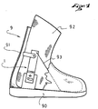
- the insert according to the invention is intended to equip a snowboard boot or boot 9 of the flexible type.
- the boot has a sole part 90, a rod part 91 of flexible material, an internal liner 92, preferably based on fabric or leather and padded flexible foam.
- the upper part is connected to the sole part by any means known from the state of the art such as by gluing, sewing, etc.
- the insert 1 is interposed between the internal liner 92 and the rest of the shoe. It is anchored by fixing means such as rivets, staples or the like on the sole portion 90 to immobilize it firmly inside the boot.
- the insert comprises a rigid, U-shaped base element 2, having an elongated plate-shaped base part 20 and extending upwards by two opposite lateral parts 21, 22. Each part 21, 22 forms with the base plate 20 at an angle close to 90 ° or slightly greater than 90 ° to take account of the particular shape of the base of the liner.
- the thickness of the element 2 is small, of the order of 2 to 5 mm approximately, but the element must be sufficiently rigid to withstand the various bending and torsional forces that it is brought to undergo.
- the base plate 20 is traversed by several bores 200, 201, 202 in order to be able to be fixed with an element of the sole part, preferably an internal reinforcement sole of metal or of fiber-based composite.
- the base plate is oriented transversely with respect to the longitudinal direction of the shoe represented in FIG. 2 by the line AR-AV.
- the length of the plate 20 must be substantially less than the width of the internal space of the sole of the shoe and slightly greater than the width of the boot, in order to be able to be inserted correctly.
- the opposite lateral parts 21, 22 take place on each side between the liner 92 and the upper 91 as shown in FIG. 1.
- Two lateral wings 3, 4 are each connected to one of the parts of lateral plates 21, 22 of the base element 2.
- each wing 3, 4 is able to pivot relative to the base element around the axis (I-I ') when the leg flexes in a longitudinal direction in the postero-anterior direction and vice versa.
- the wing 3 located on the internal side (INT) of the shoe is provided with a lower portion 30, and with an upper portion 31 connected together by a second articulation means 80 located above above the first means 50, substantially at ankle height.
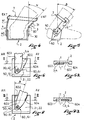
- This second means 80 allows the upper portion 31 to tilt laterally on the inside of the shoe when the leg bends laterally. The upper portion is therefore pushed by the lower leg which flexes inward above the ankle joint ( Figure 4).
- the other wing 4 on the external side is more rigid in lateral bending than the wing 3 situated on the internal side (INT).
- the wing 4 provides greater external lateral support which can be sought in the practice of snowboarding in order to be able to promote recovery.
- the higher rigidity of the wing 4 only moderately affects the movement in internal bending of the wing 3 insofar as the construction of the shoe upper is flexible and deformable.
- this second articulation means 80 consists of a thickness reduction zone separating the two portions over the entire width of the lateral wing 3.
- the insert also includes stop means 60, 61 which block the tilting or the antero-posterior inclination of the wings 3, 4 during a rear leg support and which also serves as a means of controlling the amplitude. tilting or tilting around (I-I ') to limit the maximum tilt ⁇ forward during the postero-anterior flexion of the leg ( Figure 5).
- This stop and control means 60, 61 consists of an oblong hole 600 which crosses the lower portion 30, 40 of each lateral wing 3, 4 and a lug 601 engaged with said oblong hole 600 which is fixed relative to the side part 21, 22.
- Figure 3 shows in detail the connection between the base element 20 and one of the wings 3.
- the lug 601 comprises a rod part riveted at one end to the side plate part 21 and a shoulder head at the other end for holding the lug in the oblong hole, even in the event of significant lateral deflection of the wing 3.
- the insert also comprises a flexible and inextensible rear support means 7 consisting of a connection element of the collar or strap type, each end 70, 71 of which is connected to one of the upper portions 31, 41 of the lateral wings 3 , 4 and which surrounds the calf.
- the flexible nature of the insert allows the deformation of the insert to be supported during lateral bending, without creating any discomfort zone for the lower leg.
- the difference in inclination created between the inner wing 3 provided with the articulation means 80 and the external wing 4 without articulation means is easily absorbed by the flexible rear support means 7.
- this means must be inextensible, or at least very little extensible to provide effective rear support.
- a means will be chosen in a flexible band or strap of small width in textile, leather or plastic for example.
- the connection with the wings 3, 4 is made by any known means allowing the articulation such as a rivet, for example.
- FIGS. 6, 6A, 7 and 7A show a variant of the invention with means for stopping and controlling the tilting amplitude of the wings 60, 61 which are different in their design.
- each lateral wing 3, 4 is articulated on each respective lateral part 21, 22 of the base element 2 by an articulation means 50, 51.
- the lower part 30, 40 of each wing is housed in a recess 602 formed in each lateral part.
- the recess includes a rear edge 603 on which the rear edge of the lower part of the wing rests to provide rear support when the wing is slightly tilted backwards (AR) (FIGS. 6 and 6A).
- the recess also includes a front edge 604 on which the front edge of the lower part of the wing rests to stop the race within the limit of angle of inclination ⁇ fixed (FIGS. 7 and 7A).
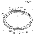
- the insert can be easily integrated into a construction of a shoe or boot of the flexible type, which includes an internal liner made of flexible foam, for example, a rod 91 formed of several flexible layers 910, 920.
- the wings 3, 4 of the insert are housed in a pocket between the inner layer 910 and the outer layer 920 of the rod.
- the pockets are closed by sewing, welding 922 or any other means of the layers 910, 920 between them.
- the movement of the wings causes a general deformation of the flexible structure of the shoe.
- FIG. 8 also shows that each lateral wing 3, 4 has a low inertia along the axis AA conducive to lateral bending while the inertia along the axis BB is maximum to favor a resistant rear support even in the event of transfer of significant practitioner's weight backwards.
- the upper portions of the wings are not necessarily flat plates but may be slightly curved.
- the curve can be given to improve comfort but also to increase the stiffness in lateral flexion of the wings.
- the wings 3, 4 may ultimately have various general shapes substantially different from those shown by way of example. They can also be perforated, for example partially in the region of the upper portion to allow passage of the malleolus and avoid any problem of discomfort.
- the base element and the lateral wings which are articulated on this element are preferably made of a rigid or semi-rigid material made of reinforced or unreinforced plastic.
- the insert also comprises two wires or traction strips 93, 94 one of the ends of which is connected to one of the upper portions 31, 41 of the wings side 3, 4 and the other end is connected to a shoe element located near the forefoot.
Landscapes
- Health & Medical Sciences (AREA)
- General Health & Medical Sciences (AREA)
- Physical Education & Sports Medicine (AREA)
- Chemical & Material Sciences (AREA)
- Engineering & Computer Science (AREA)
- Composite Materials (AREA)
- Materials Engineering (AREA)
- Footwear And Its Accessory, Manufacturing Method And Apparatuses (AREA)
Applications Claiming Priority (2)
| Application Number | Priority Date | Filing Date | Title |
|---|---|---|---|
| FR9603009A FR2745692B1 (fr) | 1996-03-06 | 1996-03-06 | Insert pour chaussure destinee a la pratique du surf sur neige |
| FR9603009 | 1996-03-06 |
Publications (2)
| Publication Number | Publication Date |
|---|---|
| EP0793920A1 true EP0793920A1 (de) | 1997-09-10 |
| EP0793920B1 EP0793920B1 (de) | 2000-11-15 |
Family
ID=9490040
Family Applications (1)
| Application Number | Title | Priority Date | Filing Date |
|---|---|---|---|
| EP97102634A Expired - Lifetime EP0793920B1 (de) | 1996-03-06 | 1997-02-19 | Einsatzstück für Snowboardstiefel |
Country Status (4)
| Country | Link |
|---|---|
| EP (1) | EP0793920B1 (de) |
| AT (1) | ATE197535T1 (de) |
| DE (1) | DE69703506T2 (de) |
| FR (1) | FR2745692B1 (de) |
Cited By (11)
| Publication number | Priority date | Publication date | Assignee | Title |
|---|---|---|---|---|
| US6099018A (en) * | 1997-04-18 | 2000-08-08 | The Burton Corporation | Snowboard binding |
| US6325405B2 (en) | 1999-03-03 | 2001-12-04 | Shimano Inc. | Active highback system for a snowboard boot |
| FR2834910A1 (fr) * | 2002-01-18 | 2003-07-25 | Atomic Austria Gmbh | Fixation de planche de surf des neiges |
| US6631919B1 (en) | 2000-01-06 | 2003-10-14 | The Burton Corporation | Wing-shaped leg support for a highback |
| US6705633B2 (en) | 2001-11-21 | 2004-03-16 | The Burton Corporation | Interface for engaging a snowboard boot to a snowboard binding |
| US6739615B1 (en) | 1997-04-18 | 2004-05-25 | The Burton Corporation | Snowboard binding |
| EP1428446A1 (de) * | 2002-12-14 | 2004-06-16 | HEAD Sport AG | Snowboard-Stiefel |
| EP1447117A1 (de) * | 2003-02-11 | 2004-08-18 | Goodwell International Limited | Snowboardbindung |
| EP1199952A4 (de) * | 1999-06-02 | 2005-01-26 | Vans Inc | Sportschuh mit verbindungselement |
| US7503579B2 (en) * | 2004-01-30 | 2009-03-17 | Salomon S.A. | Device for retaining a foot or boot on a sports apparatus |
| US8016315B2 (en) | 2005-09-30 | 2011-09-13 | Flow Sports, Inc. | Modular binding for sports board |
Citations (4)
| Publication number | Priority date | Publication date | Assignee | Title |
|---|---|---|---|---|
| DE3622746A1 (de) * | 1986-07-07 | 1988-01-21 | Markus Laemmert | Bindung fuer monoski |
| EP0646334A1 (de) * | 1993-10-01 | 1995-04-05 | U.S.P. Unique Sports Products Marketing und Vertriebs GmbH | Snowboard-Stiefel |
| US5435080A (en) * | 1992-12-17 | 1995-07-25 | Meiselman; Jamie | Boot for snowboarding and the like |
| FR2719197A1 (fr) * | 1994-04-29 | 1995-11-03 | Salomon Sa | Chaussure pour sport de glisse. |
-
1996
- 1996-03-06 FR FR9603009A patent/FR2745692B1/fr not_active Expired - Fee Related
-
1997
- 1997-02-19 DE DE69703506T patent/DE69703506T2/de not_active Expired - Fee Related
- 1997-02-19 AT AT97102634T patent/ATE197535T1/de not_active IP Right Cessation
- 1997-02-19 EP EP97102634A patent/EP0793920B1/de not_active Expired - Lifetime
Patent Citations (4)
| Publication number | Priority date | Publication date | Assignee | Title |
|---|---|---|---|---|
| DE3622746A1 (de) * | 1986-07-07 | 1988-01-21 | Markus Laemmert | Bindung fuer monoski |
| US5435080A (en) * | 1992-12-17 | 1995-07-25 | Meiselman; Jamie | Boot for snowboarding and the like |
| EP0646334A1 (de) * | 1993-10-01 | 1995-04-05 | U.S.P. Unique Sports Products Marketing und Vertriebs GmbH | Snowboard-Stiefel |
| FR2719197A1 (fr) * | 1994-04-29 | 1995-11-03 | Salomon Sa | Chaussure pour sport de glisse. |
Cited By (23)
| Publication number | Priority date | Publication date | Assignee | Title |
|---|---|---|---|---|
| US6347805B1 (en) | 1997-04-18 | 2002-02-19 | The Burton Corporation | Interface for engaging a snowboard boot to a binding |
| US6739615B1 (en) | 1997-04-18 | 2004-05-25 | The Burton Corporation | Snowboard binding |
| US6099018A (en) * | 1997-04-18 | 2000-08-08 | The Burton Corporation | Snowboard binding |
| US6325405B2 (en) | 1999-03-03 | 2001-12-04 | Shimano Inc. | Active highback system for a snowboard boot |
| US6398246B1 (en) | 1999-03-03 | 2002-06-04 | Shimano Inc. | Active highback system for a snowboard boot |
| EP1199952A4 (de) * | 1999-06-02 | 2005-01-26 | Vans Inc | Sportschuh mit verbindungselement |
| US6631919B1 (en) | 2000-01-06 | 2003-10-14 | The Burton Corporation | Wing-shaped leg support for a highback |
| US6705633B2 (en) | 2001-11-21 | 2004-03-16 | The Burton Corporation | Interface for engaging a snowboard boot to a snowboard binding |
| US6722688B2 (en) | 2001-11-21 | 2004-04-20 | The Burton Corporation | Snowboard binding system |
| US6726238B2 (en) | 2001-11-21 | 2004-04-27 | The Burton Corporation | Snowboard binding |
| FR2834910A1 (fr) * | 2002-01-18 | 2003-07-25 | Atomic Austria Gmbh | Fixation de planche de surf des neiges |
| US7073809B2 (en) | 2002-01-18 | 2006-07-11 | Atomic Austria Gmbh | Snowboard binding |
| EP1428446A1 (de) * | 2002-12-14 | 2004-06-16 | HEAD Sport AG | Snowboard-Stiefel |
| EP1447117A1 (de) * | 2003-02-11 | 2004-08-18 | Goodwell International Limited | Snowboardbindung |
| US7232132B2 (en) | 2003-02-11 | 2007-06-19 | Goodwell International Ltd. | Snowboard binding |
| US7367579B2 (en) | 2003-02-11 | 2008-05-06 | Goodwell International Ltd. | Snowboard binding |
| US8172252B2 (en) | 2003-02-11 | 2012-05-08 | Flow Sports, Inc. | Snowboard binding |
| US8544870B2 (en) | 2003-02-11 | 2013-10-01 | Flow Sports, Inc. | Snowboard binding |
| US8752845B2 (en) | 2003-02-11 | 2014-06-17 | Flow Sports, Inc. | Snowboard binding |
| US7503579B2 (en) * | 2004-01-30 | 2009-03-17 | Salomon S.A. | Device for retaining a foot or boot on a sports apparatus |
| US8016315B2 (en) | 2005-09-30 | 2011-09-13 | Flow Sports, Inc. | Modular binding for sports board |
| US8371605B2 (en) | 2005-09-30 | 2013-02-12 | Flow Sports, Inc. | Modular binding for sports board |
| US8752857B2 (en) | 2005-09-30 | 2014-06-17 | Flow Sports, Inc. | Modular binding for sports board |
Also Published As
| Publication number | Publication date |
|---|---|
| DE69703506D1 (de) | 2000-12-21 |
| FR2745692B1 (fr) | 1998-05-29 |
| FR2745692A1 (fr) | 1997-09-12 |
| EP0793920B1 (de) | 2000-11-15 |
| ATE197535T1 (de) | 2000-12-15 |
| DE69703506T2 (de) | 2001-03-22 |
Similar Documents
| Publication | Publication Date | Title |
|---|---|---|
| EP1166668B1 (de) | Sportschuh mit einer an einer flexiblen Fersenkappe befestigten steifen Fersenkappe | |
| FR2791528A1 (fr) | Chaussure de sport a ossature souple | |
| EP0704174B1 (de) | Gleitsportschuh | |
| FR2745488A1 (fr) | Prothese reactive de pied | |
| EP0793920B1 (de) | Einsatzstück für Snowboardstiefel | |
| EP0242526B1 (de) | Skischuh | |
| EP0774218B1 (de) | Rollschuh | |
| EP0825892B1 (de) | Schuhbindungsvorrichtung für einen gleitschuh | |
| EP0753267B1 (de) | Schneegleitbrett mit einer Innenschale und einem schwenkbaren steifen Hinterteil | |
| EP0933100A1 (de) | Bindung für einen Schuh an einem Snowboard | |
| FR2654904A1 (fr) | Chaussure de ski en matiere plastique. | |
| EP1118360A1 (de) | Rückhaltevorrichtung für einen Schuh auf einem Sportgerät | |
| EP1358916A1 (de) | Schuh für Betreiben eines Gleitsport oder Snowboardbindung mit Klemmlappen | |
| EP2954797B1 (de) | Sportschuh | |
| EP2885993B1 (de) | Sportschuh | |
| FR2774302A1 (fr) | Dispositif de retenue d'une chaussure sur un engin de glisse ou de roulage | |
| EP0858818A1 (de) | Haltevorrichtung mit Fersenstütze für einen Schuh an einem Gleitbrett | |
| EP0664968B1 (de) | Schischuh mit angelenkten Schaftvorderteil | |
| EP2374513A1 (de) | Vorrichtung zur Aufnahme eines Fußes oder eines Schuhs auf einem Gleitgerät | |
| EP1327467A1 (de) | Vorrichtung zum Befestigen eines Schuhs auf einem Sportgerät | |
| EP1358917A1 (de) | Snowboardbindung | |
| EP0573389B1 (de) | Schischuh | |
| EP0436444B1 (de) | Skischuh aus Kunststoff | |
| EP1491240B1 (de) | Fuss- oder Schuhhaltevorrichtung | |
| FR2963727A1 (fr) | Ceinture a traverse deportee pour sac a dos |
Legal Events
| Date | Code | Title | Description |
|---|---|---|---|
| PUAI | Public reference made under article 153(3) epc to a published international application that has entered the european phase |
Free format text: ORIGINAL CODE: 0009012 |
|
| AK | Designated contracting states |
Kind code of ref document: A1 Designated state(s): AT CH DE IT LI |
|
| 17P | Request for examination filed |
Effective date: 19980302 |
|
| GRAG | Despatch of communication of intention to grant |
Free format text: ORIGINAL CODE: EPIDOS AGRA |
|
| 17Q | First examination report despatched |
Effective date: 20000125 |
|
| GRAG | Despatch of communication of intention to grant |
Free format text: ORIGINAL CODE: EPIDOS AGRA |
|
| GRAH | Despatch of communication of intention to grant a patent |
Free format text: ORIGINAL CODE: EPIDOS IGRA |
|
| GRAH | Despatch of communication of intention to grant a patent |
Free format text: ORIGINAL CODE: EPIDOS IGRA |
|
| GRAA | (expected) grant |
Free format text: ORIGINAL CODE: 0009210 |
|
| AK | Designated contracting states |
Kind code of ref document: B1 Designated state(s): AT CH DE IT LI |
|
| REF | Corresponds to: |
Ref document number: 197535 Country of ref document: AT Date of ref document: 20001215 Kind code of ref document: T |
|
| REG | Reference to a national code |
Ref country code: CH Ref legal event code: EP |
|
| REF | Corresponds to: |
Ref document number: 69703506 Country of ref document: DE Date of ref document: 20001221 |
|
| PGFP | Annual fee paid to national office [announced via postgrant information from national office to epo] |
Ref country code: CH Payment date: 20010104 Year of fee payment: 5 |
|
| ITF | It: translation for a ep patent filed | ||
| PGFP | Annual fee paid to national office [announced via postgrant information from national office to epo] |
Ref country code: AT Payment date: 20010221 Year of fee payment: 5 |
|
| PLBE | No opposition filed within time limit |
Free format text: ORIGINAL CODE: 0009261 |
|
| STAA | Information on the status of an ep patent application or granted ep patent |
Free format text: STATUS: NO OPPOSITION FILED WITHIN TIME LIMIT |
|
| 26N | No opposition filed | ||
| PG25 | Lapsed in a contracting state [announced via postgrant information from national office to epo] |
Ref country code: AT Free format text: LAPSE BECAUSE OF NON-PAYMENT OF DUE FEES Effective date: 20020219 |
|
| PG25 | Lapsed in a contracting state [announced via postgrant information from national office to epo] |
Ref country code: LI Free format text: LAPSE BECAUSE OF NON-PAYMENT OF DUE FEES Effective date: 20020228 Ref country code: CH Free format text: LAPSE BECAUSE OF NON-PAYMENT OF DUE FEES Effective date: 20020228 |
|
| REG | Reference to a national code |
Ref country code: CH Ref legal event code: PL |
|
| PG25 | Lapsed in a contracting state [announced via postgrant information from national office to epo] |
Ref country code: IT Free format text: LAPSE BECAUSE OF NON-PAYMENT OF DUE FEES Effective date: 20050219 |
|
| PGFP | Annual fee paid to national office [announced via postgrant information from national office to epo] |
Ref country code: DE Payment date: 20060216 Year of fee payment: 10 |
|
| PG25 | Lapsed in a contracting state [announced via postgrant information from national office to epo] |
Ref country code: DE Free format text: LAPSE BECAUSE OF NON-PAYMENT OF DUE FEES Effective date: 20070901 |