EP0793987A2 - Verfahren zur Entölung von einer Öl-Wasser-Emulsion unter Verwendung von belüfteten Lösungen in einem Koalesziermedium - Google Patents
Verfahren zur Entölung von einer Öl-Wasser-Emulsion unter Verwendung von belüfteten Lösungen in einem Koalesziermedium Download PDFInfo
- Publication number
- EP0793987A2 EP0793987A2 EP97102798A EP97102798A EP0793987A2 EP 0793987 A2 EP0793987 A2 EP 0793987A2 EP 97102798 A EP97102798 A EP 97102798A EP 97102798 A EP97102798 A EP 97102798A EP 0793987 A2 EP0793987 A2 EP 0793987A2
- Authority
- EP
- European Patent Office
- Prior art keywords
- oil
- emulsion
- water
- vessel
- aerated solution
- Prior art date
- Legal status (The legal status is an assumption and is not a legal conclusion. Google has not performed a legal analysis and makes no representation as to the accuracy of the status listed.)
- Withdrawn
Links
- 238000000034 method Methods 0.000 title claims abstract description 71
- 239000007764 o/w emulsion Substances 0.000 title claims abstract description 35
- 239000000839 emulsion Substances 0.000 claims abstract description 121
- XLYOFNOQVPJJNP-UHFFFAOYSA-N water Substances O XLYOFNOQVPJJNP-UHFFFAOYSA-N 0.000 claims abstract description 105
- 238000004581 coalescence Methods 0.000 claims abstract description 14
- 239000000463 material Substances 0.000 claims abstract description 14
- 239000011159 matrix material Substances 0.000 claims description 79
- 230000008569 process Effects 0.000 claims description 25
- 238000005273 aeration Methods 0.000 claims description 15
- 239000007788 liquid Substances 0.000 claims description 11
- 238000009826 distribution Methods 0.000 claims description 4
- 230000001965 increasing effect Effects 0.000 claims description 4
- 238000002156 mixing Methods 0.000 claims description 4
- 238000004891 communication Methods 0.000 claims description 3
- 230000000630 rising effect Effects 0.000 claims description 3
- 238000013508 migration Methods 0.000 claims description 2
- 230000005012 migration Effects 0.000 claims description 2
- 239000000654 additive Substances 0.000 claims 2
- 230000000996 additive effect Effects 0.000 claims 2
- 229920006395 saturated elastomer Polymers 0.000 claims 2
- 239000000126 substance Substances 0.000 claims 2
- 239000007762 w/o emulsion Substances 0.000 claims 1
- 239000000243 solution Substances 0.000 description 46
- 239000007789 gas Substances 0.000 description 32
- VNWKTOKETHGBQD-UHFFFAOYSA-N methane Chemical compound C VNWKTOKETHGBQD-UHFFFAOYSA-N 0.000 description 8
- 238000000926 separation method Methods 0.000 description 8
- 239000012530 fluid Substances 0.000 description 6
- 238000012856 packing Methods 0.000 description 6
- CURLTUGMZLYLDI-UHFFFAOYSA-N Carbon dioxide Chemical compound O=C=O CURLTUGMZLYLDI-UHFFFAOYSA-N 0.000 description 4
- 238000005188 flotation Methods 0.000 description 4
- 230000003190 augmentative effect Effects 0.000 description 3
- 230000008901 benefit Effects 0.000 description 3
- 230000000694 effects Effects 0.000 description 3
- 238000004519 manufacturing process Methods 0.000 description 3
- IJGRMHOSHXDMSA-UHFFFAOYSA-N Atomic nitrogen Chemical compound N#N IJGRMHOSHXDMSA-UHFFFAOYSA-N 0.000 description 2
- 238000013019 agitation Methods 0.000 description 2
- 239000003570 air Substances 0.000 description 2
- 229910002092 carbon dioxide Inorganic materials 0.000 description 2
- 239000001569 carbon dioxide Substances 0.000 description 2
- 239000004020 conductor Substances 0.000 description 2
- 230000006872 improvement Effects 0.000 description 2
- 239000003345 natural gas Substances 0.000 description 2
- 239000004033 plastic Substances 0.000 description 2
- 229920003023 plastic Polymers 0.000 description 2
- -1 polyethylene Polymers 0.000 description 2
- 229920000642 polymer Polymers 0.000 description 2
- 238000012360 testing method Methods 0.000 description 2
- 229920003169 water-soluble polymer Polymers 0.000 description 2
- 239000004698 Polyethylene Substances 0.000 description 1
- 239000004743 Polypropylene Substances 0.000 description 1
- 238000005276 aerator Methods 0.000 description 1
- 230000003750 conditioning effect Effects 0.000 description 1
- 238000010276 construction Methods 0.000 description 1
- 230000003247 decreasing effect Effects 0.000 description 1
- 238000013461 design Methods 0.000 description 1
- 238000006073 displacement reaction Methods 0.000 description 1
- 238000009299 dissolved gas flotation Methods 0.000 description 1
- 230000002708 enhancing effect Effects 0.000 description 1
- 238000007373 indentation Methods 0.000 description 1
- 238000002347 injection Methods 0.000 description 1
- 239000007924 injection Substances 0.000 description 1
- 238000005304 joining Methods 0.000 description 1
- 239000000203 mixture Substances 0.000 description 1
- 229910052757 nitrogen Inorganic materials 0.000 description 1
- 229920000573 polyethylene Polymers 0.000 description 1
- 238000000746 purification Methods 0.000 description 1
- 238000004064 recycling Methods 0.000 description 1
- 230000009467 reduction Effects 0.000 description 1
- 230000004044 response Effects 0.000 description 1
- 230000000284 resting effect Effects 0.000 description 1
- 239000007921 spray Substances 0.000 description 1
- 230000003068 static effect Effects 0.000 description 1
- 239000000725 suspension Substances 0.000 description 1
Images




Classifications
-
- B—PERFORMING OPERATIONS; TRANSPORTING
- B03—SEPARATION OF SOLID MATERIALS USING LIQUIDS OR USING PNEUMATIC TABLES OR JIGS; MAGNETIC OR ELECTROSTATIC SEPARATION OF SOLID MATERIALS FROM SOLID MATERIALS OR FLUIDS; SEPARATION BY HIGH-VOLTAGE ELECTRIC FIELDS
- B03D—FLOTATION; DIFFERENTIAL SEDIMENTATION
- B03D1/00—Flotation
- B03D1/14—Flotation machines
- B03D1/1431—Dissolved air flotation machines
-
- B—PERFORMING OPERATIONS; TRANSPORTING
- B01—PHYSICAL OR CHEMICAL PROCESSES OR APPARATUS IN GENERAL
- B01D—SEPARATION
- B01D17/00—Separation of liquids, not provided for elsewhere, e.g. by thermal diffusion
- B01D17/02—Separation of non-miscible liquids
- B01D17/0205—Separation of non-miscible liquids by gas bubbles or moving solids
-
- B—PERFORMING OPERATIONS; TRANSPORTING
- B01—PHYSICAL OR CHEMICAL PROCESSES OR APPARATUS IN GENERAL
- B01D—SEPARATION
- B01D17/00—Separation of liquids, not provided for elsewhere, e.g. by thermal diffusion
- B01D17/02—Separation of non-miscible liquids
- B01D17/0208—Separation of non-miscible liquids by sedimentation
- B01D17/0211—Separation of non-miscible liquids by sedimentation with baffles
-
- B—PERFORMING OPERATIONS; TRANSPORTING
- B01—PHYSICAL OR CHEMICAL PROCESSES OR APPARATUS IN GENERAL
- B01D—SEPARATION
- B01D17/00—Separation of liquids, not provided for elsewhere, e.g. by thermal diffusion
- B01D17/02—Separation of non-miscible liquids
- B01D17/0208—Separation of non-miscible liquids by sedimentation
- B01D17/0214—Separation of non-miscible liquids by sedimentation with removal of one of the phases
-
- B—PERFORMING OPERATIONS; TRANSPORTING
- B03—SEPARATION OF SOLID MATERIALS USING LIQUIDS OR USING PNEUMATIC TABLES OR JIGS; MAGNETIC OR ELECTROSTATIC SEPARATION OF SOLID MATERIALS FROM SOLID MATERIALS OR FLUIDS; SEPARATION BY HIGH-VOLTAGE ELECTRIC FIELDS
- B03D—FLOTATION; DIFFERENTIAL SEDIMENTATION
- B03D1/00—Flotation
- B03D1/02—Froth-flotation processes
- B03D1/028—Control and monitoring of flotation processes; computer models therefor
-
- B—PERFORMING OPERATIONS; TRANSPORTING
- B03—SEPARATION OF SOLID MATERIALS USING LIQUIDS OR USING PNEUMATIC TABLES OR JIGS; MAGNETIC OR ELECTROSTATIC SEPARATION OF SOLID MATERIALS FROM SOLID MATERIALS OR FLUIDS; SEPARATION BY HIGH-VOLTAGE ELECTRIC FIELDS
- B03D—FLOTATION; DIFFERENTIAL SEDIMENTATION
- B03D1/00—Flotation
- B03D1/14—Flotation machines
- B03D1/1481—Flotation machines with a plurality of parallel plates
-
- B—PERFORMING OPERATIONS; TRANSPORTING
- B03—SEPARATION OF SOLID MATERIALS USING LIQUIDS OR USING PNEUMATIC TABLES OR JIGS; MAGNETIC OR ELECTROSTATIC SEPARATION OF SOLID MATERIALS FROM SOLID MATERIALS OR FLUIDS; SEPARATION BY HIGH-VOLTAGE ELECTRIC FIELDS
- B03D—FLOTATION; DIFFERENTIAL SEDIMENTATION
- B03D1/00—Flotation
- B03D1/14—Flotation machines
- B03D1/24—Pneumatic
-
- C—CHEMISTRY; METALLURGY
- C02—TREATMENT OF WATER, WASTE WATER, SEWAGE, OR SLUDGE
- C02F—TREATMENT OF WATER, WASTE WATER, SEWAGE, OR SLUDGE
- C02F1/00—Treatment of water, waste water, or sewage
- C02F1/24—Treatment of water, waste water, or sewage by flotation
-
- B—PERFORMING OPERATIONS; TRANSPORTING
- B03—SEPARATION OF SOLID MATERIALS USING LIQUIDS OR USING PNEUMATIC TABLES OR JIGS; MAGNETIC OR ELECTROSTATIC SEPARATION OF SOLID MATERIALS FROM SOLID MATERIALS OR FLUIDS; SEPARATION BY HIGH-VOLTAGE ELECTRIC FIELDS
- B03D—FLOTATION; DIFFERENTIAL SEDIMENTATION
- B03D1/00—Flotation
- B03D1/14—Flotation machines
- B03D1/1493—Flotation machines with means for establishing a specified flow pattern
-
- C—CHEMISTRY; METALLURGY
- C02—TREATMENT OF WATER, WASTE WATER, SEWAGE, OR SLUDGE
- C02F—TREATMENT OF WATER, WASTE WATER, SEWAGE, OR SLUDGE
- C02F1/00—Treatment of water, waste water, or sewage
- C02F1/40—Devices for separating or removing fatty or oily substances or similar floating material
-
- C—CHEMISTRY; METALLURGY
- C02—TREATMENT OF WATER, WASTE WATER, SEWAGE, OR SLUDGE
- C02F—TREATMENT OF WATER, WASTE WATER, SEWAGE, OR SLUDGE
- C02F2101/00—Nature of the contaminant
- C02F2101/30—Organic compounds
- C02F2101/32—Hydrocarbons, e.g. oil
-
- C—CHEMISTRY; METALLURGY
- C02—TREATMENT OF WATER, WASTE WATER, SEWAGE, OR SLUDGE
- C02F—TREATMENT OF WATER, WASTE WATER, SEWAGE, OR SLUDGE
- C02F2101/00—Nature of the contaminant
- C02F2101/30—Organic compounds
- C02F2101/32—Hydrocarbons, e.g. oil
- C02F2101/325—Emulsions
-
- Y—GENERAL TAGGING OF NEW TECHNOLOGICAL DEVELOPMENTS; GENERAL TAGGING OF CROSS-SECTIONAL TECHNOLOGIES SPANNING OVER SEVERAL SECTIONS OF THE IPC; TECHNICAL SUBJECTS COVERED BY FORMER USPC CROSS-REFERENCE ART COLLECTIONS [XRACs] AND DIGESTS
- Y10—TECHNICAL SUBJECTS COVERED BY FORMER USPC
- Y10S—TECHNICAL SUBJECTS COVERED BY FORMER USPC CROSS-REFERENCE ART COLLECTIONS [XRACs] AND DIGESTS
- Y10S210/00—Liquid purification or separation
- Y10S210/05—Coalescer
Definitions
- This invention relates to a method and system for removing dispersed oil from an oil in water emulsion.
- the plates of separator systems of this type are preferably formed of oleophilic material to augment coalescence of the oil droplets.
- a method of removing dispersed oil from an oil in water emulsion includes the steps of dissolving gas in water to form an aerated solution.
- the oil in water emulsion is introduced into a treatment vessel in which is positioned an assembly of closely spaced matrix plates formed of oleophilic material, such as corrugated plates formed of PVC or poly-propylene plastic.
- the emulsion is caused to pass in contact with the plates.
- the aerated solution is introduced into the treatment vessel to intermingle with the emulsion.
- oil droplets coalesce on the plates into larger oil droplets.
- the aerated solution releases gas bubbles in the emulsion being treated, the bubbles attaching themselves to oil droplets.
- the buoyancy of the oil droplet is greatly enhanced so that the oil droplets more readily rise by flotation to the water surface where an oil/water interface is formed.
- a liquid level is maintained within the vessel, the oil droplets rising to the surface of the liquid level.
- the oil droplets accumulate on the liquid surface to form an oil phase.
- the method includes the step of extracting oil that accumulates in the oil phase on the oil liquid interface. Water, having substantially all of the entrained oil extracted from it, is separately removed from the vessel.
- the aerated solution is introduced into the treatment vessel in a manner to create turbulence in the emulsion, the turbulence causing oil droplets to impinge against the matrix plates to promote oil droplet coalescence, and turbulence further augments the attachment of gas bubbles to oil droplets to increase separation effectiveness.
- a system for removing dispersed oil from water in an oil emulsion that may be effectively employed for practicing the method of this invention includes (a) an aeration apparatus for dissolving a gas in water to provide an aerated solution; (b) a process vessel having an emulsion inlet, an aerated solution inlet in communication with the aeration apparatus, an oil outlet, and a water outlet; (c) a matrix of closely spaced oleophilic plates positioned within the process vessel and arranged to receive a commingled flow of emulsion and aerated solution introduced through the emulsion inlet, the oleophilic plates serving to enhance the coalescence of oil droplets from the emulsion and the gas bubbles being released from the aerated solution tending to adhere to the oil droplets to enhance the buoyancy thereof; (d) an interface level detector for maintaining a liquid level surface within the process vessel, the oil droplets migrating to the liquid level surface to form an oil phase on top of the water surface within
- a distribution compartment may be positioned within a lower portion of the process vessel in communication with the emulsion inlet where the emulsion and aerated solution are combined prior to contact with the oleophilic plate matrix.
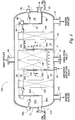
- Figure 1 is an elevational cross-sectional view of a horizontal cylindrical vessel showing one system for practicing the method of this invention.
- an emulsion inlet is provided adjacent one end of the vessel with a water outlet and an oil outlet adjacent the opposite end of the vessel and with an aerated solution inlet positioned intermediate the emulsion inlet and the water outlet.
- the emulsion fluid flow is through a horizontally arranged matrix of closely spaced oleophilic plates through which the emulsion passes vertically and a second matrix of closely spaced oleophilic plates through which the emulsion passes generally horizontally.
- Figure 2 is a first alternate embodiment of an apparatus for practicing the method of this invention.
- Figure 2 employs a horizontal cylindrical tank having an emulsion inlet intermediate the opposed ends of the tank with a water outlet adjacent each end of the tank.
- the apparatus of Figure 2 employs the method wherein an emulsion and an aerated solution are introduced into the interior of the vessel approximately midway between the opposed ends.
- the emulsion flows upwardly through vertically arranged closely spaced oleophilic plates, the emulsion flowing out of the oleophilic plates in directions towards both of the opposed ends of the vessel.
- a vertical assembly of plates through which the emulsion passes generally horizontally and, in like manner, towards the other end of the vessel is a similar vertical matrix of oleophilic plates through which the emulsion passes essentially horizontally.
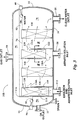
- Figure 3 is a second alternate embodiment of the invention in which aerated solution is commingled with the emulsion prior to introduction into the vessel and in which a separate aerated solution inlet is also employed adjacent the intermediate portion of the vessel between the two opposed ends.
- An important advantage of the embodiment of Figure 3 is that the emulsion is caused to flow first vertically through a vertically arranged matrix of oleophilic plates, then horizontally through vertically arranged plates, then again vertically through an assembly of plates and finally horizontally through an assembly of plates.
- the flow direction changes to help cause the oil droplets to separate from the flowing emulsion and to rise to the oil phase within the vessel, which floatation tendency is dramatically augmented by the introduction of aerated water into the vessel.
- Figure 4 is an elevational cross-sectional, more or less, diagrammatic view of an aerator that can be used for producing aerated solution employed in the method of the invention.
- Figure 5 is a diagrammatic representation of a preferred means of introducing a pressurized water stream into the emulsion.
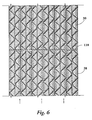
- Figure 6 is an enlarged fragmentary cross-sectional view of a matrix of closely spaced oleophilic plates as taken along the line 6-6 of Figure 1.
- Figure 7 shows similar oleophilic plates formed together in a matrix as they appear in cross-section and along the line 7-7 of Figure 2.
- Figure 8 is a similar cross-sectional arrangement of an oleophilic plate assembly as seen along the line 8-8 of Figure 3.
- Figure 9 illustrates the piping arrangement of a system for removing dispersed oil from an oil in water emulsion within a coalescing media employing a process vessel as illustrated in Figure 1.
- Figure 10 is a graph that plots oil concentration in an emulsion at four different sample point locations within a process vessel of the type such as shown in Figures 1 and 9 for different process condition.
- FIG. 1 an embodiment of the apparatus that may be employed in a system to practice the method of this invention is illustrated.
- the apparatus being in the form of a horizontal vessel 10 having a first end wall 12 and a second end wall 14.
- Formed in the bottom 16 of vessel 10 adjacent first end wall 12 is an emulsion inlet 18.
- Formed in bottom 16 adjacent second end wall 14 is a water outlet 20.
- An oil outlet 22 is formed in second end wall 14.
- a divider plate 24 Positioned internally of vessel 10 and intermediate ends 12 and 14 is a divider plate 24 having an upper edge 26. Positioned between divider plate 24 and vessel first end 12 is a matrix of closely spaced oleophilic plates. In the arrangement illustrated, a first matrix 28 is formed with an upper second matrix 30. Each matrix 28 and 30 is formed of a plurality of corrugated continuous plates formed of an oleophilic material such as PVC or polyethylene plastic. Each matrix is formed of the corrugated plates of the type that are commercially available from the National Tank Company whose home office is in Houston, Texas and sold under the trademark "PERFORMAX"®.
- the PERFORMAX plates are typically formed in a matrix in which the grooves in one plate run approximately 90° with respect to the grooves in the contiguous plate.
- the matrix is preferably organized so that the grooves extend at an angle of 45° with respect to the horizontal.
- the PERFORMAX plates provided with corrugations but also with spaced apart indentations to thereby provide surfaces affording increased opportunity for the impingement of oil droplets as the emulsion moves vertically through the plates.
- a spreader or diffuser 32 Positioned within the lower interior of vessel 10 between divider plate 24 and end wall 12 is a spreader or diffuser 32 having a plurality of openings 34.
- the emulsion flowing into the interior of vessel 10 through inlet 18 passes through diffuser 32 to thereby spread the flow of the emulsion upwardly in the vessel through first matrix 28 and second matrix 30 of oleophilic plates.
- an aerated solution inlet 36 Formed in bottom 16 of vessel 10 adjacent divider plate 24 is an aerated solution inlet 36.
- An important aspect of the method and apparatus herein disclosed is a means of enhancing the coalescence of oil droplets of the emulsion flowing through the oleophilic plates 28 and 30 that is achieved by augmenting the buoyancy of coalescenced oil droplets employing gas bubbles.
- an aerated solution is injected through either inlet 36 or emulsion inlet 18 to commingle with the emulsion to pass upwardly through the matrix of oleophilic plates.
- FIG. 4 illustrates an apparatus that can be used to provide an aerated solution.
- an aeration column generally indicated by the numeral 38 is illustrated.
- the illustrated aeration column is a vertically cylindrical vessel having a bottom 40 and top 42.
- a water inlet 44 and gas inlet 46 are provided in top 42.
- a perforated packing support 48 that divides the vessel into an upper interior portion 50 and a lower interior portion 52.
- packing rings Positioned within upper portion 50 and resting on the perforated packing support 48 are packing rings, such as commercially available Pal Rings - a type of packing frequently used in process vessels, particularly in the oil and gas industry or in any environment in which commingling of gas in liquid needs to be enhanced.
- a water outlet 52 having a valve 54 (or 70) that functions in response to a level detector 56 which, by way of illustration, includes, as a part thereof, a float 56A to thereby maintain an aerated water level 58 within the vessel lower interior portion 52.
- Water is introduced into the vessel through inlet 44 and passes through spray nozzle 60.
- Gas pressure is maintained within vessel 38 by gas injected into the vessel through gas inlet 46.
- the gas may be air, carbon dioxide, nitrogen, natural gas, methane, etc.
- the gas is dissolved and absorbed by the water.
- the water passes downwardly through packing 62 and perforated packing support 48 into the vessel lower portion 52.
- the water within lower interior portion 52 is aerated and the water is withdrawn from vessel 38 through outlet 52 and conveyed to aerated solution inlet 36 of the treatment vessel of Figure 1.
- FIG. 5 is a diagrammatic illustration of a method of mixing an aerated solution with an emulsion.
- Emulsion is injected through pipe 64 having a 90° bend 66 therein.
- a smaller diameter line 68 is positioned within pipe 64 at bend 66.
- An aerated solution that is, water containing dissolved gas, is injected through pipe 68 as controlled by valve 70, the gas bubbles form due to the pressure drop created by valve 70, the bubbles being dispersed within the emulsion stream.
- Outlet 72 thus provides an aerated emulsion stream to pass into inlet 18 in the vessel of Figure 1.
- portion 74 of pipe 64 extends just past elbow 66.
- the apparatus of Figure 5 serves as an intermediate between aeration tower 38 of Figure 4 and emulsion inlet 18 of vessel 10.
- Valve 54 of Figure 4 and valve 70 of Figure 5 can be one and the same.
- the aerated solution passes upwardly through first matrix 28 and second matrix 30 as it is commingled with the upwardly flowing emulsion stream.
- the aerated solution has a dramatic effect on the removal of the oil component from the emulsion.
- small droplets of the entrained oil form. These small droplets will stay in suspension unless and until the buoyancy of the droplets is sufficient to cause the droplets to move upwardly through the water filling the vessel to the oil/water interface 76.
- the vessel is filled with water 78, the water level being controlled by an interface detector 80 which, in turn, controls a valve (not shown) that regulates the passage of water out of vessel 10 through water outlet 20.
- an interface detector 80 which, in turn, controls a valve (not shown) that regulates the passage of water out of vessel 10 through water outlet 20.
- Above oil/water interface 76 is a layer of oil 82.
- Oil accumulates it passes over the top edge 84 of a vertical plate 86 which together with a lower plate 88 form an oil compartment 90 within the interior of vessel 10.
- the top edge 84 functions as a weir.
- Oil collected in oil compartment 90 is maintained at a level 92 by means of a level detector 94 that controls a valve (not shown) in series with oil outlet 22.
- the upward migration of the aerated solution introduced into vessel 10 through inlet 36 significantly augments separation of oil from the emulsion.
- droplets of oil form in matrix 28 and 30
- droplets are contacted by the aerated solution which carries small gas bubbles as a part thereof. These gas bubbles tend to attach themselves to the small oil droplets to greatly increase the buoyancy of the oil droplets to cause them to more readily pass upwardly through water 78 within the vessel and pass through the oil/water interface 76.
- the aerated solution provides a further improvement in the separation of oil from water within vessel 10 in that the aerated solution helps agitate the emulsion as it flows upwardly through matrix 28 and 30. This agitation is achieved by the effect of the gas bubbles entrained in the aerated solution as they aggressively move upwardly through the fluid within the vessel. The effect of this agitation is to increase the contact of the emulsion with the surfaces of the oleophilic plates to thereby more readily induce coalescence of oil contained in the emulsion.
- the entrained gas contained in the aerated solution passes upwardly through water 78, through the oil/water interface 76, and oil 82 into the upper portion 96 of the carrier of vessel 10, the upper portion 96 being above all fluid levels, and the gas ultimately passes out of the vessel through a gas outlet 98.
- the outlet gas may be recycled, such as back into gas inlet 46 of aeration column 38 as shown in Figure 4.
- a third matrix 100 of closely spaced paralleled corrugated oleophilic plates Positioned within the interior of vessel 10 between divider plate 24 and end wall 14 is a third matrix 100 of closely spaced paralleled corrugated oleophilic plates.
- the emulsion after having passed through matrix 28 and 30 in a vertical upward path and having passed over upper edge 26 of divider plate 24, flows generally horizontal through third matrix 100 where a third opportunity for coalescence takes place.
- the emulsion having substantially all of the oil components removed after flowing through a third matrix 100 flows out of the vessel through water outlet 20.
- FIG 2 an alternate system is illustrated for practicing the method of this invention wherein components similar to those of Figure 1 are assigned the same element number.
- a basic difference between the system of Figure 2 and that of Figure 1 is that in Figure 2 the emulsion after having entered emulsion inlet 18 flows generally horizontally in diverse directions toward first end wall 12 and second end wall 14 of vessel 10A.
- matrix 28 and 30 are each arranged vertically rather than horizontally.
- first matrix is designated by the numeral 28A and second matrix by the numeral 30A.
- Figure 2 adds a second divider plate 102 spaced parallel to the first divider plate 24, the second divider plate 102 providing an upper edge 104 over which the emulsion flows after having passed through matrix 30.
- a fourth matrix 106 is vertically positioned between second divider plate 102 and vessel end wall 12 through which the emulsion passes prior to exiting from the vessel through a second water outlet 20A.
- a second vertical plate 86A and lower plate 88A provide for a second oil compartment 90A that communicates with a second oil outlet 22A. The level of oil in the second compartment 90A is controlled by a second level detector 94A.
- the advantage of the system of Figure 2 is that it enables a vessel of the size comparable to the vessel of Figure 1 to handle a greater volume of emulsion.
- the principal of operation of the system of Figure 2 is the same as Figure 1, that is, the aerated solution passing upwardly through matrix 28 and 30 augments the separation of entrained oil by adding turbulence and buoyancy to oil droplets.
- FIG. 7 A cross-sectional view of matrix 28A and 30A is shown in Figure 7. While two matrixes 28A and 30A are employed with a dividing line 108. However, the dividing line 108 does not indicate an impervious surface as the ends of each matrix is open for fluid passage. The function of the system would be the same if matrixes 28A and 30A were one matrix of double thickness.
- The, dividing line 108 is indicative of the fact that in the practicalities of manufacturing, the matrixes, formed of closely spaced parallel plates of corrugated oleophilic material, are preferably formed in sections of selected thickness and the sections can be joined together in manufacturing a coalescing system.
- the dividing line 110 does not represent an impervious line but, in the contrary, merely a separation of one matrix from another wherein fluid freely flows without restriction.
- FIG 3 illustrates a third system for practicing the method of this invention utilizing vessel 10B similar to that of Figures 1 and 2 but wherein the internal arrangement is different.
- Emulsion inlet 112 has a different function in the embodiment of Figure 3 than the emulsion inlets in Figures 1 and 2, that is, in the arrangement of Figure 3 the emulsion is commingled with an aerated solution before introduction Into vessel 10B.
- the commingling of the emulsion and aerated solution can be obtained by joining the flow of the emulsion from outlet pipe 52 of aeration column 38, as shown in Figure 4, or from outlet end 72 of pipe 74 as shown in Figure 5.
- a first plate 114 is positioned adjacent end wall 12, the plate extending from vessel bottom 16.
- Plate 114 has an upper end 116 that functions as a weir over which oil flows into oil compartment 90 and ultimately out the oil outlet 22.
- a second plate 118 extends from the vessel bottom 16 but has an upper edge 118A that is spaced well below oil/water interface 76.
- a third plate 120 has a lower end that is above vessel bottom 16 and a top end that extends within but below the surface of oil phase 82. Fluid passing horizontally through the vessel flows underneath the lower end 120A of plate 120.
- a fourth plate 122 is like plate 118, that is, it extends from vessel bottom 16 and has a top edge 122A that is substantially below the oil/water interface 76.
- the emulsion After passing through second matrix 126, the emulsion must then flow under the lower edge 120A of plate 120, and the emulsion then flows upwardly through a third matrix 128.
- Aerated solution is introduced into the interior of vessel 10B through opening 36 that is directly positioned below third matrix 128.
- the emulsion passes upwardly within the third matrix it is commingled with the aerated solution to augment the separation of oil droplets as previously described, the oil droplets passing upwardly through the matrix into oil phase 82.
- the emulsion, passing out of third matrix 128, passes over top 122A of plate 122 and flows generally horizontally through a fourth matrix 130 where any remaining oil droplets are coalesced and passed upwardly by buoyancy, augmented by small gas bubbles that adhere thereto into oil phase 82.
- Water, being substantially free of entrained oil, is then removed from the vessel through water outlet 20.
- the level of water is maintained by an interface detector 80 in the same way as employed in Figures 1 and 2.
- An advantage of the arrangement of Figure 3 is that it provides a flow path by which emulsion twice passes vertically upwardly through vertically arranged corrugated coalescing plates and twice passes generally horizontally through vertically arranged corrugated coalescing plates. Further, the arrangement of Figure 3 uses an aerated solution in two different ways, that is, first when commingled with the emulsion as it passes initially into the vessel through inlet 112 and second, when the aerated solution is separately introduced through inlet 36.
- the embodiments illustrated in Figures 1, 2 and 3 are exemplary of the many different geometrical arrangements that can be achieved to practice the method of the invention.
- Figure 8 is a cross-sectional view of third matrix 128 as positioned between plates 120 and 122.
- Figure 9 illustrates a complete system for practicing the methods of this invention.
- the system of Figure 9 employs the process vessel 10 that has been described in detail with reference to Figure 1.
- Emulsion flows into the system through pipe 132 and can take one of two or a combination of routes. If valve 134 is open, the emulsion follows a first route and enters inlet 44 of aeration column 38 and is aerated as previously described with reference to Figure 4. Gas, such as air, carbon dioxide, natural gas, methane, etc., is supplied by way of pipe 136.
- An alternate, second route for the flow of emulsion from pipe 132 is through valve 138 (when opened) and then pipe 140 to the inlet 64 of the aeration apparatus of the type described with reference to Figure 5.
- the emulsion is aerated within the 90° bend formed by pipe 64, 74 and passes into inlet 18 of process vessel 10.
- valve 134 If valve 134 is closed, recycled water can pass by way of conduit 142 from the process vessel water outlet 20 through a positive displacement pump 144 and valve 146 to water inlet 44 of aeration column 38.
- Aerated water from outlet 52 of aeration column 38 flows by way of pipe 148 and valves 150 and 70 into inlet pipe 66 to inject aerated water into the emulsion.
- valve 70 functions to control the level of aerated water within the lower portion of aeration column 38
- valve 150 can be used in coordination with valves 134 and 138 to control the ratio of aerated water and emulsion that is passed into process vessel 10 through emulsion inlet 18.
- an alternative arrangement includes injecting all or a portion of the aerated water through aerated solution inlet 36. If all of the aerated water is to pass through aerated inlet 36, valve 150 is fully closed and valve 154 is open. A level control valve 156 is in series with valve 154 and is controlled by an electrical signal supplied by conductors 152. Thus, if valve 150 is closed and valve 154 is open, the level of aerated water within the lower portion of aeration column 38 is determined by control valve 156.
- the system of Figure 9 shows one means of integrating the components as disclosed herein for practicing the method of removing dispersed oil from an oil in water emulsion within a coalescing media. Further, Figure 9 shows that a series of options exist for routing aerated water and the emulsion and for commingling the aerated water and emulsion prior to injection into the process vessel or the commingling of the emulsion and aerated water can take place within the vessel, or a combination of these two methods can be employed.
- Figure 10 illustrates the improved results of separation of entrained oil in an emulsion under four different combination of elements as employed in the process vessel.
- the graph plots oil concentration versus sample point locations within a process vessel such as the type illustrated in Figure 1.
- Line 1 shows the results of the system wherein no matrix plates and no aerated water are employed when treating an emulsion having initially 550 parts per million (ppm) of oil. The result is a reduction at the outlet 20 of vessel 10 wherein entrained oil has been reduced from 550 ppm to about 110 ppm, a removal efficiency of 80.7%.
- Line 2 shows the use of an aerated solution but without the use of matrix plates. In line 2 the original emulsion contained about 725 ppm and the water discharged at the vessel outlet contained about 70 ppm, a removal efficiency of 90.6%.
- Line 3 shows the system with the use of matrix plates but without the use of aerated water wherein an emulsion having an initial 500 ppm resulted in water outlet of approximately 31 ppm, a removal efficiency of 93.8%.
- line 4 shows the system wherein both matrix plates and aerated water are employed and in which the emulsion initially having 500 ppm produced water at the vessel outlet 20 having only 24 ppm, a removal efficiency greater than 95%.
- the difference in performance between the four cases increases with increasing inlet oil concentration.
Landscapes
- Engineering & Computer Science (AREA)
- Chemical & Material Sciences (AREA)
- Life Sciences & Earth Sciences (AREA)
- Biotechnology (AREA)
- Physics & Mathematics (AREA)
- Thermal Sciences (AREA)
- Chemical Kinetics & Catalysis (AREA)
- General Engineering & Computer Science (AREA)
- Hydrology & Water Resources (AREA)
- Environmental & Geological Engineering (AREA)
- Water Supply & Treatment (AREA)
- Organic Chemistry (AREA)
- Physical Water Treatments (AREA)
Applications Claiming Priority (2)
| Application Number | Priority Date | Filing Date | Title |
|---|---|---|---|
| US611413 | 1996-03-05 | ||
| US08/611,413 US5656173A (en) | 1996-03-05 | 1996-03-05 | Method of removing dispersed oil from an oil in water emulsion employing aerated solutions within a coalescing media |
Publications (2)
| Publication Number | Publication Date |
|---|---|
| EP0793987A2 true EP0793987A2 (de) | 1997-09-10 |
| EP0793987A3 EP0793987A3 (de) | 1997-12-29 |
Family
ID=24448921
Family Applications (1)
| Application Number | Title | Priority Date | Filing Date |
|---|---|---|---|
| EP97102798A Withdrawn EP0793987A3 (de) | 1996-03-05 | 1997-02-20 | Verfahren zur Entölung von einer Öl-Wasser-Emulsion unter Verwendung von belüfteten Lösungen in einem Koalesziermedium |
Country Status (4)
| Country | Link |
|---|---|
| US (1) | US5656173A (de) |
| EP (1) | EP0793987A3 (de) |
| CA (1) | CA2198325A1 (de) |
| NO (1) | NO970948L (de) |
Cited By (3)
| Publication number | Priority date | Publication date | Assignee | Title |
|---|---|---|---|---|
| WO2007049244A1 (en) * | 2005-10-28 | 2007-05-03 | M-I Epcon As | A gravity separator, and a method for separating a mixture containing water, oil, and gas |
| FR2916196A1 (fr) * | 2007-05-18 | 2008-11-21 | Otv Sa | Installation de traitement d'eau par flottation, et procede de traitement d'eau correspondant |
| CN104016520A (zh) * | 2014-06-18 | 2014-09-03 | 哈尔滨工业大学 | 一种气浮耦合混凝预处理煤化工废水的装置及利用该装置预处理煤气化废水的方法 |
Families Citing this family (50)
| Publication number | Priority date | Publication date | Assignee | Title |
|---|---|---|---|---|
| FI104851B (fi) * | 1997-02-18 | 2000-04-14 | Safematic Oy | Sovitelma kiertovoitelujärjestelmän yhteydessä |
| US5988283A (en) * | 1997-07-02 | 1999-11-23 | Union Pacific Resources Company | Vertical combined production facility |
| US6074557A (en) * | 1998-02-02 | 2000-06-13 | Lyles, Sr.; Robert G. | Water treatment device and method |
| US6187079B1 (en) | 1998-05-17 | 2001-02-13 | Baker Hughes Incorporated | Three-phase separator |
| CA2251208A1 (en) * | 1998-11-12 | 2000-05-12 | Claude Perreault | Fully automatic plating wax collecting device and method thereof |
| AU2000238310A1 (en) * | 2000-04-06 | 2001-10-23 | Lisopharm Ag | Method and apparatus for separation of a mixture of non-miscible liquids |
| US6482322B1 (en) * | 2000-04-26 | 2002-11-19 | Robert C. Tsigonis | Apparatus and method for treating sewage in cold climates |
| AU2002211546A1 (en) * | 2000-10-13 | 2002-04-22 | Micell Technologies, Inc. | Device and process for dry-cleaning process using carbon dioxide and a divided pressure vessel |
| DE60234314D1 (en) | 2001-02-16 | 2009-12-24 | Stone & Webster Process Tech | Quenchwasservorbehandlungsverfahren |
| US7157007B2 (en) * | 2003-06-20 | 2007-01-02 | National Tank Company | Vertical gas induced flotation cell |
| US7879229B2 (en) * | 2003-10-29 | 2011-02-01 | Zenon Technology Partnership | Water treatment plant with immersed membranes |
| US8114293B2 (en) * | 2003-10-29 | 2012-02-14 | Zenon Technology Partnership | Method of operating a water treatment plant with immersed membranes |
| FI116611B (fi) * | 2004-06-10 | 2006-01-13 | Outokumpu Oy | Menetelmä ja laitteisto vesiliuoksiin niukkaliukoisen orgaanisen liuoksen puhdistamiseksi vesiliuosjäänteistä |
| FI116610B (fi) * | 2004-06-10 | 2006-01-13 | Outokumpu Oy | Menetelmä ja laitteisto vesiliuoksen puhdistamiseksi uuttoaineliuospisaroista |
| US8080158B2 (en) | 2005-11-22 | 2011-12-20 | Exterran Water Solutions Ulc | Vessel and method for treating contaminated water |
| NO330765B1 (no) * | 2006-03-15 | 2011-07-11 | Hamworthy Plc | Tank for behandling av fluider og system for prosessering av bronnfluider omfattende en slik tank |
| US7628919B2 (en) * | 2006-09-01 | 2009-12-08 | Anticline Disposal, Llc | Method for treating water contaminated with methanol and boron |
| US8105488B2 (en) | 2006-09-01 | 2012-01-31 | Anticline Disposal, Llc | Waste water treatment method |
| US7510656B2 (en) * | 2006-09-01 | 2009-03-31 | Anticline Disposal, Llc | Waste water treatment method |
| US7527736B2 (en) * | 2006-09-01 | 2009-05-05 | Anticline Disposal, Llc | Method for generating fracturing water |
| US8133396B2 (en) * | 2007-01-11 | 2012-03-13 | Smith & Loveless, Inc. | Dissolved air floatation with filter system |
| WO2010028117A1 (en) | 2008-09-03 | 2010-03-11 | Cummins Filtration Ip Inc. | Air-jacketed coalescer media with improved performance |
| US9199185B2 (en) * | 2009-05-15 | 2015-12-01 | Cummins Filtration Ip, Inc. | Surface coalescers |
| US8360251B2 (en) | 2008-10-08 | 2013-01-29 | Cummins Filtration Ip, Inc. | Multi-layer coalescing media having a high porosity interior layer and uses thereof |
| US8590712B2 (en) * | 2008-10-08 | 2013-11-26 | Cummins Filtration Ip Inc. | Modular filter elements for use in a filter-in-filter cartridge |
| US8517185B2 (en) * | 2008-10-08 | 2013-08-27 | Cummins Filtration Ip, Inc. | Two stage fuel water separator and particulate filter utilizing pleated nanofiber filter material |
| BR112012007945A2 (pt) | 2009-11-16 | 2016-03-22 | Cummins Filtration Ip Inc | sistemas coalescentes |
| CN102946966B (zh) | 2010-06-22 | 2016-01-27 | 康明斯过滤Ip公司 | 二级燃料水分离器及粒子过滤器 |
| US9334175B2 (en) * | 2010-07-02 | 2016-05-10 | 1501367 Alberta Ltd. | Method and apparatus for treatment of fluids |
| EP2397207A1 (de) * | 2011-02-08 | 2011-12-21 | Shell Internationale Research Maatschappij B.V. | System zum Trennen eines Zufuhrstroms mit mindestens drei Flüssigkeitsphasen |
| US8834724B1 (en) | 2011-03-16 | 2014-09-16 | Enviro-Tech Systems, L.L.C. | Method and apparatus for separation of fluids by means of induced gas flotation and advances in said technology |
| US20130062288A1 (en) * | 2011-09-12 | 2013-03-14 | Wayne W. Spani | Programmable fluid treatment system and method |
| CA2849290A1 (en) | 2011-09-22 | 2013-03-28 | Chevron U.S.A. Inc. | Apparatus and process for treatment of water |
| US9719179B2 (en) | 2012-05-23 | 2017-08-01 | High Sierra Energy, LP | System and method for treatment of produced waters |
| US10058808B2 (en) | 2012-10-22 | 2018-08-28 | Cummins Filtration Ip, Inc. | Composite filter media utilizing bicomponent fibers |
| CN103408153B (zh) * | 2013-07-29 | 2015-06-24 | 常州大学 | 含乳化油污水物理破乳处理装置及其处理方法 |
| US9433878B2 (en) | 2013-10-31 | 2016-09-06 | General Electric Company | Electrostatic coalescer for coalescing a dispersed phase from a continuous phase in an emulsion |
| US9573079B2 (en) | 2013-10-31 | 2017-02-21 | General Electric Company | Article and apparatus for enhancing the coalescence of a dispersed phase from a continuous phase in an emulsion |
| US9512014B2 (en) * | 2014-08-06 | 2016-12-06 | Cameron Solutions, Inc. | Water treating equipment providing coalescence and flotation within a single vessel |
| RU2622774C2 (ru) * | 2015-11-26 | 2017-06-20 | Публичное акционерное общество "Газпром" | Способ разделения несмешивающихся жидкостей разной плотности и устройство для его осуществления |
| US10456714B2 (en) * | 2016-02-24 | 2019-10-29 | William Jacob Management, Inc. | Multi-purpose gas separator unit |
| WO2018017701A1 (en) | 2016-07-19 | 2018-01-25 | Cummins Filtration Ip, Inc. | Perforated layer coalescer |
| US9969944B2 (en) | 2016-09-23 | 2018-05-15 | Janus Technology Solutions, LLC | Dissolved oil removal from quench water of gas cracker ethylene plants |
| CN106477670B (zh) * | 2016-11-04 | 2023-04-07 | 天津斯林力克密封科技有限公司 | 一种含油乳化污水破乳装置 |
| WO2018112004A1 (en) | 2016-12-13 | 2018-06-21 | Air & Liquid Systems Inc. | Animal byproduct recovery system |
| CN108502975B (zh) * | 2018-04-13 | 2020-04-07 | 宁波清智环保科技有限公司 | 生活废水再生处理系统 |
| CN109019737A (zh) * | 2018-09-11 | 2018-12-18 | 河南龙成煤高效技术应用有限公司 | 一种气浮除油装置以及气浮除油的方法 |
| KR102873862B1 (ko) * | 2018-12-12 | 2025-10-17 | 씨.씨.젠센에이/에스 | 오일로부터 물의 제거를 위한 시스템 |
| CA3090353C (en) | 2020-08-18 | 2026-01-06 | 1501367 Alberta Ltd. | Fluid treatment separator and a system and method of treating fluid |
| CN115340242B (zh) * | 2022-08-30 | 2023-04-18 | 宁波开诚生态技术股份有限公司 | 一种含油污水处理装置及处理工艺 |
Family Cites Families (23)
| Publication number | Priority date | Publication date | Assignee | Title |
|---|---|---|---|---|
| DE1213223C2 (de) * | 1960-02-15 | 1973-02-01 | Milos Krofta Dr Ing | Vorrichtung zum Reinigen der ungeklaerten Abwaesser in den Papier-, Zellstoff- und aehnlichen Industrien |
| GB1309930A (en) * | 1969-07-07 | 1973-03-14 | Pielkenrood Vinitex Bv | Separators for removing flotation and or precipitation components from a liquid |
| US3754656A (en) * | 1970-09-28 | 1973-08-28 | Kurita Water Ind Ltd | Floatation separators |
| US4133771A (en) * | 1972-04-25 | 1979-01-09 | Pielkenrood-Vinitex B.V. | Apparatus for bringing about particle growth in a flowing liquid suspension |
| US3957656A (en) * | 1972-04-28 | 1976-05-18 | Castelli Joseph L | Plate separator for fluid mixtures |
| GB1525606A (en) * | 1974-10-10 | 1978-09-20 | Pielkenrood Vinitex Bv | Purification devices |
| US4113629A (en) * | 1974-11-27 | 1978-09-12 | Pielkenrood-Vinitex B.V. | Separation device provided with a coalescence apparatus |
| US4231867A (en) * | 1979-08-31 | 1980-11-04 | Sutphin Eldon M | Method and apparatus for treating heterogeneous fluid systems |
| US4278545A (en) * | 1979-09-12 | 1981-07-14 | The Bendix Corporation | Apparatus for separating solids and liquid components |
| US4246112A (en) * | 1979-10-31 | 1981-01-20 | Ultracept, Inc. | Oil-water separator having means for conditioning the water for reuse |
| NL8100927A (nl) * | 1981-02-25 | 1982-09-16 | Pielkenrood Vinitex Bv | Werkwijze en inrichting voor het zuiveren van een vloeistof. |
| US4377485A (en) * | 1981-09-15 | 1983-03-22 | Lenox Institute For Research, Inc. | Apparatus and method for clarification of water using combined flotation and filtration processes |
| US4555332A (en) * | 1984-01-27 | 1985-11-26 | Combustion Engineering, Inc. | Treatment of oil well production |
| US4800025A (en) * | 1986-08-20 | 1989-01-24 | Pony Industries, Inc. | Apparatus and process for the gas flotation purification of oil-contaminated water |
| SU1397411A1 (ru) * | 1986-12-19 | 1988-06-15 | Брестский инженерно-строительный институт | Устройство дл очистки сточных вод |
| US4802978A (en) * | 1987-02-27 | 1989-02-07 | Mctighe Industries, Inc. | Oil-water separator |
| US4782789A (en) * | 1987-10-26 | 1988-11-08 | Eau Claire Systems Inc | Induced static flotation cell |
| US5320750A (en) * | 1988-09-07 | 1994-06-14 | Milos Krofta | Water clarifier with first filtrate isolation, improved backwashing and improved bubble generation |
| US5080802A (en) * | 1990-05-09 | 1992-01-14 | Cairo Jr John A | Induced gas liquid coalescer and flotation separator |
| US5156745A (en) * | 1990-05-09 | 1992-10-20 | Cairo Jr John A | Induced gas liquid coalescer and flotation separator |
| US5158678A (en) * | 1990-09-28 | 1992-10-27 | Broussard Paul C Sr | Water clarification method and apparatus |
| NO303048B1 (no) * | 1994-10-19 | 1998-05-25 | Mastrans As | FremgangsmÕte og utstyr for rensing av en vµske |
| US5516434A (en) * | 1995-05-26 | 1996-05-14 | Unicel, Inc. | Single cell gas flotation separator with filter media |
-
1996
- 1996-03-05 US US08/611,413 patent/US5656173A/en not_active Expired - Fee Related
-
1997
- 1997-02-20 EP EP97102798A patent/EP0793987A3/de not_active Withdrawn
- 1997-02-24 CA CA002198325A patent/CA2198325A1/en not_active Abandoned
- 1997-02-28 NO NO970948A patent/NO970948L/no not_active Application Discontinuation
Cited By (11)
| Publication number | Priority date | Publication date | Assignee | Title |
|---|---|---|---|---|
| WO2007049244A1 (en) * | 2005-10-28 | 2007-05-03 | M-I Epcon As | A gravity separator, and a method for separating a mixture containing water, oil, and gas |
| EP1782869A1 (de) * | 2005-10-28 | 2007-05-09 | M-I Epcon As | Schwerkraft-Abscheider. |
| EA013256B1 (ru) * | 2005-10-28 | 2010-04-30 | М-И Эпкон Ас | Гравитационный сепаратор и способ разделения смеси, содержащей воду, нефть и газ |
| US8088286B2 (en) | 2005-10-28 | 2012-01-03 | Schlumberger Norge As | Gravity separator, and a method for separating a mixture containing water, oil, and gas |
| FR2916196A1 (fr) * | 2007-05-18 | 2008-11-21 | Otv Sa | Installation de traitement d'eau par flottation, et procede de traitement d'eau correspondant |
| WO2008142026A1 (fr) * | 2007-05-18 | 2008-11-27 | Otv Sa | Installation de traitement d'eau par flottation, et procede de traitement d'eau correspondant |
| JP2010527286A (ja) * | 2007-05-18 | 2010-08-12 | オテヴェ・ソシエテ・アノニム | 浮上分離による水処理設備および水処理方法 |
| CN101711178B (zh) * | 2007-05-18 | 2012-09-12 | 威立雅水务解决方案与技术支持联合股份公司 | 采用浮选的水处理设备以及相应的水处理方法 |
| AU2008252988B2 (en) * | 2007-05-18 | 2012-12-06 | Veolia Water Solutions & Technologies Support | Flotation water treatment plant and corresponding water treatment method |
| US8753508B2 (en) | 2007-05-18 | 2014-06-17 | Veolia Water Solutions & Technologies Support | Installation for water treatment by flotation and corresponding water treatment method |
| CN104016520A (zh) * | 2014-06-18 | 2014-09-03 | 哈尔滨工业大学 | 一种气浮耦合混凝预处理煤化工废水的装置及利用该装置预处理煤气化废水的方法 |
Also Published As
| Publication number | Publication date |
|---|---|
| NO970948D0 (no) | 1997-02-28 |
| US5656173A (en) | 1997-08-12 |
| NO970948L (no) | 1997-09-08 |
| CA2198325A1 (en) | 1997-09-05 |
| EP0793987A3 (de) | 1997-12-29 |
Similar Documents
| Publication | Publication Date | Title |
|---|---|---|
| US5656173A (en) | Method of removing dispersed oil from an oil in water emulsion employing aerated solutions within a coalescing media | |
| US2766203A (en) | Water purification process and apparatus | |
| US4251361A (en) | Hybrid gas flotation separator | |
| KR101217363B1 (ko) | 수평 탱크들을 가스 부상 분리기들로 전환시키기 위한 방법 및 장치 | |
| US3558482A (en) | Water purification | |
| US6875351B2 (en) | Methods and apparatus for oil demulsification and separation of oil and suspended solids from produced water | |
| US3884803A (en) | Process for separating low api gravity oil from water | |
| US4198300A (en) | Apparatus for removing suspended oil droplets from water | |
| KR100559350B1 (ko) | 제2의 액에서 제1의 액을 분리하는 방법 | |
| EP1620194B1 (de) | Verfahren und vorrichtung zur öl-wasser-trennung. | |
| US4627922A (en) | Method of removing dissolved oil from produced water | |
| Stewart et al. | Produced water treatment field manual | |
| US20170088441A1 (en) | Method and device for deep oil removal from wastewater containing low concentration dirty oil | |
| US3986954A (en) | Method and apparatus for clarifying contaminated liquids | |
| US20020046977A1 (en) | Multi-directional flow gravity separator | |
| GB1154442A (en) | Shaped fibres and filtering apparatus comprising the same | |
| US5580463A (en) | Pressurized, sparged flotation column | |
| US4746440A (en) | Process and apparatus for the separation of emulsions or of solids from a suspension of solids and a liquid by means of pressure or turbo flotation | |
| EP0241167A1 (de) | Flotation, Verfahren und Vorrichtung zur Trennung von Fremdkörpern aus Flüssigkeiten | |
| US5543043A (en) | Clarification of produced water in the oil and gas industry | |
| US4173533A (en) | Method for removing suspended oil droplets from water | |
| US3873283A (en) | Vapor-liquid separator | |
| Osamor et al. | Oil/water Separation: State-of-the-art | |
| Moosai et al. | Oily wastewater cleanup by gas flotation | |
| CA2553219C (en) | Small droplets recovery system |
Legal Events
| Date | Code | Title | Description |
|---|---|---|---|
| PUAI | Public reference made under article 153(3) epc to a published international application that has entered the european phase |
Free format text: ORIGINAL CODE: 0009012 |
|
| AK | Designated contracting states |
Kind code of ref document: A2 Designated state(s): DE DK FR GB IT |
|
| PUAL | Search report despatched |
Free format text: ORIGINAL CODE: 0009013 |
|
| AK | Designated contracting states |
Kind code of ref document: A3 Designated state(s): DE DK FR GB IT |
|
| 17P | Request for examination filed |
Effective date: 19980623 |
|
| 17Q | First examination report despatched |
Effective date: 20000110 |
|
| GRAG | Despatch of communication of intention to grant |
Free format text: ORIGINAL CODE: EPIDOS AGRA |
|
| GRAG | Despatch of communication of intention to grant |
Free format text: ORIGINAL CODE: EPIDOS AGRA |
|
| GRAH | Despatch of communication of intention to grant a patent |
Free format text: ORIGINAL CODE: EPIDOS IGRA |
|
| STAA | Information on the status of an ep patent application or granted ep patent |
Free format text: STATUS: THE APPLICATION IS DEEMED TO BE WITHDRAWN |
|
| 18D | Application deemed to be withdrawn |
Effective date: 20001208 |