EP0794029B1 - Befestigung für einen Schweissbrenner - Google Patents
Befestigung für einen Schweissbrenner Download PDFInfo
- Publication number
- EP0794029B1 EP0794029B1 EP97101259A EP97101259A EP0794029B1 EP 0794029 B1 EP0794029 B1 EP 0794029B1 EP 97101259 A EP97101259 A EP 97101259A EP 97101259 A EP97101259 A EP 97101259A EP 0794029 B1 EP0794029 B1 EP 0794029B1
- Authority
- EP
- European Patent Office
- Prior art keywords
- stem
- housing
- torch
- wire
- attachment
- Prior art date
- Legal status (The legal status is an assumption and is not a legal conclusion. Google has not performed a legal analysis and makes no representation as to the accuracy of the status listed.)
- Expired - Lifetime
Links
- 238000003466 welding Methods 0.000 title claims abstract description 18
- 230000037431 insertion Effects 0.000 claims abstract description 5
- 238000003780 insertion Methods 0.000 claims abstract description 5
- 239000004020 conductor Substances 0.000 claims abstract description 3
- 244000273618 Sphenoclea zeylanica Species 0.000 claims description 2
- 239000002184 metal Substances 0.000 description 9
- 229910052751 metal Inorganic materials 0.000 description 9
- 239000000463 material Substances 0.000 description 6
- 229920003023 plastic Polymers 0.000 description 4
- 239000004033 plastic Substances 0.000 description 4
- 229910001369 Brass Inorganic materials 0.000 description 3
- 239000010951 brass Substances 0.000 description 3
- RYGMFSIKBFXOCR-UHFFFAOYSA-N Copper Chemical compound [Cu] RYGMFSIKBFXOCR-UHFFFAOYSA-N 0.000 description 2
- 229910052802 copper Inorganic materials 0.000 description 2
- 239000010949 copper Substances 0.000 description 2
- 238000004519 manufacturing process Methods 0.000 description 2
- 238000009413 insulation Methods 0.000 description 1
- 230000001681 protective effect Effects 0.000 description 1
Images

Classifications
-
- B—PERFORMING OPERATIONS; TRANSPORTING
- B23—MACHINE TOOLS; METAL-WORKING NOT OTHERWISE PROVIDED FOR
- B23K—SOLDERING OR UNSOLDERING; WELDING; CLADDING OR PLATING BY SOLDERING OR WELDING; CUTTING BY APPLYING HEAT LOCALLY, e.g. FLAME CUTTING; WORKING BY LASER BEAM
- B23K9/00—Arc welding or cutting
- B23K9/32—Accessories
- B23K9/323—Combined coupling means, e.g. gas, electricity, water or the like
Definitions
- the present invention relates to a connection system according to preamble of claim 1 and, more particularly, the female part of the attachment, of the type comprising a metal body provided with two or more electrical connectors, a connection for the gas supply and a stem for the connection of welding wire guiding devices, in which the said stem for the connection of the means of directing the wire is inserted into a hole formed in the said metal body and has a housing for the insertion of the relevant male connection present on the torch.
- the invention consists in a specific configuration of the parts which form the female part of the connector, so as to give the above-mentioned advantages in terms of use and practicality.
- the invention relates to the field of welding and, in particular, refers to attachments which allow a welding torch to be connected to the body of the welding machine.
- a female part which is attached to the frame of the machine and which comprises a metal body, generally in the form of a cylinder made of brass or other suitable material, provided on the outside with a threading on which is fixed the male connection of a torch and inserted inside an insulating casing, usually made of plastics material, which is attached to the wall of the welding machine.
- the invention relates to this "female" connector, that is that part which is fixed to the body of the welding machine..
- the female part is formed from a metal body which is generally cylindrical, for example of brass or copper, with a series of electrical contacts equipped with a suitable bushing, a connection for the gas supply and a stem with wire-guiding devices which leads to a housing in which is inserted the corresponding wire guide of the torch.
- US-A-4.582.976 shows a connection system, according to preamble of claim 1, to be applied to a robot, comprising a metal body 101, with electrical contacts and a gas feeding attachment 115, in which the wire supply devices comprise a stem 126 inserted into a hole of body 101 at a first end thereof, a tube 141 inserted into the hole of the body at a second end thereof, and a wire support liner 156.
- the aim of the invention is to propose a connector of the type described above, which is however lighter and smaller than those already known, easier and more economical to produce but which allows the connection of existing torches with standard attachments.
- the inside of the body of the female connection is made from plastics material, with the electrical contacts for the connection of the torch control cables being housed inside this.
- the outside part of the body is instead formed from a metal box which is threaded on one part for connection to the torch and which has, on the opposite side, attachments for the cables supplying the welding current.
- this solution does not give the same results as attachments already known, as it significantly reduces the conductive cross-section, thus limiting the amperage which the attachment is able to conduct.
- Another known solution which is also aimed at reducing the cost of the components, involves making the whole body of the attachment in plastics material and disposing in the body a metal box which forms the housing into which is inserted the wireguiding device of the torch. The stem with the wire-guiding sheath is fixed on the opposite side of the box.
- the cross-section of the metal part is reduced by a very significant measure, being practically limited to the box which forms an integral part of the stem, thus creating a limit to the welding current.
- the plastics thread is easily worn and subject to damage during impacts etc.
- the aim of the present invention is to eliminate the above mentioned disadvantages by creating an attachment for welding torches (and in particular the female part of the connector) which, although retaining the same characteristics of electrical conductivity, practicality and safety as the known attachments, is more economical to produce, significantly smaller and lighter.
- connection system in particular by forming the wire-guiding stem from a single piece with a box which forms the housing in which the wireguide on the torch is inserted, then inserting the stem with the box in a corresponding hole provided on the attachment.
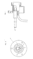
- the connector has a body 1, for example a cylindrical body made of brass, copper or other suitable conductive material, inserted inside a sleeve 2 with a flange 3 for fixing to the wall of the welding machine.
- the front of the body 1 has an external thread 4 which allows the male connector of the torch to be attached and the dimension of the sleeve 3 is larger than that of this zone, so that it forms a type of protective cover 5 for the thread, which also provides insulation for the attachment.
- a series of holes in which are inserted (see figure 2) two or more electrical contacts 6 for the torch controls, each equipped on the outside with a bushing 7.
- a hole 8 forms the housing in which is inserted the connection for the gas supply which is provided through a pipe 9 fixed to the back part of the attachment.
- a hollow stem 10 with a small pipe or capillary tube 11 for guiding the welding thread 12 which is supplied by rollers 13 or similar devices.
- the diameter of the front part of the hole of the stem 10 increases in order to form a housing in which is inserted the corresponding wire-guide of the attachment present on the torch.
- the stem 10 is forced inside the hole provided in the body 1.
- the length of the body is significantly reduced, by approximately one half, with evident advantages both in terms of working time, as the length of the holes which the machines have to drill are halved, and in terms of reduced size and weight.
Landscapes
- Engineering & Computer Science (AREA)
- Physics & Mathematics (AREA)
- Plasma & Fusion (AREA)
- Mechanical Engineering (AREA)
- Arc Welding In General (AREA)
- Connector Housings Or Holding Contact Members (AREA)
- Shovels (AREA)
Claims (2)
- Verbindungssystem für einen Schweißbrenner mit einem Hauptteil (1) aus leitfähigem Material mit mehreren elektrischen Kontakten (6), einem Gehäuse (8) für die Verbindung einer Gaszufuhr, einem hohlen Schaft (10) für die Zufuhr von in eine Bohrung des Hauptteils (1) eingeführtem Schweißdraht und einer in dem Schaft (10) eingesetzten Drahtführung zum Führen eines durch den Schaft zugeführten Schweißdrahts, wobei ein Gehäuse zum Einsatz einer auf dem Brenner vorgesehenen Drahtführungseinrichtung an der Vorderseite des Schafts (10) vorgesehen ist und wobei das Gehäuse an einem Stück mit dem Schaft ausgebildet ist, dadurch gekennzeichnet, dass der Schaft kraftschlüssig in eine entsprechende durchgehende Bohrung in dem Hauptteil (1) eingesetzt ist.
- Verbindungssystem nach Anspruch 1, dadurch gekennzeichnet, dass der Schaft (10) eine axiale Bohrung aufweist, deren Durchmesser relativ zum Vorderteil des Schafts vergrößert ist, um das Gehäuse zum Einführen der auf dem Brenner vorhandenen Drahtführungseinrichtungen zu bilden.
Applications Claiming Priority (2)
| Application Number | Priority Date | Filing Date | Title |
|---|---|---|---|
| ITVI960021U | 1996-03-05 | ||
| IT1996VI000021U IT241750Y1 (it) | 1996-03-05 | 1996-03-05 | Attacco per torce di saldatura |
Publications (2)
| Publication Number | Publication Date |
|---|---|
| EP0794029A1 EP0794029A1 (de) | 1997-09-10 |
| EP0794029B1 true EP0794029B1 (de) | 2003-05-28 |
Family
ID=11425957
Family Applications (1)
| Application Number | Title | Priority Date | Filing Date |
|---|---|---|---|
| EP97101259A Expired - Lifetime EP0794029B1 (de) | 1996-03-05 | 1997-01-28 | Befestigung für einen Schweissbrenner |
Country Status (5)
| Country | Link |
|---|---|
| EP (1) | EP0794029B1 (de) |
| AT (1) | ATE241443T1 (de) |
| DE (1) | DE69722285T2 (de) |
| ES (1) | ES2200087T3 (de) |
| IT (1) | IT241750Y1 (de) |
Families Citing this family (2)
| Publication number | Priority date | Publication date | Assignee | Title |
|---|---|---|---|---|
| HU223861B1 (hu) * | 1999-06-14 | 2005-02-28 | Antal Natta | Csatlakozó hegesztőpisztoly csatlakoztatásához |
| US8389899B2 (en) | 2005-09-12 | 2013-03-05 | Antal Natta | Connector for connecting welding torch |
Family Cites Families (5)
| Publication number | Priority date | Publication date | Assignee | Title |
|---|---|---|---|---|
| NO120100B (de) * | 1963-03-12 | 1970-08-24 | Esab As | |
| DE2419652A1 (de) * | 1974-04-24 | 1975-10-30 | Cloos Fa Carl | Zentralanschluss fuer schlauchpakete von schweisspistolen |
| SE7506917L (sv) * | 1974-06-25 | 1975-12-29 | Inst Savarjavane | Kabelforbindningsanordning. |
| EP0074430A1 (de) * | 1981-09-16 | 1983-03-23 | Manfred J. Wallner | Schnellkupplung für den Anschluss von elektrischen Schweiss- u. Schneidbrennern an elektrische Schweissgeräte |
| US4582979A (en) * | 1984-09-10 | 1986-04-15 | Moerke Delford A | Arc welding system and docking assembly therefor |
-
1996
- 1996-03-05 IT IT1996VI000021U patent/IT241750Y1/it active
-
1997
- 1997-01-28 AT AT97101259T patent/ATE241443T1/de active
- 1997-01-28 DE DE69722285T patent/DE69722285T2/de not_active Expired - Lifetime
- 1997-01-28 ES ES97101259T patent/ES2200087T3/es not_active Expired - Lifetime
- 1997-01-28 EP EP97101259A patent/EP0794029B1/de not_active Expired - Lifetime
Also Published As
| Publication number | Publication date |
|---|---|
| IT241750Y1 (it) | 2001-05-17 |
| ITVI960021V0 (it) | 1996-03-05 |
| ATE241443T1 (de) | 2003-06-15 |
| DE69722285T2 (de) | 2004-04-01 |
| DE69722285D1 (de) | 2003-07-03 |
| ES2200087T3 (es) | 2004-03-01 |
| EP0794029A1 (de) | 1997-09-10 |
| ITVI960021U1 (it) | 1997-09-05 |
Similar Documents
| Publication | Publication Date | Title |
|---|---|---|
| CA1091772A (en) | Welding gun having replaceable curved nozzle body | |
| US7309844B2 (en) | Multi-piece front loading liner | |
| CA2567511C (en) | Integral handle | |
| US3265856A (en) | Welding apparatus | |
| US20120279049A1 (en) | Dual Power Pin Connector Assembly For A MIG Welding Machine | |
| EP0590728A1 (de) | Schweissbrenner | |
| BG64304B1 (bg) | Съединител за съединяване на заваръчна горелка | |
| EP0794029B1 (de) | Befestigung für einen Schweissbrenner | |
| US6066835A (en) | Welding lead assembly | |
| US6884958B2 (en) | Welding torch having integral collet and collet body and method of operating same | |
| CA2139152C (en) | Water cooled welding torch | |
| US4309588A (en) | Air cooled gas shielded arc torch | |
| EP0983817B1 (de) | Zusammengezogene Kopplung zum Verbinden eines Schweissbrenners mit einem MIG-Schweissgenerator | |
| JP4018619B2 (ja) | 大電流用水冷ケーブル端子 | |
| KR100549737B1 (ko) | 탄산가스 트윈와이어 아크용접토치 | |
| US7053329B2 (en) | System and method for securing a welding electrode to a welding torch | |
| KR870000053Y1 (ko) | 용접용 케이블의 콘넥터 | |
| EP0357696B1 (de) | Kühlvorrichtung | |
| CN213351154U (zh) | 气电分体式焊枪枪尾快速插头组件 | |
| JPH037084Y2 (de) | ||
| CN213351157U (zh) | 气电分体式焊枪后把套组件 | |
| KR200420569Y1 (ko) | 용접케이블용 스프링라이너 | |
| KR920005664B1 (ko) | 용접장치에 있어서의 용접와이어 공급장치 | |
| KR200312750Y1 (ko) | 전기 용접기용 케이블 구조 | |
| CN112008215A (zh) | 用于气电分体式焊枪的后把套组件 |
Legal Events
| Date | Code | Title | Description |
|---|---|---|---|
| PUAI | Public reference made under article 153(3) epc to a published international application that has entered the european phase |
Free format text: ORIGINAL CODE: 0009012 |
|
| AK | Designated contracting states |
Kind code of ref document: A1 Designated state(s): AT BE CH DE DK ES FR GB IT LI NL SE |
|
| 17P | Request for examination filed |
Effective date: 19980211 |
|
| RAP1 | Party data changed (applicant data changed or rights of an application transferred) |
Owner name: TRAFIMET S.P.A. |
|
| 17Q | First examination report despatched |
Effective date: 19990625 |
|
| GRAH | Despatch of communication of intention to grant a patent |
Free format text: ORIGINAL CODE: EPIDOS IGRA |
|
| GRAH | Despatch of communication of intention to grant a patent |
Free format text: ORIGINAL CODE: EPIDOS IGRA |
|
| GRAA | (expected) grant |
Free format text: ORIGINAL CODE: 0009210 |
|
| AK | Designated contracting states |
Designated state(s): AT BE CH DE DK ES FR GB IT LI NL SE |
|
| PG25 | Lapsed in a contracting state [announced via postgrant information from national office to epo] |
Ref country code: BE Free format text: LAPSE BECAUSE OF FAILURE TO SUBMIT A TRANSLATION OF THE DESCRIPTION OR TO PAY THE FEE WITHIN THE PRESCRIBED TIME-LIMIT Effective date: 20030528 |
|
| REG | Reference to a national code |
Ref country code: GB Ref legal event code: FG4D |
|
| REG | Reference to a national code |
Ref country code: CH Ref legal event code: EP |
|
| REF | Corresponds to: |
Ref document number: 69722285 Country of ref document: DE Date of ref document: 20030703 Kind code of ref document: P |
|
| PG25 | Lapsed in a contracting state [announced via postgrant information from national office to epo] |
Ref country code: DK Free format text: LAPSE BECAUSE OF FAILURE TO SUBMIT A TRANSLATION OF THE DESCRIPTION OR TO PAY THE FEE WITHIN THE PRESCRIBED TIME-LIMIT Effective date: 20030828 |
|
| REG | Reference to a national code |
Ref country code: SE Ref legal event code: TRGR |
|
| REG | Reference to a national code |
Ref country code: CH Ref legal event code: NV Representative=s name: ALTHOFF PATENTANWALTSBUERO |
|
| REG | Reference to a national code |
Ref country code: ES Ref legal event code: FG2A Ref document number: 2200087 Country of ref document: ES Kind code of ref document: T3 |
|
| ET | Fr: translation filed | ||
| PLBE | No opposition filed within time limit |
Free format text: ORIGINAL CODE: 0009261 |
|
| STAA | Information on the status of an ep patent application or granted ep patent |
Free format text: STATUS: NO OPPOSITION FILED WITHIN TIME LIMIT |
|
| 26N | No opposition filed |
Effective date: 20040302 |
|
| PGFP | Annual fee paid to national office [announced via postgrant information from national office to epo] |
Ref country code: CH Payment date: 20140114 Year of fee payment: 18 |
|
| PGFP | Annual fee paid to national office [announced via postgrant information from national office to epo] |
Ref country code: ES Payment date: 20131230 Year of fee payment: 18 |
|
| PGFP | Annual fee paid to national office [announced via postgrant information from national office to epo] |
Ref country code: GB Payment date: 20140122 Year of fee payment: 18 |
|
| REG | Reference to a national code |
Ref country code: FR Ref legal event code: PLFP Year of fee payment: 19 |
|
| PGFP | Annual fee paid to national office [announced via postgrant information from national office to epo] |
Ref country code: NL Payment date: 20150110 Year of fee payment: 19 |
|
| PGFP | Annual fee paid to national office [announced via postgrant information from national office to epo] |
Ref country code: FR Payment date: 20150108 Year of fee payment: 19 Ref country code: SE Payment date: 20150113 Year of fee payment: 19 |
|
| REG | Reference to a national code |
Ref country code: CH Ref legal event code: PL |
|
| GBPC | Gb: european patent ceased through non-payment of renewal fee |
Effective date: 20150128 |
|
| PG25 | Lapsed in a contracting state [announced via postgrant information from national office to epo] |
Ref country code: GB Free format text: LAPSE BECAUSE OF NON-PAYMENT OF DUE FEES Effective date: 20150128 Ref country code: CH Free format text: LAPSE BECAUSE OF NON-PAYMENT OF DUE FEES Effective date: 20150131 Ref country code: LI Free format text: LAPSE BECAUSE OF NON-PAYMENT OF DUE FEES Effective date: 20150131 |
|
| REG | Reference to a national code |
Ref country code: ES Ref legal event code: FD2A Effective date: 20160226 |
|
| PG25 | Lapsed in a contracting state [announced via postgrant information from national office to epo] |
Ref country code: ES Free format text: LAPSE BECAUSE OF NON-PAYMENT OF DUE FEES Effective date: 20150129 |
|
| PGFP | Annual fee paid to national office [announced via postgrant information from national office to epo] |
Ref country code: DE Payment date: 20160119 Year of fee payment: 20 Ref country code: IT Payment date: 20151229 Year of fee payment: 20 |
|
| PGFP | Annual fee paid to national office [announced via postgrant information from national office to epo] |
Ref country code: AT Payment date: 20151223 Year of fee payment: 20 |
|
| REG | Reference to a national code |
Ref country code: NL Ref legal event code: MM Effective date: 20160201 |
|
| REG | Reference to a national code |
Ref country code: FR Ref legal event code: ST Effective date: 20160930 |
|
| PG25 | Lapsed in a contracting state [announced via postgrant information from national office to epo] |
Ref country code: SE Free format text: LAPSE BECAUSE OF NON-PAYMENT OF DUE FEES Effective date: 20160129 Ref country code: NL Free format text: LAPSE BECAUSE OF NON-PAYMENT OF DUE FEES Effective date: 20160201 Ref country code: FR Free format text: LAPSE BECAUSE OF NON-PAYMENT OF DUE FEES Effective date: 20160201 |
|
| REG | Reference to a national code |
Ref country code: DE Ref legal event code: R071 Ref document number: 69722285 Country of ref document: DE |
|
| REG | Reference to a national code |
Ref country code: AT Ref legal event code: MK07 Ref document number: 241443 Country of ref document: AT Kind code of ref document: T Effective date: 20170128 |