EP0794030A1 - Verfahren zum Verbinden von Metalle und Ventilsitz eingesetzt in einem Zylinderkopf - Google Patents
Verfahren zum Verbinden von Metalle und Ventilsitz eingesetzt in einem Zylinderkopf Download PDFInfo
- Publication number
- EP0794030A1 EP0794030A1 EP97103662A EP97103662A EP0794030A1 EP 0794030 A1 EP0794030 A1 EP 0794030A1 EP 97103662 A EP97103662 A EP 97103662A EP 97103662 A EP97103662 A EP 97103662A EP 0794030 A1 EP0794030 A1 EP 0794030A1
- Authority
- EP
- European Patent Office
- Prior art keywords
- metal
- valve seat
- joining
- cylinder head
- bonding
- Prior art date
- Legal status (The legal status is an assumption and is not a legal conclusion. Google has not performed a legal analysis and makes no representation as to the accuracy of the status listed.)
- Withdrawn
Links
- 238000005304 joining Methods 0.000 title claims abstract description 109
- 238000000034 method Methods 0.000 title claims abstract description 66
- 229910052751 metal Inorganic materials 0.000 title claims abstract description 33
- 239000002184 metal Substances 0.000 title claims abstract description 33
- 150000002739 metals Chemical class 0.000 title claims abstract description 7
- 238000002844 melting Methods 0.000 claims abstract description 55
- 230000008018 melting Effects 0.000 claims abstract description 27
- XEEYBQQBJWHFJM-UHFFFAOYSA-N Iron Chemical compound [Fe] XEEYBQQBJWHFJM-UHFFFAOYSA-N 0.000 claims description 38
- 239000000463 material Substances 0.000 claims description 36
- 229910000838 Al alloy Inorganic materials 0.000 claims description 30
- 239000007790 solid phase Substances 0.000 claims description 22
- 229910052742 iron Inorganic materials 0.000 claims description 19
- 238000003466 welding Methods 0.000 claims description 15
- 238000009792 diffusion process Methods 0.000 claims description 12
- 238000002485 combustion reaction Methods 0.000 claims description 11
- 230000007704 transition Effects 0.000 claims description 9
- 238000006073 displacement reaction Methods 0.000 claims description 8
- 239000012071 phase Substances 0.000 claims description 8
- 239000007791 liquid phase Substances 0.000 claims description 5
- RYGMFSIKBFXOCR-UHFFFAOYSA-N Copper Chemical compound [Cu] RYGMFSIKBFXOCR-UHFFFAOYSA-N 0.000 claims description 4
- 229910052802 copper Inorganic materials 0.000 claims description 4
- 239000010949 copper Substances 0.000 claims description 4
- 230000008595 infiltration Effects 0.000 claims description 3
- 238000001764 infiltration Methods 0.000 claims description 3
- 229910052739 hydrogen Inorganic materials 0.000 claims description 2
- 239000001257 hydrogen Substances 0.000 claims description 2
- 230000035515 penetration Effects 0.000 claims description 2
- 230000003247 decreasing effect Effects 0.000 claims 2
- 230000002093 peripheral effect Effects 0.000 claims 1
- 239000007769 metal material Substances 0.000 description 32
- 238000010586 diagram Methods 0.000 description 10
- 238000006243 chemical reaction Methods 0.000 description 8
- 239000007789 gas Substances 0.000 description 5
- 238000010438 heat treatment Methods 0.000 description 4
- 238000005299 abrasion Methods 0.000 description 2
- 239000000956 alloy Substances 0.000 description 2
- AZDRQVAHHNSJOQ-UHFFFAOYSA-N alumane Chemical group [AlH3] AZDRQVAHHNSJOQ-UHFFFAOYSA-N 0.000 description 2
- 230000007423 decrease Effects 0.000 description 2
- 230000001771 impaired effect Effects 0.000 description 2
- 229910000881 Cu alloy Inorganic materials 0.000 description 1
- 229910000861 Mg alloy Inorganic materials 0.000 description 1
- 229910045601 alloy Inorganic materials 0.000 description 1
- KCZFLPPCFOHPNI-UHFFFAOYSA-N alumane;iron Chemical compound [AlH3].[Fe] KCZFLPPCFOHPNI-UHFFFAOYSA-N 0.000 description 1
- 229910052782 aluminium Inorganic materials 0.000 description 1
- XAGFODPZIPBFFR-UHFFFAOYSA-N aluminium Chemical compound [Al] XAGFODPZIPBFFR-UHFFFAOYSA-N 0.000 description 1
- 239000000567 combustion gas Substances 0.000 description 1
- 230000007547 defect Effects 0.000 description 1
- 230000001419 dependent effect Effects 0.000 description 1
- 230000018109 developmental process Effects 0.000 description 1
- 238000009826 distribution Methods 0.000 description 1
- 230000000694 effects Effects 0.000 description 1
- 238000005516 engineering process Methods 0.000 description 1
- 239000003574 free electron Substances 0.000 description 1
- 230000012447 hatching Effects 0.000 description 1
- 150000002505 iron Chemical class 0.000 description 1
- 238000003754 machining Methods 0.000 description 1
- 238000004519 manufacturing process Methods 0.000 description 1
- 229910000734 martensite Inorganic materials 0.000 description 1
- 239000000203 mixture Substances 0.000 description 1
- 238000007711 solidification Methods 0.000 description 1
- 230000008023 solidification Effects 0.000 description 1
- 239000000126 substance Substances 0.000 description 1
Images


Classifications
-
- F—MECHANICAL ENGINEERING; LIGHTING; HEATING; WEAPONS; BLASTING
- F01—MACHINES OR ENGINES IN GENERAL; ENGINE PLANTS IN GENERAL; STEAM ENGINES
- F01L—CYCLICALLY OPERATING VALVES FOR MACHINES OR ENGINES
- F01L3/00—Lift-valve, i.e. cut-off apparatus with closure members having at least a component of their opening and closing motion perpendicular to the closing faces; Parts or accessories thereof
- F01L3/22—Valve-seats not provided for in preceding subgroups of this group; Fixing of valve-seats
-
- B—PERFORMING OPERATIONS; TRANSPORTING
- B23—MACHINE TOOLS; METAL-WORKING NOT OTHERWISE PROVIDED FOR
- B23K—SOLDERING OR UNSOLDERING; WELDING; CLADDING OR PLATING BY SOLDERING OR WELDING; CUTTING BY APPLYING HEAT LOCALLY, e.g. FLAME CUTTING; WORKING BY LASER BEAM
- B23K20/00—Non-electric welding by applying impact or other pressure, with or without the application of heat, e.g. cladding or plating
- B23K20/02—Non-electric welding by applying impact or other pressure, with or without the application of heat, e.g. cladding or plating by means of a press ; Diffusion bonding
- B23K20/023—Thermo-compression bonding
-
- B—PERFORMING OPERATIONS; TRANSPORTING
- B23—MACHINE TOOLS; METAL-WORKING NOT OTHERWISE PROVIDED FOR
- B23K—SOLDERING OR UNSOLDERING; WELDING; CLADDING OR PLATING BY SOLDERING OR WELDING; CUTTING BY APPLYING HEAT LOCALLY, e.g. FLAME CUTTING; WORKING BY LASER BEAM
- B23K20/00—Non-electric welding by applying impact or other pressure, with or without the application of heat, e.g. cladding or plating
- B23K20/22—Non-electric welding by applying impact or other pressure, with or without the application of heat, e.g. cladding or plating taking account of the properties of the materials to be welded
- B23K20/227—Non-electric welding by applying impact or other pressure, with or without the application of heat, e.g. cladding or plating taking account of the properties of the materials to be welded with ferrous layer
- B23K20/2275—Non-electric welding by applying impact or other pressure, with or without the application of heat, e.g. cladding or plating taking account of the properties of the materials to be welded with ferrous layer the other layer being aluminium
-
- F—MECHANICAL ENGINEERING; LIGHTING; HEATING; WEAPONS; BLASTING
- F02—COMBUSTION ENGINES; HOT-GAS OR COMBUSTION-PRODUCT ENGINE PLANTS
- F02F—CYLINDERS, PISTONS OR CASINGS, FOR COMBUSTION ENGINES; ARRANGEMENTS OF SEALINGS IN COMBUSTION ENGINES
- F02F1/00—Cylinders; Cylinder heads
- F02F1/24—Cylinder heads
- F02F1/26—Cylinder heads having cooling means
- F02F1/36—Cylinder heads having cooling means for liquid cooling
- F02F1/38—Cylinder heads having cooling means for liquid cooling the cylinder heads being of overhead valve type
-
- F—MECHANICAL ENGINEERING; LIGHTING; HEATING; WEAPONS; BLASTING
- F02—COMBUSTION ENGINES; HOT-GAS OR COMBUSTION-PRODUCT ENGINE PLANTS
- F02B—INTERNAL-COMBUSTION PISTON ENGINES; COMBUSTION ENGINES IN GENERAL
- F02B2275/00—Other engines, components or details, not provided for in other groups of this subclass
- F02B2275/18—DOHC [Double overhead camshaft]
-
- F—MECHANICAL ENGINEERING; LIGHTING; HEATING; WEAPONS; BLASTING
- F02—COMBUSTION ENGINES; HOT-GAS OR COMBUSTION-PRODUCT ENGINE PLANTS
- F02F—CYLINDERS, PISTONS OR CASINGS, FOR COMBUSTION ENGINES; ARRANGEMENTS OF SEALINGS IN COMBUSTION ENGINES
- F02F1/00—Cylinders; Cylinder heads
- F02F1/24—Cylinder heads
- F02F2001/241—Cylinder heads specially adapted to pent roof shape of the combustion chamber
-
- F—MECHANICAL ENGINEERING; LIGHTING; HEATING; WEAPONS; BLASTING
- F02—COMBUSTION ENGINES; HOT-GAS OR COMBUSTION-PRODUCT ENGINE PLANTS
- F02F—CYLINDERS, PISTONS OR CASINGS, FOR COMBUSTION ENGINES; ARRANGEMENTS OF SEALINGS IN COMBUSTION ENGINES
- F02F1/00—Cylinders; Cylinder heads
- F02F1/24—Cylinder heads
- F02F2001/244—Arrangement of valve stems in cylinder heads
- F02F2001/245—Arrangement of valve stems in cylinder heads the valve stems being orientated at an angle with the cylinder axis
Definitions
- the present invention relates to a method for joining metals having different melting points by bonding same to each other under high temperatures and to a valve seat provided in a cylinder head of an internal combustion engine, the metal of said valve seat having a higher melting point than that of the metal of said cylinder head.
- Valve seats designed to intermittently accommodate the intake and exhaust valves are commonly assembled by being press-fitted along the rims of openings in the intake and exhaust ports of cylinder heads.
- valve seats 106 and 107 designed to intermittently accommodate an intake valve 101 and an exhaust valve 102, respectively, are mounted by press fitting along the rims of the openings in the intake port 104 and exhaust port 105 of a cylinder head 103.
- Press-fitted valve seats are designed relatively thick because of the need to ensure the necessary strength and stiffness, and are made relatively tall due to the requirements for a prescribed press-fit.
- the result is that the distance between valves is increased in multi-valve engines equipped with a plurality of valves, imposing limitations on increasing the valve diameter or on placing the valves closer to the center of the combustion dome, and making it impossible to increase the gas intake.
- this objective is solved for a method as indicated above in that the temperature during the bonding operation is equal to or lower than a solidus temperature of the one metal having a lower melting point.
- the temperature during the bonding operation is maintained within a temperature range in which the metal having the lower melting point can move as a plastified flow near the joining or bonding interface although still remaining in the solid phase.
- this objective is solved for a valve seat as indicated above in that a difference between the respective solidus temperatures is equal to or higher than 340°C.
- valve seat is composed of an iron-based sinter and that the cylinder head is composed of cast aluminum alloy.
- the invention therefore allows dissimilar metal materials to be metallurgically joined by a resistance heat joining technique, and because the temperature during the process for joining the low-melting material is kept at or below the solidus temperature of said low-melting material, it is possible to prevent a molten reaction layer from forming at the joining interface between the two metal materials, to firmly and metallurgically join the two metal materials by the solid-phase diffusion of the metal atoms that constitute the two metal materials, and to join the dissimilar metal materials with sufficient strength.
- Heating at least the low-melting material to a temperature at or above the solidus temperature thereof increases the thickness of the oxide film formed on the joining surfaces of the metal materials, forms a molten reaction layer near the joining interface, and allows the thick oxide film to penetrate the molten reaction layer, lowering the joining strength of the two metal materials.
- another embodiment of the invention involves keeping the temperature during the process for joining the low-melting material within a temperature range in which said low-melting material can move as a plastic flow while remaining in the solid phase near the joining interface, the oxide film that has formed on the joining surface of the metal materials or the debris that has adhered to the joining surface is broken up by the plastic flow near the joining interface of the low-melting material and are removed from the joining interface, preventing the oxide film or debris from being entrained by the joining interface, creating a sound joining interface as a result of direct contact between the two metal materials, and making it possible to firmly join the dissimilar metal materials.
- a further embodiment of the invention involves keeping the temperature during the process for joining the low-melting material within the characteristic temperature range of said low-melting material close to the solidus temperature thereof, the residual stress at the plastic deformation layer is kept low, the plastic flow near the joining interface of the low-melting material is activated, the oxide film that has formed on the joining surface of the metal materials or the debris that has adhered to the joining surface is actively removed from the joining interface by the plastic flow of the low-melting material, and the dissimilar metal materials are joined even more firmly.
- a still further embodiment of the invention involves preventing the temperature during the process for joining the high-melting material from exceeding the phase transition temperature of said high-melting material, the pronounced hardening caused by the phase transition of said high-melting material is prevented, and the functions required for the high-melting material are not impaired.
- the extent to which the high-melting material sinks into the low-melting material can be set to a value required by design considerations.
- a further embodiment of the invention involves setting the time during which electric current is passed through the electrodes to the necessary level sufficient for at least the low-melting material to move as a plastic flow while remaining in the solid phase, and hence has the same effect as the invention defined in claim 3.
- a valve seat of an internal combustion engine can be firmly joined to a cylinder head.
- valve seats of a four-cycle engine are joined to cylinder heads by the method of the present invention.
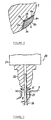
- FIG. 1 is a longitudinal section of a cylinder head of a four-cycle, five-valve engine
- Figure 2 is an expanded detailed view of portion A (valve seat portion on the intake side) in Figure 1.
- each gas cylinder is equipped with three intake valves 1-1 and 1-2 (1-1 designates the intake valves on both sides, and 1-2 designates the intake valve in the center (center valve)) and two exhaust valves 2.
- Three intake ports 4 and two exhaust ports 5, which are provided on a cylinder head 3 made of a lightweight cast aluminum alloy, are opened and closed by the aforementioned intake valves 1-1 and 1-2 and exhaust valves 2 with the proper timing, whereby the necessary gas exchange is achieved.
- JIS AC2B, AC4B, AC4C, or the like can be selected as the cast aluminum alloy, a material for the cylinder head 3.
- a concave combustion dome 3a constituting a combustion chamber 16 is formed on the bottom surface of the aforementioned cylinder head 3, and valve seats 6 and 7 designed to intermittently accommodate the aforementioned intake valves 1-1 and 1-2 and exhaust valves 2, respectively, are mounted along the rims of openings in the combustion chamber 16 of the aforementioned intake ports 4 and exhaust ports 5 formed in the cylinder head 3.
- the intake valves 1-1 and 1-2 and exhaust valves 2 are slidably passed through valve guides 8 and 9, respectively, and these are actuated in the direction of closure by valve springs 10 and 11.
- the intake valves 1-1 and 1-2 and the exhaust valves 2 are driven with the proper timing by rotating cams 14 and 15 that slide in valve lifters 12 and 13.
- valve seats 6 and 7 will now be described.
- valve seats 6 and 7 are joined-type valve seats which are shaped as rings from an iron-based sinter having excellent impact resistance, abrasion resistance, and high-temperature strength and which are metallurgically joined to the cylinder head 3 by the resistance heat joining technique pertaining to the present invention.
- the iron-based sinter of said valve seats 6 and 7 is filled with copper or another metal by infiltration in order to endow the valve seats 6 and 7 with high thermal conductivity, impact resistance, or the like.
- FIG. 2 Details of a joint of the intake-side valve seat 6 are shown here in Figure 2.
- a plastic deformation layer 25 described below is formed on the side of the cylinder head 3, with the joining interface between said valve seat 6 and cylinder head 3 serving as a boundary.
- Three tapered surfaces 6a, 6b and 6c are formed around the inside of this valve seat 6, with the tapered surface 6b serving as the work face (seat face) for the aforementioned intake valves 1-1 and 1-2.
- Two tapered surfaces 6d and 6e are formed around the outside of the valve seat 6, and the area where the two tapered surfaces 6d and 6e meet constitutes a blunt protruding portion 6f.
- the valve seat 7 on the exhaust side has the same cross-sectional shape as the valve seat 6 on the intake side, and any description thereof will therefore be omitted.
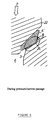
- Figure 3 is a schematic block diagram of a resistance welding apparatus
- Figures 4 through 9 are partial cross sections illustrating the process for joining a valve seat
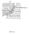
- Figure 10 is an expanded detailed drawing of portion B in Figure 6.
- the resistance welding apparatus 20 shown in Figure 3 comprises a pressure device 21, an electrode 22 pressed with said pressure device 21, and a power supply (not shown) designed to supply power to said electrode 22.
- the electrode 22 is made of copper or a copper alloy, a round hole 22a is bored in the center thereof, and a round guide bar 23 is slidably fitted inside said round hole 22a.
- a cylinder head 3 and a seat ring 6' are set in the resistance welding apparatus 20 having this structure in a manner such as that shown in the drawing. Specifically, the cylinder head 3 is positioned by fitting the aforementioned guide bar 23 of the resistance welding apparatus 20 into a valve guide hole 3b formed therein, ensuring that the rim of the opening in the intake port 4 formed in said cylinder head 3 is accurately positioned with respect to the electrode 22.
- the seat ring 6', as a workpiece for the valve seat 6, is shaped as a ring from an iron-based sinter. Details of the cross-sectional shape thereof are shown in Figure 4.
- said seat ring 6' is set in a manner such that the protruding portion 6a' of the outer periphery thereof comes into contact with the rim of the opening in the intake port 4 of the cylinder head 3 (as shown in Figure 4), the electrode 22 is then lowered along the guide bar 23 by the pressure device 21 (shown in Figure 3) and fitted against the tapered surface 6b' around the inside of the seat ring 6', and a process is started in which the seat ring 6' is pressed with a prescribed welding pressure P by the electrode 22.
- the cylinder head 3 which is made of a cast aluminum alloy with a lower deformation resistance than that of the iron-based sinter of the seat ring 6', undergoes plastic deformation as shown in Figure 5, and the seat ring 6' gradually penetrates into the cylinder head 3.
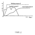
- Figures 11 and 12 show examples of patterns for supplying electric current to the electrode 22, welding pressure patterns, amounts of sinking of the seat ring (axial displacement of the electrode 22), and displacement velocities (rates at which the axial displacement of the electrode 22 changes over time).
- the electric current I is lowered temporarily and then restored to the same level, the welding pressure P is applied in two steps, and the sinking S of the seat ring 6' increases nonlinearly until it reaches the final value.
- the electric current I is supplied in steps (three steps) such that it gradually increases, the welding pressure P is applied such that the final value is instantaneously achieved, and the sinking S of the seat ring 6' increases nonlinearly until it reaches the final value.
- the temperature during the process for joining the cylinder head 3, which is made of a cast aluminum alloy (low-melting material), is prevented from exceeding the solidus temperature of the cast aluminum alloy and is kept within a temperature range in which the cast aluminum alloy can move as a plastic flow while remaining in the solid phase near the joining interface.
- the time during which the electric current is passed through the electrode 22 of the resistance welding apparatus 20 should be sufficient to allow the cast aluminum alloy to move as a plastic flow while remaining in the solid phase near the joining interface.
- the difference between the solidus temperatures of the dissimilar metals having different melting points is set to 340°C or higher.
- the melting point of a metal is commonly defined as the lower temperature limit at which the liquid phase develops.
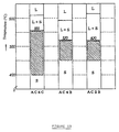
- Figure 13 shows the temperature ranges within which various types of cast aluminum alloys (AC4C, AC4B, and AC2B) can move as a plastic flow while remaining in the solid phase.
- “L” is the liquid phase
- “L + S” is a mixed solid/liquid phase
- “S” is the solid phase.
- the solidus temperatures for AC4C, AC4B, and AC2B are 555°C, 520°C, and 520°C, respectively.
- the temperature ranges within which a plastic flow can be maintained in the solid phase are 400 to 555°C for AC4C, and 450 to 520°C for AC4B and AC2B.
- the difference between the solidus temperature of this iron-based sinter and the solidus temperature of a cast aluminum alloy (low-melting material) is 340°C or greater.
- the temperature during the process for joining the seat ring 6' which is made of an iron-based sinter (high-melting material) is prevented from exceeding the phase transition temperature of said iron-based sinter.
- a TMA curve observed during the heating of the iron-based sinter is shown in Figure 14.
- the phase transition temperature of the iron-based sinter is 838.3°C, as shown in the drawing, and the temperature during the process for joining the seat ring 6' is kept at or below the phase transition temperature thereof (838.3°C).
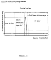
- FIG. 15 is a diagram depicting the concentration distribution of aluminum, which is the principal component of the cast aluminum alloy, near the joining interface between the seat ring 6' and the cylinder head 3.
- Metallurgical bonding is commonly defined as a process which, as opposed to mechanical bonding, prevents the joining interfaces from being displaced in relation to each other by the binding forces exerted by the interfaces on each other.
- Types of bonding can also be classified from the standpoint of the chemical bond theory into metallurgical bonding (bonding between atoms by means of free electrons acting as intermediaries), covalent bonding, ionic bonding, hydrogen bonding, and the like.
- metallurgical bonding bonding between atoms by means of free electrons acting as intermediaries
- covalent bonding ionic bonding
- hydrogen bonding hydrogen bonding
- There are also types of bonding that result from processes such as the mutual diffusion (solid-phase diffusion, liquid-phase diffusion) of atoms constituting metal materials.
- the method of the present invention primarily involves joining two metal materials by a combination of one or more of the types of bonding defined above with processes in which the atoms constituting dissimilar metal materials undergo solid-phase diffusion.
- the cast aluminum alloy constituting the cylinder head 3 forms a plastic flow in the direction of the arrows in Figure 10 at the joining interface with the seat ring 6', the oxide films covering the surfaces of the two metal materials is broken up by the aforementioned plastic flow of the cast aluminum alloy and pushed beyond the joining interface, and debris that has adhered to the joining surfaces of the two metal materials is also removed from the joining interface by the plastic flow of the cast aluminum alloy, with the result that the oxide film or debris is prevented from being entrained by the joining interface.
- controlling the pattern for supplying electric current to the electrode 22, the pattern for applying a welding pressure by the electrode 22, the displacement pattern of the electrode 22, and the like in such a manner makes it possible to complete the passage of electric current through the electrode 22 and to firmly join the seat ring 6' to the rim of the opening in the intake port 4 of the cylinder head 3 once the seat ring 6' has sunk into the cylinder head 3 to a prescribed extent, as shown in Figure 7.
- a plastic deformation layer 25 of prescribed thickness is formed on that side (aluminum alloy side) of the joining interface which faces the cylinder head 3.
- the joining method pertaining to the present invention involves metallurgically joining valve seats 6 and 7 to a cylinder head 3 by a resistance heat joining technique, and because the temperature during the process for joining the cast aluminum alloy that constitutes the cylinder head 3 is kept at or below the solidus temperature of the cast aluminum alloy, a molten reaction layer is prevented from forming at the joining interface between the two metal materials, and the valve seats 6 and 7 are firmly and metallurgically joined to the rims of the openings in the intake and exhaust ports 4 and 5 of the cylinder head 3 by the solid-phase diffusion of the iron and aluminum atoms constituting the two metal materials.
- the temperature during the process for joining the cast aluminum alloy should therefore be kept within the aforementioned temperature range (see Figure 13) close to the solidus temperature of said cast aluminum alloy in order to reduce the residual stress at the plastic deformation layer 25, to activate the joining flow of the cast aluminum alloy, to actively remove oxide films or debris from the joining interface, and to obtain high joining strength.
- the joining method pertaining to the present invention involves keeping the temperature during the process for joining the cast aluminum alloy (low-melting material) within a temperature range in which said cast aluminum alloy can move as a plastic flow while remaining in the solid phase near the joining interface, the oxide film that has formed on the joining surface of the two metal materials or the debris that has adhered to the joining surface is broken up by the plastic flow near the joining interface of the aluminum alloy material and are removed from the joining interface, preventing the oxide film or debris from being entrained by the joining interface, creating a sound joining interface as a result of direct contact between the two metal materials, and making it possible to firmly join the valve seats 6 and 7 to the cylinder head 3.
- Another feature of the method of the present invention is that the temperature during the process for joining an iron sinter, which is the high-melting material that constitutes the valve seats 6 and 7, is kept at or below the phase transition temperature of said iron sinter, with the result that the pronounced hardening caused by the phase transition (martensite transition) of said iron sinter is prevented, sufficient toughness is ensured for the valve seats 6 and 7, and the high impact resistance and other functions required for this material are not impaired.
- Yet another feature of the method of the present invention is that the extent to which the valve seats 6 and 7 sink into the cylinder head 3 can be set to a level required by design considerations.
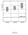
- Figure 16 shows the results obtained by measuring the joining strength of valve seats joined to cylinder heads by the method of the present invention. Specifically, Figure 16 shows the results obtained by selecting AC4C, AC4B, and AC2B as the materials for the cylinder heads, and measuring the load (peel load) needed to peel off the valve seats joined to the cylinder heads made of these materials. The peel load exceeded the allowable level in all cases, and the joining strength of each valve seat was sufficient to withstand actual use.
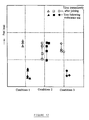
- Figure 17 shows the results obtained by measuring the joining strength (peel load) of valve seats immediately after they had been joined under various joining and heating conditions (conditions 1, 2, and 3), as well as the joining strength (endurance strength) achieved after a temperature of 300°C had been maintained for 24 hours.
- the joining strength (peel load) of the valve seats dropped following endurance tests under conditions 1 and 3, but under condition 2 the joining strength (peel load) of the valve seats did not decrease even after endurance tests had been conducted, and remained about the same as the joining strength (peel load) observed immediately after joining.
- the present invention was described above with reference to a particular case of a method for joining valve seats to cylinder heads in an internal combustion engine, it is apparent that the present invention is applicable to cases in which a seat composed of an SKD material or other material with high abrasion resistance is joined to the top face of a valve lifter composed of a lightweight aluminum alloy, magnesium alloy, or the like; and to other cases in which any dissimilar metal materials having different melting points are joined.
- a merit of the present invention is that it is possible to prevent a molten reaction layer from forming at the joining interface between two metal materials, to firmly and metallurgically join the two metal materials by the solid-phase diffusion of the metal atoms that constitute the two metal materials, and to join the dissimilar metal materials with sufficient strength because the temperature during the process for joining the low-melting material is prevented from exceeding the solidus temperature of said low-melting material in a method for joining dissimilar metal materials having different melting points by a resistance heat joining technique, that is, in a method for metallurgically joining two dissimilar metal materials by forming a plastic deformation layer at least on the low-melting material side of the joining interface.
Landscapes
- Engineering & Computer Science (AREA)
- Mechanical Engineering (AREA)
- General Engineering & Computer Science (AREA)
- Chemical & Material Sciences (AREA)
- Combustion & Propulsion (AREA)
- Cylinder Crankcases Of Internal Combustion Engines (AREA)
- Lift Valve (AREA)
- Pressure Welding/Diffusion-Bonding (AREA)
Applications Claiming Priority (2)
| Application Number | Priority Date | Filing Date | Title |
|---|---|---|---|
| JP47657/96 | 1996-03-05 | ||
| JP04765796A JP3546261B2 (ja) | 1996-03-05 | 1996-03-05 | 異種金属材料の接合方法 |
Publications (1)
| Publication Number | Publication Date |
|---|---|
| EP0794030A1 true EP0794030A1 (de) | 1997-09-10 |
Family
ID=12781337
Family Applications (1)
| Application Number | Title | Priority Date | Filing Date |
|---|---|---|---|
| EP97103662A Withdrawn EP0794030A1 (de) | 1996-03-05 | 1997-03-05 | Verfahren zum Verbinden von Metalle und Ventilsitz eingesetzt in einem Zylinderkopf |
Country Status (3)
| Country | Link |
|---|---|
| US (1) | US5860401A (de) |
| EP (1) | EP0794030A1 (de) |
| JP (1) | JP3546261B2 (de) |
Cited By (1)
| Publication number | Priority date | Publication date | Assignee | Title |
|---|---|---|---|---|
| EP0940214B1 (de) * | 1998-02-18 | 2006-04-26 | William Prym GmbH & Co. KG | Verfahren zum Verbinden von zwei aus härtemässig zueinander unterschiedlichen Metallen bestehenden Teilen mittels Laserlicht |
Families Citing this family (15)
| Publication number | Priority date | Publication date | Assignee | Title |
|---|---|---|---|---|
| DE19540398C1 (de) * | 1995-10-30 | 1997-03-27 | Daimler Benz Ag | Zylinderkopf für Brennkraftmaschinen |
| WO1999019271A1 (de) * | 1997-10-13 | 1999-04-22 | Ceramtec Ag Innovative Ceramic Engineering | Verfahren zur erhöhung der verschleissbeständigkeit eines werkstückes |
| SE517687C2 (sv) * | 1997-12-23 | 2002-07-02 | Scania Cv Ab | Cylinderhuvud för förbränningsmotorer |
| DE60010813T2 (de) * | 1999-08-06 | 2004-10-07 | Honda Motor Co Ltd | Diffusionsverbindungsverfahren |
| JP4178758B2 (ja) * | 2001-02-08 | 2008-11-12 | 株式会社豊田自動織機 | バルブシートの接合構造 |
| DE102007031464A1 (de) * | 2006-07-17 | 2008-01-24 | Alstom Technology Ltd. | Dampfeinlassventil einer Dampfturbine |
| NL2001869C2 (nl) * | 2008-08-01 | 2010-02-02 | Stichting Materials Innovation | Cilinderkop met klepzitting alsmede werkwijze voor het vervaardigen daarvan. |
| US8662045B2 (en) * | 2009-08-03 | 2014-03-04 | GM Global Technology Operations LLC | Cylinder head assembly for an internal combustion engine |
| CN103260809B (zh) * | 2010-12-14 | 2016-01-06 | 日产自动车株式会社 | 导电材料的接合体 |
| JP5897712B2 (ja) * | 2012-11-22 | 2016-03-30 | 株式会社エフ・シー・シー | 一体部材の製造方法及び一体部材 |
| JP5990343B2 (ja) * | 2014-08-18 | 2016-09-14 | オリジン電気株式会社 | 金属接合体及び金属接合体の製造方法 |
| JP7066551B2 (ja) * | 2018-06-29 | 2022-05-13 | 本田技研工業株式会社 | 接合装置及び接合方法 |
| JP7374836B2 (ja) * | 2020-03-31 | 2023-11-07 | 本田技研工業株式会社 | 金属部材の接合方法 |
| DE112022000120T5 (de) * | 2021-04-30 | 2023-06-29 | Mitsubishi Heavy Industries, Ltd. | Dampfventil |
| CN116164151B (zh) * | 2023-04-21 | 2023-07-18 | 东方电气集团东方电机有限公司 | 球阀安装结构以及水力发电系统 |
Citations (7)
| Publication number | Priority date | Publication date | Assignee | Title |
|---|---|---|---|---|
| GB1150005A (en) * | 1965-08-09 | 1969-04-30 | North American Aviation Inc | Method of joining aluminium and ferrous members |
| US3766633A (en) * | 1970-12-10 | 1973-10-23 | Kernforschungsanlage Juelich | Method of joining metals of different melting points |
| EP0092081A1 (de) * | 1982-04-21 | 1983-10-26 | Nissan Motor Co., Ltd. | Leichtmetallzylinderkopf mit Ventilsitzeinsatz |
| US4831976A (en) * | 1987-02-02 | 1989-05-23 | General Motors Corporation | Engine with valve seat inserts and method of retaining |
| US4896638A (en) * | 1988-12-07 | 1990-01-30 | Ford Motor Company | Fabricating internal combustion engine cylinder heads with close tolerance internal surfaces |
| DE4409451A1 (de) * | 1994-03-18 | 1995-09-21 | Manfred Wanzke | Verfahren zum Verbinden unterschiedlicher metallischer Werkstoffe |
| EP0743428A1 (de) * | 1995-05-15 | 1996-11-20 | Yamaha Hatsudoki Kabushiki Kaisha | Ventilsitzeinsatz |
Family Cites Families (3)
| Publication number | Priority date | Publication date | Assignee | Title |
|---|---|---|---|---|
| JPS62150014A (ja) * | 1985-12-25 | 1987-07-04 | Toyota Motor Corp | アルミニウム合金製バルブシ−トレスシリンダヘツド |
| US4791259A (en) * | 1987-01-28 | 1988-12-13 | Tocco, Inc. | Method and apparatus for retaining a valve seat insert |
| JP3287916B2 (ja) * | 1993-07-20 | 2002-06-04 | ヤマハ発動機株式会社 | バルブシートの接合構造 |
-
1996
- 1996-03-05 JP JP04765796A patent/JP3546261B2/ja not_active Expired - Fee Related
-
1997
- 1997-02-25 US US08/804,456 patent/US5860401A/en not_active Expired - Fee Related
- 1997-03-05 EP EP97103662A patent/EP0794030A1/de not_active Withdrawn
Patent Citations (7)
| Publication number | Priority date | Publication date | Assignee | Title |
|---|---|---|---|---|
| GB1150005A (en) * | 1965-08-09 | 1969-04-30 | North American Aviation Inc | Method of joining aluminium and ferrous members |
| US3766633A (en) * | 1970-12-10 | 1973-10-23 | Kernforschungsanlage Juelich | Method of joining metals of different melting points |
| EP0092081A1 (de) * | 1982-04-21 | 1983-10-26 | Nissan Motor Co., Ltd. | Leichtmetallzylinderkopf mit Ventilsitzeinsatz |
| US4831976A (en) * | 1987-02-02 | 1989-05-23 | General Motors Corporation | Engine with valve seat inserts and method of retaining |
| US4896638A (en) * | 1988-12-07 | 1990-01-30 | Ford Motor Company | Fabricating internal combustion engine cylinder heads with close tolerance internal surfaces |
| DE4409451A1 (de) * | 1994-03-18 | 1995-09-21 | Manfred Wanzke | Verfahren zum Verbinden unterschiedlicher metallischer Werkstoffe |
| EP0743428A1 (de) * | 1995-05-15 | 1996-11-20 | Yamaha Hatsudoki Kabushiki Kaisha | Ventilsitzeinsatz |
Cited By (1)
| Publication number | Priority date | Publication date | Assignee | Title |
|---|---|---|---|---|
| EP0940214B1 (de) * | 1998-02-18 | 2006-04-26 | William Prym GmbH & Co. KG | Verfahren zum Verbinden von zwei aus härtemässig zueinander unterschiedlichen Metallen bestehenden Teilen mittels Laserlicht |
Also Published As
| Publication number | Publication date |
|---|---|
| JP3546261B2 (ja) | 2004-07-21 |
| JPH09239566A (ja) | 1997-09-16 |
| US5860401A (en) | 1999-01-19 |
Similar Documents
| Publication | Publication Date | Title |
|---|---|---|
| EP0794030A1 (de) | Verfahren zum Verbinden von Metalle und Ventilsitz eingesetzt in einem Zylinderkopf | |
| US5787853A (en) | Valve seat-bonding area structures and valve seat-bonded cylinder head with the structures | |
| US5802716A (en) | Method for bonding a valve seat with a cylinder head | |
| EP0723069B1 (de) | Ventil-Sitz für einen Zylinderkopf und Verfahren zu ihrer Herstellung | |
| JPH0734965A (ja) | バルブシートの接合構造 | |
| WO1993011896A1 (en) | Metallurgically bonding inserts in a casting | |
| US20080237304A1 (en) | Engine component having friction welded inserts | |
| JPH08246821A (ja) | バルブシート | |
| EP0743428A1 (de) | Ventilsitzeinsatz | |
| US5768779A (en) | Method of manufacturing cylinder head for engine | |
| EP0751284A1 (de) | Zylinderkopf und Verfahren zur Herstellung eines Ventilsitzes | |
| JP5015393B2 (ja) | シート肉盛を施されたエンジンバルブおよびその製作方法 | |
| US5687685A (en) | Valve seat and method | |
| US2403926A (en) | Sheathed valve | |
| US2064155A (en) | Valve and seat for internal combustion engines | |
| US5778531A (en) | Method of manufacturing cylinder head for engine | |
| US5809968A (en) | Cylinder head and flow passage therefor | |
| US20040182332A1 (en) | Liquid-cooled valve seat ring | |
| EP0819836B1 (de) | Zylinderkopf und Verfahren zur Herstellung eines Ventilsitzes | |
| US5761806A (en) | Method of bonding valve seat | |
| KR102786254B1 (ko) | 가스 교환 밸브의 밸브 시트 링 및 가스 교환 밸브 | |
| CN113798419B (zh) | 制造活塞的方法 | |
| US20080236536A1 (en) | Cast engine component having metallurgically bonded inserts | |
| JP2000240504A (ja) | バルブシート付きシリンダヘッド | |
| JP3416829B2 (ja) | シリンダヘッドおよびその製造方法 |
Legal Events
| Date | Code | Title | Description |
|---|---|---|---|
| PUAI | Public reference made under article 153(3) epc to a published international application that has entered the european phase |
Free format text: ORIGINAL CODE: 0009012 |
|
| AK | Designated contracting states |
Kind code of ref document: A1 Designated state(s): DE FR GB IT |
|
| 17P | Request for examination filed |
Effective date: 19980304 |
|
| 17Q | First examination report despatched |
Effective date: 19990913 |
|
| STAA | Information on the status of an ep patent application or granted ep patent |
Free format text: STATUS: THE APPLICATION IS DEEMED TO BE WITHDRAWN |
|
| 18D | Application deemed to be withdrawn |
Effective date: 20020924 |