EP0794064B1 - Appareil de détection de fin de papier - Google Patents
Appareil de détection de fin de papier Download PDFInfo
- Publication number
- EP0794064B1 EP0794064B1 EP97103751A EP97103751A EP0794064B1 EP 0794064 B1 EP0794064 B1 EP 0794064B1 EP 97103751 A EP97103751 A EP 97103751A EP 97103751 A EP97103751 A EP 97103751A EP 0794064 B1 EP0794064 B1 EP 0794064B1
- Authority
- EP
- European Patent Office
- Prior art keywords
- paper
- detecting
- paper roll
- protruding portion
- piece
- Prior art date
- Legal status (The legal status is an assumption and is not a legal conclusion. Google has not performed a legal analysis and makes no representation as to the accuracy of the status listed.)
- Expired - Lifetime
Links
- 238000007639 printing Methods 0.000 claims description 9
- 238000001514 detection method Methods 0.000 description 5
- 239000011347 resin Substances 0.000 description 4
- 229920005989 resin Polymers 0.000 description 4
- XECAHXYUAAWDEL-UHFFFAOYSA-N acrylonitrile butadiene styrene Chemical compound C=CC=C.C=CC#N.C=CC1=CC=CC=C1 XECAHXYUAAWDEL-UHFFFAOYSA-N 0.000 description 2
- 229920000122 acrylonitrile butadiene styrene Polymers 0.000 description 2
- 239000004676 acrylonitrile butadiene styrene Substances 0.000 description 2
- 238000010276 construction Methods 0.000 description 2
- 229920006324 polyoxymethylene Polymers 0.000 description 2
- 229930182556 Polyacetal Natural products 0.000 description 1
- 230000001419 dependent effect Effects 0.000 description 1
- 238000010586 diagram Methods 0.000 description 1
- 238000001810 electrochemical catalytic reforming Methods 0.000 description 1
- -1 for example Polymers 0.000 description 1
- 239000002184 metal Substances 0.000 description 1
- 230000003287 optical effect Effects 0.000 description 1
- 238000007651 thermal printing Methods 0.000 description 1
Images


Classifications
-
- B—PERFORMING OPERATIONS; TRANSPORTING
- B41—PRINTING; LINING MACHINES; TYPEWRITERS; STAMPS
- B41J—TYPEWRITERS; SELECTIVE PRINTING MECHANISMS, i.e. MECHANISMS PRINTING OTHERWISE THAN FROM A FORME; CORRECTION OF TYPOGRAPHICAL ERRORS
- B41J11/00—Devices or arrangements of selective printing mechanisms, e.g. ink-jet printers or thermal printers, for supporting or handling copy material in sheet or web form
- B41J11/66—Applications of cutting devices
- B41J11/70—Applications of cutting devices cutting perpendicular to the direction of paper feed
-
- B—PERFORMING OPERATIONS; TRANSPORTING
- B26—HAND CUTTING TOOLS; CUTTING; SEVERING
- B26D—CUTTING; DETAILS COMMON TO MACHINES FOR PERFORATING, PUNCHING, CUTTING-OUT, STAMPING-OUT OR SEVERING
- B26D1/00—Cutting through work characterised by the nature or movement of the cutting member or particular materials not otherwise provided for; Apparatus or machines therefor; Cutting members therefor
- B26D1/01—Cutting through work characterised by the nature or movement of the cutting member or particular materials not otherwise provided for; Apparatus or machines therefor; Cutting members therefor involving a cutting member which does not travel with the work
- B26D1/12—Cutting through work characterised by the nature or movement of the cutting member or particular materials not otherwise provided for; Apparatus or machines therefor; Cutting members therefor involving a cutting member which does not travel with the work having a cutting member moving about an axis
- B26D1/25—Cutting through work characterised by the nature or movement of the cutting member or particular materials not otherwise provided for; Apparatus or machines therefor; Cutting members therefor involving a cutting member which does not travel with the work having a cutting member moving about an axis with a non-circular cutting member
- B26D1/26—Cutting through work characterised by the nature or movement of the cutting member or particular materials not otherwise provided for; Apparatus or machines therefor; Cutting members therefor involving a cutting member which does not travel with the work having a cutting member moving about an axis with a non-circular cutting member moving about an axis substantially perpendicular to the line of cut
- B26D1/30—Cutting through work characterised by the nature or movement of the cutting member or particular materials not otherwise provided for; Apparatus or machines therefor; Cutting members therefor involving a cutting member which does not travel with the work having a cutting member moving about an axis with a non-circular cutting member moving about an axis substantially perpendicular to the line of cut with limited pivotal movement to effect cut
- B26D1/305—Cutting through work characterised by the nature or movement of the cutting member or particular materials not otherwise provided for; Apparatus or machines therefor; Cutting members therefor involving a cutting member which does not travel with the work having a cutting member moving about an axis with a non-circular cutting member moving about an axis substantially perpendicular to the line of cut with limited pivotal movement to effect cut for thin material, e.g. for sheets, strips or the like
-
- B—PERFORMING OPERATIONS; TRANSPORTING
- B26—HAND CUTTING TOOLS; CUTTING; SEVERING
- B26D—CUTTING; DETAILS COMMON TO MACHINES FOR PERFORATING, PUNCHING, CUTTING-OUT, STAMPING-OUT OR SEVERING
- B26D7/00—Details of apparatus for cutting, cutting-out, stamping-out, punching, perforating, or severing by means other than cutting
- B26D7/22—Safety devices specially adapted for cutting machines
- B26D7/24—Safety devices specially adapted for cutting machines arranged to disable the operating means for the cutting member
-
- B—PERFORMING OPERATIONS; TRANSPORTING
- B41—PRINTING; LINING MACHINES; TYPEWRITERS; STAMPS
- B41J—TYPEWRITERS; SELECTIVE PRINTING MECHANISMS, i.e. MECHANISMS PRINTING OTHERWISE THAN FROM A FORME; CORRECTION OF TYPOGRAPHICAL ERRORS
- B41J11/00—Devices or arrangements of selective printing mechanisms, e.g. ink-jet printers or thermal printers, for supporting or handling copy material in sheet or web form
- B41J11/0075—Low-paper indication, i.e. indicating the state when copy material has been used up nearly or completely
-
- B—PERFORMING OPERATIONS; TRANSPORTING
- B41—PRINTING; LINING MACHINES; TYPEWRITERS; STAMPS
- B41J—TYPEWRITERS; SELECTIVE PRINTING MECHANISMS, i.e. MECHANISMS PRINTING OTHERWISE THAN FROM A FORME; CORRECTION OF TYPOGRAPHICAL ERRORS
- B41J11/00—Devices or arrangements of selective printing mechanisms, e.g. ink-jet printers or thermal printers, for supporting or handling copy material in sheet or web form
- B41J11/02—Platens
- B41J11/04—Roller platens
-
- B—PERFORMING OPERATIONS; TRANSPORTING
- B41—PRINTING; LINING MACHINES; TYPEWRITERS; STAMPS
- B41J—TYPEWRITERS; SELECTIVE PRINTING MECHANISMS, i.e. MECHANISMS PRINTING OTHERWISE THAN FROM A FORME; CORRECTION OF TYPOGRAPHICAL ERRORS
- B41J15/00—Devices or arrangements of selective printing mechanisms, e.g. ink-jet printers or thermal printers, specially adapted for supporting or handling copy material in continuous form, e.g. webs
- B41J15/04—Supporting, feeding, or guiding devices; Mountings for web rolls or spindles
- B41J15/042—Supporting, feeding, or guiding devices; Mountings for web rolls or spindles for loading rolled-up continuous copy material into printers, e.g. for replacing a used-up paper roll; Point-of-sale printers with openable casings allowing access to the rolled-up continuous copy material
-
- B—PERFORMING OPERATIONS; TRANSPORTING
- B41—PRINTING; LINING MACHINES; TYPEWRITERS; STAMPS
- B41J—TYPEWRITERS; SELECTIVE PRINTING MECHANISMS, i.e. MECHANISMS PRINTING OTHERWISE THAN FROM A FORME; CORRECTION OF TYPOGRAPHICAL ERRORS
- B41J2/00—Typewriters or selective printing mechanisms characterised by the printing or marking process for which they are designed
- B41J2/315—Typewriters or selective printing mechanisms characterised by the printing or marking process for which they are designed characterised by selective application of heat to a heat sensitive printing or impression-transfer material
- B41J2/32—Typewriters or selective printing mechanisms characterised by the printing or marking process for which they are designed characterised by selective application of heat to a heat sensitive printing or impression-transfer material using thermal heads
-
- B—PERFORMING OPERATIONS; TRANSPORTING
- B41—PRINTING; LINING MACHINES; TYPEWRITERS; STAMPS
- B41J—TYPEWRITERS; SELECTIVE PRINTING MECHANISMS, i.e. MECHANISMS PRINTING OTHERWISE THAN FROM A FORME; CORRECTION OF TYPOGRAPHICAL ERRORS
- B41J29/00—Details of, or accessories for, typewriters or selective printing mechanisms not otherwise provided for
- B41J29/02—Framework
-
- B—PERFORMING OPERATIONS; TRANSPORTING
- B41—PRINTING; LINING MACHINES; TYPEWRITERS; STAMPS
- B41J—TYPEWRITERS; SELECTIVE PRINTING MECHANISMS, i.e. MECHANISMS PRINTING OTHERWISE THAN FROM A FORME; CORRECTION OF TYPOGRAPHICAL ERRORS
- B41J29/00—Details of, or accessories for, typewriters or selective printing mechanisms not otherwise provided for
- B41J29/46—Applications of alarms, e.g. responsive to approach of end of line
- B41J29/48—Applications of alarms, e.g. responsive to approach of end of line responsive to breakage or exhaustion of paper or approach of bottom of paper
Definitions
- the present invention relates to a paper termination detecting apparatus.
- This type of paper termination detecting apparatus is disclosed in, for example, Japanese Utility Model Laid-Open Publication Nos. Sho. 61-3872 and Hei. 1-14597.
- a detecting piece constantly urges the side of a roll of print paper. When an amount of the paper roll remaining to be used for printing is reduced to below a predetermined amount of paper, the detecting piece is put in a space of the core part of the paper roll. According to that operation, a detecting switch operates and recognizes the amount of the residual paper roll being small.
- the conventional apparatus suffer from the following disadvantage.
- the paper roll is swung or moved toward the printer where paper feeding means is provided, and therefore, the paper roll is frequently located out of a desired detecting position where the detecting piece is placed.
- a detecting lever having the detecting piece is out of the side of the paper roll.
- the detecting lever is turned as in case where the detecting piece is put into the core space of the paper roll.
- the detecting switch operates.
- the paper termination detecting apparatus mistakenly operates, to produce an incorrect amount of the residual print paper. The result allows the wasteful use of the paper.
- the present invention intends to overcome the above problems.
- the object is solved by the paper termination detecting apparatus according to independent claim 1 and by the printing apparatus according to independent claim 6.
- the present invention generally relates to a paper termination detecting apparatus.
- a paper termination detecting apparatus In particular it relates to an apparatus for detecting a near end of a paper roll to be supplied to a printer.
- an object of the present invention is to provide a reliable, paper termination detecting apparatus which can accurately detect the termination of a paper roll.
- a paper termination detecting apparatus for detecting an amount of a paper roll that is below a predetermined amount of paper, according to claim 1.
- a top of the detecting piece (first protruding portion) of the detecting lever is substantially flush with a top of the protruding piece thereof on the side of the paper roll.
- the detecting lever includes a detecting piece and a protruded piece spaced a predetermined distance apart from the detecting piece.
- the top of the detecting piece of the detecting lever is substantially flush with the top of the protruded piece thereof on the side of the paper roll. Therefore, when the detecting piece moves out of the side of the paper roll but the protruded piece comes in contact with the roll side, the detecting lever is little turned.
- a paper termination detecting apparatus for detecting an amount of a paper roll that is below a predetermined amount of paper, according to claim 1.
- Fig. 1 is a perspective view showing a printer incorporating the present invention thereinto in a state that a cover frame is opened.
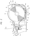
- Fig. 2 is a longitudinal sectional view showing of the printer when the cover frame is closed.
- Fig. 3 is a front view showing the paper termination detecting apparatus according to the present invention.
- Fig. 4 is a side view showing the paper termination detecting apparatus according to the present invention.
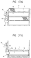
- Figs. 5(a) and 5(b) are views showing an operation of the paper termination detecting apparatus of the present embodiment: Fig. 5(a) is a sectional view showing an off-state of the paper termination detecting apparatus; and Fig. 5(b) is a sectional view showing an on-state of the paper termination detecting apparatus.
- Fig. 1 is a perspective view showing a printer incorporating the present invention thereinto in a state that a cover frame 10 is opened.
- the printer is a receipt printer of the type which is used for a POS system, for example. Characters, for example, are recorded or printed on a rolled recording or print paper S as one form of a recording medium, by a line thermal printing head 39 (Fig. 2).
- a printing unit and a paper cutting unit are disposed in the fore section, while a paper roll container for containing a paper roll S is disposed in the rear section.
- the printer includes the cover frame 10 and an auto cutter unit 11 for containing a movable blade 32 and a drive means for driving the blade.
- the cover frame 10 is provided above the paper roll container in a state that it may be turned up for opening and turned down for closing.
- the cover frame 10 may be turned about support shafts 14, which are provided at the upper ends of both sides of a main frame 13 made of metal, for example.
- the cover frame 10 is turned up for opening and turned down for closing.
- the cover frame 10 has an arcuate cover portion 15, a platen 18 and a fixed blade 33.
- the arcuate cover portion 15 is curved upward such that when the cover frame 10 is closed, it can receive the print paper S in a noncontact fashion.
- a paper roll holder 17 made of resin is disposed within the main frame. It is seen when the cover frame 10 is opened.
- a paper termination detecting apparatus 24 is mounted on the left side of the main frame 13. The apparatus 24 is provided for detecting an amount of paper roll S remaining in the paper roll container.
- Fig. 2 is a longitudinal sectional view showing of the printer when the cover frame is closed, a print paper S is set in the paper roll holder 17, and the paper is being fed to the printer.
- the diameter of the print paper S is still large since the paper roll is in the initial stage of use.
- the paper termination detecting apparatus 24 detects the reduced diameter of the paper roll.
- the print paper S rolled out of the paper roll is nipped between the platen 18 and the thermal print head 39, and when the platen 18 is turned, it is fed forward by a frictional force acting between the paper and the platen 18. After passing the thermal print head 39, the paper S passes between the movable blade 32 and the fixed blade 33 in the direction of an arrow D. When the paper S reaches a preset position, the movable blade 32 is driven to move to the movable blade 32 to cut the paper S.
- Figs. 3 and 4 are front and side views showing the paper termination detecting apparatus 24 according to the present invention.
- the paper termination detecting apparatus 24 is generally constructed with a detecting frame 62 and a detecting lever 63, both being long members.
- the frames 62 and 63 are both made of resin, for example, acrylonitrile-butadiene-styrene copolymer (ABS) or polyacetal (POM).
- Support shafts 63a and 63b are provided at the base end of the detecting lever 63 while being disposed symmetrically with respect to the lever.
- the detecting lever 63 is mounted on the detecting frame 62 in such a fashion that the lever 63 may be turned about those support shafts 63a and 63b.
- the detecting piece 64 to be in contact with the side of the print paper S is formed at the end of the detecting lever 63.
- the detecting piece 64 made of, for example, resin may be integral with the detecting lever 63.
- the detecting piece 64 extends at a right angle to the longitudinal direction of the detecting lever 63.
- the detecting piece 64 is narrowed toward its top so that it easily enters a space 76 of a core part 75 of the paper roll, as will be described in detail later.
- a protruding piece 65 to be described later is provided at the middle of the detecting lever 63.
- the protruded piece 65 is constructed with a plate-like member made of resin, for example.
- the protruded piece 65 similar to the detecting piece 64, extends at a right angle to the longitudinal direction of the detecting lever 63.
- the protruding piece 65 is slightly shorter than the detecting piece 64.
- the protruding piece 65 may be integral with the detecting lever 63.
- the protruding piece 65 includes a face 65a, which is slanted down from the top of the protruded piece toward the detecting piece 64 side. Accordingly, when the protruding piece 65 is viewed from its side, the protruded piece 65 is narrowed toward its top.
- a window 62a is formed in the detecting frame 62.
- the window 62a allows the protruding piece 65 of the detecting lever 63 to escape therethrough.
- a limit switch 67 is provided on a support 66, which extends outward from the middle of the detecting frame 62.
- the detecting switch 67 is turned on and off with the turn of the detecting lever 63.
- a spring contained in the detecting switch 67 urges a switch pin 68 to press the detecting lever 63 against the detecting frame 62.
- the detecting switch 67 is connected to a main circuit board (not shown) which controls the printer by an FFC, for example.
- Figs. 5(a) and 5(b) are diagrams showing an operation of the paper termination detecting apparatus 24 of the present embodiment.
- Fig. 5(a) is a sectional view showing an off-state of the paper termination detecting apparatus 24.
- Fig. 5(b) is a sectional view showing an on-state of the paper termination detecting apparatus 24.
- the detecting piece 64 or the protruded piece 65 of the detecting lever 63 is abutted against the side of a roll of the print paper S, as shown in Fig. 5(a). Accordingly, the detecting lever 63 is pushed back, so that the detecting switch 67 retains an off state.
- the transportation of the print paper S is not interruptive (in the serial printer, the print paper S is transported in an interruptive manner). Therefore, when the print paper S, which has been loosened by a pulling-up motion of the paper roll, is horizontally or widthwise shifted with respect to the paper roll, it is impossible to correct such a horizontal shift.
- the paper roll holder 17 includes a gently slanted support surface 17c, (Fig. 2) which extends over an area of the paper feeding side of the guide 38, whereby the paper roll is allowed to horizontally shift in some degree by the pulling-up motion.
- a gently slanted support surface 17c (Fig. 2) which extends over an area of the paper feeding side of the guide 38, whereby the paper roll is allowed to horizontally shift in some degree by the pulling-up motion.
- the detecting piece 64 of the detecting lever 63 is out of the side of the paper roll.
- the detecting lever 63 is not turned, and the detecting switch 67 is left off.
- the protruding piece 65 which faces the print paper S, is included in the detecting lever 63. With provision of the protruding piece 65, if the print paper S is horizontally shifted, the paper termination detecting apparatus 24 retains an off state. Therefore, an exact detection of the termination of the print paper is ensured.
- the present invention is not limited to the case of continuously feeding the paper and the shape of the paper roll container, but may be applicable to other suitable cases.
- the serial printer such as a dot impact printer where the paper is intermittently fed for short time
- the paper is instantly moved forward without being continuously pulled up.
- the detecting lever 63 remains immovable so long as the protruded piece 65 is in contact with the side of the paper roll. Therefore, an exact detection of the paper termination is secured.
- the protruded piece 65 is slightly shorter than the detecting piece 64.
- the top 64a of the detecting piece 64 of the detecting lever 63 is substantially flush with the top 65b of the protruding piece 65 thereof on the side of the paper roll. Therefore, when the detecting piece 64 is out of the side of the paper roll but the protruding piece 65 is in contact with the roll side, the detecting lever 63 is little turned, thereby improving a detection accuracy.
- the slanted face 65a is formed on the lower portion of each of the detecting piece 64 and the protruded piece 65. Provision of the slanted face 65a brings about the following advantage.
- the detecting piece 64 can be put out of the space 76 of the core part 75 by merely lifting the core part 75 of the paper roll having the detecting piece 64 of the detecting lever 63 being put in the space 76 of the core part. Therefore, it is easy to remove the core part 75 from the paper roll container.
- a slanted face which is formed on the underside of the protruding piece 65, brings about the following advantage.
- the protruding piece 65 is smoothly moved outside with the aid of the slanted face thereof.
- the provision of the slanted faces of the detecting piece 64 and the protruding piece 65 provide an easy handling.
- the related distance and dimensions thereof are selected so as to be suitable for detection of two types of core parts of the paper rolls used for ECRs, desk top calculators, or the like: the first type core part having 18 mm in outside diameter and 12 mm in inside diameter, and the second type core part having 22 mm in outside diameter and 12 mm in inside diameter.
- the present invention may be applied to other special types of core part.
- limit switch is used for the paper termination detecting means in the embodiment mentioned above, any other suitable means, e.g., an optical switch, may be used instead.
- any other suitable means e.g., an optical switch
- use of the limit switch is advantageous in that the paper termination detection is simple and reliable.
- the paper termination detecting apparatus of the invention operates to detect an amount of paper roll remaining in the paper roll container only when it is reduced to a preset amount of paper. In this respect, a reliability of the apparatus is improved.
- the paper termination detecting apparatus can accurately detect the amount of residual paper roll.
Landscapes
- Life Sciences & Earth Sciences (AREA)
- Forests & Forestry (AREA)
- Engineering & Computer Science (AREA)
- Mechanical Engineering (AREA)
- Handling Of Continuous Sheets Of Paper (AREA)
- Controlling Sheets Or Webs (AREA)
- Controlling Rewinding, Feeding, Winding, Or Abnormalities Of Webs (AREA)
- Accessory Devices And Overall Control Thereof (AREA)
- Handling Of Sheets (AREA)
- Unwinding Webs (AREA)
Claims (10)
- Appareil de détection de fin de papier destiné à détecter une quantité prédéterminée de papier, comprenant :un levier de détection (63) possédant une première partie en saillie (64) destinée à être insérée dans un espace d'une partie de noyau d'un rouleau de papier, et une seconde partie en saillie (65) placée à une distance prédéterminée de la première partie en saillie (64) et mobile vers un espace qui se trouve au-dessus d'une surface cylindrique externe du rouleau de papier, etun interrupteur de détection (67) destiné à transformer un mouvement de levier de détection (63) en un signal électrique lorsque la première partie en saillie (64) pénètre dans l'espace de la partie de noyau du rouleau de papier et la seconde partie en saillie (65) se déplace vers l'espace formé au-dessus de la surface cylindrique externe du rouleau de papier.
- Appareil de détection de fin de papier selon la revendication 1, dans lequel la seconde partie en saillie (65) est au contact du côté du rouleau de papier, une partie supérieure (64a) de la première partie en saillie (64) du levier de détection (63) est pratiquement au niveau d'une partie supérieure (65b) de la seconde partie en saillie (65) de ce levier du côté du rouleau de papier.
- Appareil de détection de fin de papier selon la revendication 2, dans lequel chacune des seconde (65) et première (64) parties en saillie a une face inclinée.
- Appareil de détection de fin de papier selon l'une quelconque des revendications précédentes, dans lequel l'interrupteur de détection (67) est un interrupteur de limite.
- Appareil de détection de fin de papier selon la revendication 4, dans lequel le levier de détection (63) est destiné à pivoter et est raccordé à l'interrupteur de limite (67).
- Appareil d'impression, comprenant :un support (17) de rouleau de papier destiné à loger du papier en rouleau,un levier de détection (63) possédant une première partie en saillie (64) destinée à être insérée dans un espace d'une partie de noyau du rouleau de papier, et une seconde partie en saillie (65) placée à une distance prédéterminée de la première partie en saillie (64) et mobile vers un espace qui se trouve au-dessus d'une surface cylindrique externe du rouleau de papier, etun interrupteur de détection (67) destiné à transformer un mouvement du levier de détection (63) en un signal électrique lorsque la première partie en saillie (64) pénètre dans l'espace de la partie de noyau du rouleau de papier et la seconde partie en saillie (65) se déplace dans l'espace formé au-dessus de la surface cylindrique externe du rouleau de papier.
- Appareil d'impression selon la revendication 6, dans lequel, lorsque la partie en saillie est au contact du côté du rouleau de papier, une partie supérieure (64a) de la première partie en saillie (64) du levier de détection est pratiquement au niveau d'une partie supérieure (65b) de la seconde partie en saillie (65) de ce levier du côté du rouleau de papier.
- Appareil d'impression selon la revendication 7, dans lequel chacune des seconde (65) et première (64) parties en saillie a une face inclinée.
- Appareil d'impression selon l'une quelconque des revendications 6 à 8, dans lequel l'interrupteur de détection (67) comporte un interrupteur de limite.
- Appareil d'impression selon la revendication 9, dans lequel le levier de détection (63) peut pivoter et est raccordé à l'interrupteur de limite (67).
Priority Applications (1)
| Application Number | Priority Date | Filing Date | Title |
|---|---|---|---|
| DE29724336U DE29724336U1 (de) | 1996-03-06 | 1997-03-06 | Papierendeerfassungsvorrichtung |
Applications Claiming Priority (3)
| Application Number | Priority Date | Filing Date | Title |
|---|---|---|---|
| JP4901196 | 1996-03-06 | ||
| JP4901196 | 1996-03-06 | ||
| JP49011/96 | 1996-03-06 |
Publications (3)
| Publication Number | Publication Date |
|---|---|
| EP0794064A2 EP0794064A2 (fr) | 1997-09-10 |
| EP0794064A3 EP0794064A3 (fr) | 1998-01-28 |
| EP0794064B1 true EP0794064B1 (fr) | 2000-05-31 |
Family
ID=12819214
Family Applications (3)
| Application Number | Title | Priority Date | Filing Date |
|---|---|---|---|
| EP97103751A Expired - Lifetime EP0794064B1 (fr) | 1996-03-06 | 1997-03-06 | Appareil de détection de fin de papier |
| EP01100528A Expired - Lifetime EP1093928B1 (fr) | 1996-03-06 | 1997-03-06 | Support pour rouleaux de papier pour une imprimante |
| EP97103752A Expired - Lifetime EP0794065B1 (fr) | 1996-03-06 | 1997-03-06 | Imprimante avec détection de fin de papier |
Family Applications After (2)
| Application Number | Title | Priority Date | Filing Date |
|---|---|---|---|
| EP01100528A Expired - Lifetime EP1093928B1 (fr) | 1996-03-06 | 1997-03-06 | Support pour rouleaux de papier pour une imprimante |
| EP97103752A Expired - Lifetime EP0794065B1 (fr) | 1996-03-06 | 1997-03-06 | Imprimante avec détection de fin de papier |
Country Status (5)
| Country | Link |
|---|---|
| US (2) | US5820068A (fr) |
| EP (3) | EP0794064B1 (fr) |
| KR (2) | KR100335575B1 (fr) |
| CN (2) | CN1134347C (fr) |
| DE (4) | DE69734686T2 (fr) |
Families Citing this family (74)
| Publication number | Priority date | Publication date | Assignee | Title |
|---|---|---|---|---|
| US6118469A (en) * | 1995-11-21 | 2000-09-12 | Seiko Epson Corporation | Thermal printer |
| JP3642138B2 (ja) * | 1997-01-14 | 2005-04-27 | セイコーエプソン株式会社 | サーマルプリンタ |
| DE19718601C1 (de) * | 1997-05-02 | 1999-01-21 | Thomas Lammers | Rolle bahnförmigen Materials mit Signalerzeugungseinrichtung |
| JP3354437B2 (ja) * | 1997-05-15 | 2002-12-09 | シャープ株式会社 | ロール紙の紙送り機構 |
| KR100224874B1 (ko) * | 1997-11-17 | 1999-10-15 | 윤종용 | 인쇄기의 용지카셋트내에 적재된 용지 잔량정보 검출장치 |
| ES2280120T3 (es) | 1998-05-14 | 2007-09-01 | Matsushita Electric Industrial Co., Ltd. | Impresora termica. |
| DE60006320T2 (de) * | 1999-07-09 | 2004-09-16 | Seiko Epson Corp. | Lastpuffervorrichtung für einen Drucker |
| JP2001146358A (ja) * | 1999-11-19 | 2001-05-29 | Matsushita Electric Ind Co Ltd | プリンタ |
| DE60002145T2 (de) * | 1999-12-15 | 2003-12-18 | Seiko Epson Corp., Tokio/Tokyo | Drucker |
| JP3767290B2 (ja) * | 1999-12-15 | 2006-04-19 | セイコーエプソン株式会社 | ロール紙保持機構及びこれを備えたプリンタ |
| US6629796B2 (en) * | 2000-04-12 | 2003-10-07 | Seiko Epson Corporation | Printer |
| EP1172319B9 (fr) * | 2000-07-11 | 2006-10-18 | Samsung Electronics Co., Ltd. | Dispositif d'une imprimante pour détecter la fin d'un support d'impression |
| US6908059B2 (en) * | 2000-11-16 | 2005-06-21 | Fort James Corporation | Low reserve indicator for a paper towel dispenser |
| US7648098B2 (en) * | 2000-11-16 | 2010-01-19 | Georgia-Pacific Consumer Products Lp | Low reserve indicator for a paper towel dispenser |
| US6517025B1 (en) * | 2000-11-16 | 2003-02-11 | Georgia-Pacific Corporation | Low reserve indicator for a coreless paper towel dispenser |
| KR100389626B1 (ko) * | 2000-12-21 | 2003-06-27 | 삼성전기주식회사 | 미니 프린터의 페이퍼 잔량 감지구조 |
| JP2002234223A (ja) * | 2001-02-09 | 2002-08-20 | Star Micronics Co Ltd | プリンタ |
| USD476036S1 (en) | 2001-09-05 | 2003-06-17 | Usa Technologies, Inc. | Printer bracket for point of sale terminal |
| USD475751S1 (en) | 2001-09-05 | 2003-06-10 | Usa Technologies, Inc. | User interface bracket for a point of sale terminal |
| USD475750S1 (en) | 2001-09-05 | 2003-06-10 | Usa Technologies, Inc. | Paper guide for a point of sale terminal |
| JP4374873B2 (ja) * | 2003-03-10 | 2009-12-02 | セイコーエプソン株式会社 | プリンタ |
| JP3865072B2 (ja) * | 2003-05-21 | 2007-01-10 | セイコーエプソン株式会社 | ロール紙ホルダおよび該ホルダを用いたプリンタ |
| JP4068502B2 (ja) * | 2003-05-23 | 2008-03-26 | セイコーインスツル株式会社 | サーマルプリンタ |
| ITTO20030475A1 (it) | 2003-06-25 | 2004-12-26 | Olivetti Tecnost Spa | Dispositivo di rilevamento di fine carta per una stampante |
| US7273325B2 (en) | 2003-08-12 | 2007-09-25 | Fujitsu Component Limited | Thermal printer and cutter |
| JP4107261B2 (ja) * | 2003-11-14 | 2008-06-25 | セイコーエプソン株式会社 | カッタ機構を備えたプリンタ |
| ITTO20030182U1 (it) * | 2003-11-17 | 2005-05-18 | Olivetti Tecnost S P A Ora Olivett I Spa | Sistema ed elemento per posizionare lateralmente rotoli di carta di la rghezza differente. |
| CN101022994B (zh) * | 2004-08-30 | 2012-07-04 | 洛德公司 | 直升飞机振动控制系统和消除振动的旋转力发生器 |
| DE602006000808T2 (de) * | 2005-08-09 | 2009-04-30 | Seiko Epson Corp. | Papierrollendrucker |
| FR2892053B1 (fr) * | 2005-10-14 | 2007-12-07 | Sagem Defense Securite | Dispositif d'impression a vitesse d'entrainement asservie |
| US7878724B2 (en) * | 2005-12-27 | 2011-02-01 | Seiko Epson Corporation | Printer |
| JP5068609B2 (ja) * | 2006-10-20 | 2012-11-07 | 富士通コンポーネント株式会社 | プリンタ装置 |
| US7748918B2 (en) * | 2006-11-17 | 2010-07-06 | International Business Machines Corporation | Printer paper waste reduction method and computer program product |
| JP4459219B2 (ja) * | 2006-12-08 | 2010-04-28 | 東芝テック株式会社 | 給紙装置及びこれを備えたプリンタ |
| JP5048432B2 (ja) * | 2007-09-19 | 2012-10-17 | 富士通コンポーネント株式会社 | プリンタ装置 |
| US20090308967A1 (en) * | 2008-06-17 | 2009-12-17 | International Business Machines Corporation | Multiple attitude low paper sensor mechanism |
| EP2216183A1 (fr) * | 2009-02-10 | 2010-08-11 | Custom Engineering SpA | Dispositif à ouverture automatique du côté papier d'une imprimante thermique |
| JP5304321B2 (ja) * | 2009-03-02 | 2013-10-02 | セイコーエプソン株式会社 | ロール紙供給機構およびロール紙プリンター |
| JP2010235226A (ja) * | 2009-03-30 | 2010-10-21 | Citizen Holdings Co Ltd | ロール状記録媒体のニアエンド検出装置およびプリンタ |
| JP5017309B2 (ja) * | 2009-03-30 | 2012-09-05 | シチズンホールディングス株式会社 | プリンタ |
| CN101722746B (zh) | 2009-12-17 | 2011-09-28 | 山东新北洋信息技术股份有限公司 | 打印机及其容纸组件和纸用尽检测机构 |
| JP5543222B2 (ja) * | 2010-01-05 | 2014-07-09 | シチズンホールディングス株式会社 | プリンタ装置 |
| US9287724B2 (en) * | 2010-04-12 | 2016-03-15 | Zih Corp. | Printer mobility and scalability |
| US9434191B2 (en) | 2010-04-12 | 2016-09-06 | Zih Corp. | Label peeling, universal printheads and related methods |
| JP2012056641A (ja) * | 2010-09-03 | 2012-03-22 | Toshiba Tec Corp | ロール紙検出装置、ロール紙検出方法、及びプリンタ |
| JP2012184055A (ja) * | 2011-03-03 | 2012-09-27 | Toshiba Tec Corp | ロール紙の残量検出装置及びプリンタ |
| JP5576345B2 (ja) * | 2011-09-30 | 2014-08-20 | 東芝テック株式会社 | 用紙収納装置およびそれを備えたプリンタ |
| CN103448385B (zh) * | 2012-06-05 | 2017-02-01 | 山东新北洋信息技术股份有限公司 | 出纸机构和具有该出纸机构的打印机和终端设备 |
| JP5843719B2 (ja) * | 2012-07-20 | 2016-01-13 | シチズンホールディングス株式会社 | プリンタ |
| JP6077271B2 (ja) * | 2012-10-31 | 2017-02-08 | 富士通コンポーネント株式会社 | プリンタ装置 |
| JP6060656B2 (ja) * | 2012-12-04 | 2017-01-18 | 株式会社リコー | ロール状被記録媒体搬送装置、画像形成装置、ロール状被記録媒体搬送方法及びロール状被記録媒体搬送プログラム |
| CN104129176B (zh) * | 2013-05-02 | 2017-10-27 | 山东新北洋信息技术股份有限公司 | 纸仓、打印机和多类型介质的使用方法 |
| JP6257981B2 (ja) * | 2013-09-24 | 2018-01-10 | 富士通コンポーネント株式会社 | ニアエンド検出装置、プリンタ |
| CN103950301B (zh) * | 2014-03-24 | 2016-09-07 | 苏州佳世达光电有限公司 | 打印机 |
| JP5865934B2 (ja) * | 2014-03-31 | 2016-02-17 | シチズンホールディングス株式会社 | プリンタ |
| EP3178657B1 (fr) * | 2014-08-06 | 2022-01-26 | Fujitsu Component Limited | Dispositif d'imprimante, et procédé de détection d'état de fin proche de papier d'enregistrement de dispositif d'imprimante |
| JP6409564B2 (ja) * | 2014-12-25 | 2018-10-24 | セイコーエプソン株式会社 | 印刷装置 |
| JP2016124226A (ja) | 2015-01-06 | 2016-07-11 | セイコーエプソン株式会社 | 印刷装置 |
| CN104858905A (zh) * | 2015-04-22 | 2015-08-26 | 浙江大盛纸业有限公司 | 一种废纸纸卷剥离输送机 |
| EP3322592A4 (fr) | 2015-07-14 | 2019-05-08 | Hewlett-Packard Development Company, L.P. | Indicateurs d'usure de matériau d'essuyage |
| TWI574852B (zh) * | 2015-07-29 | 2017-03-21 | 佳世達科技股份有限公司 | 印表機 |
| JP2017081128A (ja) * | 2015-10-30 | 2017-05-18 | 富士通コンポーネント株式会社 | プリンタ装置 |
| JP6358281B2 (ja) * | 2016-03-31 | 2018-07-18 | ブラザー工業株式会社 | 印刷装置 |
| GB2560320B (en) * | 2017-03-06 | 2019-06-19 | Achton As | Material dispenser with material level indicator |
| WO2019173477A1 (fr) | 2018-03-08 | 2019-09-12 | Dispensing Dynamics International, Inc. | Système de distributeur à rouleau de faible diamètre |
| US10434800B1 (en) * | 2018-05-17 | 2019-10-08 | Datamax-O'neil Corporation | Printer roll feed mechanism |
| JP7068944B2 (ja) * | 2018-06-26 | 2022-05-17 | 東芝テック株式会社 | プリンタ |
| JP7177645B2 (ja) * | 2018-09-25 | 2022-11-24 | 東芝テック株式会社 | プリンタおよびプログラム |
| CN109650110B (zh) * | 2018-12-20 | 2020-04-28 | 象山兑鹏电子科技有限公司 | 具有快速更换打印纸功能的打印机 |
| EP3952709B1 (fr) * | 2019-04-12 | 2025-12-03 | Dispensing Dynamics International, Inc. | Distributeur avec chute automatique de rouleau souche |
| KR102141178B1 (ko) | 2019-09-27 | 2020-08-04 | 주식회사 덴텀 | 탈착식 프린터 및 이를 구비한 택배 단말기 |
| JP7746014B2 (ja) * | 2021-02-02 | 2025-09-30 | 東芝テック株式会社 | 用紙収納装置 |
| JP7830905B2 (ja) * | 2021-11-29 | 2026-03-17 | セイコーエプソン株式会社 | 印刷装置 |
| JP7753835B2 (ja) | 2021-11-29 | 2025-10-15 | セイコーエプソン株式会社 | 印刷装置 |
Family Cites Families (12)
| Publication number | Priority date | Publication date | Assignee | Title |
|---|---|---|---|---|
| JPS5751255Y2 (fr) * | 1977-03-24 | 1982-11-09 | ||
| US4456193A (en) * | 1981-09-16 | 1984-06-26 | Bell & Howell Company | Web advancement sensing methods and apparatus |
| JPS58116184A (ja) * | 1981-12-29 | 1983-07-11 | Fujitsu Ltd | 用紙終端検知装置 |
| DE3221221C2 (de) * | 1982-06-04 | 1987-01-22 | Agfa-Gevaert Ag, 5090 Leverkusen | Vorrichtung zum Aufwickeln von Bändern, insbesondere fotografischen Schichtträgern in Bandform |
| JPS59143671A (ja) * | 1983-02-04 | 1984-08-17 | Tokyo Electric Co Ltd | プリンタのペ−パ−検出装置 |
| JPS613872A (ja) | 1984-06-15 | 1986-01-09 | Aichi Steel Works Ltd | 引抜加工性の優れた快削オーステナイト系ステンレス鋼 |
| JPS6414597A (en) | 1987-07-03 | 1989-01-18 | Matsushita Refrigeration | Heat exchanging device |
| US5000393A (en) * | 1989-09-22 | 1991-03-19 | Rollar Corporation | Dispenser for rolls of sheet material |
| US5174518A (en) * | 1990-12-10 | 1992-12-29 | Kanzaki Paper Manufacturing Co., Ltd. | Paper feeding device and an application thereof |
| JP3249200B2 (ja) * | 1992-09-16 | 2002-01-21 | 株式会社リコー | カール矯正装置 |
| JP2705890B2 (ja) * | 1993-10-21 | 1998-01-28 | 富士通アイソテック株式会社 | ロール紙限界残量検出器 |
| US5396313A (en) * | 1994-03-23 | 1995-03-07 | Xerox Corporation | Out of media detection system for a roll media feed apparatus |
-
1997
- 1997-03-06 DE DE69734686T patent/DE69734686T2/de not_active Expired - Lifetime
- 1997-03-06 KR KR1019970007381A patent/KR100335575B1/ko not_active Expired - Lifetime
- 1997-03-06 DE DE69729671T patent/DE69729671T2/de not_active Expired - Lifetime
- 1997-03-06 US US08/811,733 patent/US5820068A/en not_active Expired - Lifetime
- 1997-03-06 EP EP97103751A patent/EP0794064B1/fr not_active Expired - Lifetime
- 1997-03-06 DE DE69702152T patent/DE69702152T2/de not_active Expired - Lifetime
- 1997-03-06 EP EP01100528A patent/EP1093928B1/fr not_active Expired - Lifetime
- 1997-03-06 DE DE29724856U patent/DE29724856U1/de not_active Expired - Lifetime
- 1997-03-06 CN CNB971095086A patent/CN1134347C/zh not_active Expired - Lifetime
- 1997-03-06 KR KR1019970007380A patent/KR100334212B1/ko not_active Expired - Lifetime
- 1997-03-06 US US08/811,730 patent/US5884861A/en not_active Expired - Lifetime
- 1997-03-06 EP EP97103752A patent/EP0794065B1/fr not_active Expired - Lifetime
- 1997-03-06 CN CN97113421A patent/CN1106291C/zh not_active Expired - Lifetime
Also Published As
| Publication number | Publication date |
|---|---|
| DE69729671D1 (de) | 2004-08-05 |
| EP0794065B1 (fr) | 2004-06-30 |
| DE69702152D1 (de) | 2000-07-06 |
| US5884861A (en) | 1999-03-23 |
| CN1106291C (zh) | 2003-04-23 |
| CN1169372A (zh) | 1998-01-07 |
| CN1165745A (zh) | 1997-11-26 |
| DE69729671T2 (de) | 2005-08-18 |
| KR970064963A (ko) | 1997-10-13 |
| US5820068A (en) | 1998-10-13 |
| EP1093928A2 (fr) | 2001-04-25 |
| KR100335575B1 (ko) | 2002-09-27 |
| EP1093928B1 (fr) | 2005-11-16 |
| DE29724856U1 (de) | 2004-10-07 |
| EP0794064A2 (fr) | 1997-09-10 |
| DE69734686T2 (de) | 2006-07-27 |
| DE69734686D1 (de) | 2005-12-22 |
| KR100334212B1 (ko) | 2002-12-02 |
| EP0794065A3 (fr) | 1998-01-14 |
| CN1134347C (zh) | 2004-01-14 |
| EP1093928A3 (fr) | 2002-01-23 |
| DE69702152T2 (de) | 2001-02-15 |
| EP0794065A2 (fr) | 1997-09-10 |
| KR970064962A (ko) | 1997-10-13 |
| EP0794064A3 (fr) | 1998-01-28 |
Similar Documents
| Publication | Publication Date | Title |
|---|---|---|
| US5884861A (en) | Paper termination detecting apparatus | |
| EP1942067A1 (fr) | Dispositif de transport de rouleau de papier et appareil d'impression | |
| EP0427290B1 (fr) | Imprimante pour deux genres de papier | |
| JP4192083B2 (ja) | プリンタ | |
| KR100518098B1 (ko) | 프린터 | |
| EP0359584A2 (fr) | Dispositif de guidage pour supports | |
| HK1006443B (en) | Printer accomodating two types of printing sheet | |
| JP3480225B2 (ja) | プリンタ | |
| EP0297486A2 (fr) | Appareil d'entraînement de papier pour les imprimantes | |
| US5139354A (en) | Printer | |
| KR940010361B1 (ko) | 자동용지 공급(loading) 기능을 갖는 인쇄장치 | |
| JP3536842B2 (ja) | プリンタ | |
| JP3508765B2 (ja) | プリンタ | |
| JP3904316B2 (ja) | 切断装置 | |
| JP2651594B2 (ja) | 給紙装置における用紙案内機構 | |
| EP0310425A1 (fr) | Dispositif d'alimentation en feuilles de papier pour une imprimante | |
| JP3659126B2 (ja) | 記録装置 | |
| JPH0395038A (ja) | 給紙トレイ | |
| JP3314919B2 (ja) | 切り抜き文字・画像作成装置におけるシートのごみ除去機構 | |
| JP3562515B2 (ja) | プリンタ | |
| JP3574237B2 (ja) | シリアルプリンタにおける記録媒体の搬送制御方法 | |
| JPH07132655A (ja) | プリンタ | |
| JP2004268226A (ja) | 切断装置 | |
| JP3758458B2 (ja) | 記録装置 | |
| JP3802573B2 (ja) | プリンタ |
Legal Events
| Date | Code | Title | Description |
|---|---|---|---|
| PUAI | Public reference made under article 153(3) epc to a published international application that has entered the european phase |
Free format text: ORIGINAL CODE: 0009012 |
|
| AK | Designated contracting states |
Kind code of ref document: A2 Designated state(s): DE FR GB IT |
|
| PUAL | Search report despatched |
Free format text: ORIGINAL CODE: 0009013 |
|
| AK | Designated contracting states |
Kind code of ref document: A3 Designated state(s): DE FR GB IT |
|
| 17P | Request for examination filed |
Effective date: 19980728 |
|
| GRAG | Despatch of communication of intention to grant |
Free format text: ORIGINAL CODE: EPIDOS AGRA |
|
| 17Q | First examination report despatched |
Effective date: 19991122 |
|
| GRAG | Despatch of communication of intention to grant |
Free format text: ORIGINAL CODE: EPIDOS AGRA |
|
| GRAH | Despatch of communication of intention to grant a patent |
Free format text: ORIGINAL CODE: EPIDOS IGRA |
|
| GRAH | Despatch of communication of intention to grant a patent |
Free format text: ORIGINAL CODE: EPIDOS IGRA |
|
| GRAA | (expected) grant |
Free format text: ORIGINAL CODE: 0009210 |
|
| AK | Designated contracting states |
Kind code of ref document: B1 Designated state(s): DE FR GB IT |
|
| ITF | It: translation for a ep patent filed | ||
| REF | Corresponds to: |
Ref document number: 69702152 Country of ref document: DE Date of ref document: 20000706 |
|
| ET | Fr: translation filed | ||
| PLBE | No opposition filed within time limit |
Free format text: ORIGINAL CODE: 0009261 |
|
| STAA | Information on the status of an ep patent application or granted ep patent |
Free format text: STATUS: NO OPPOSITION FILED WITHIN TIME LIMIT |
|
| 26N | No opposition filed | ||
| REG | Reference to a national code |
Ref country code: GB Ref legal event code: IF02 |
|
| REG | Reference to a national code |
Ref country code: FR Ref legal event code: PLFP Year of fee payment: 20 |
|
| PGFP | Annual fee paid to national office [announced via postgrant information from national office to epo] |
Ref country code: DE Payment date: 20160302 Year of fee payment: 20 |
|
| PGFP | Annual fee paid to national office [announced via postgrant information from national office to epo] |
Ref country code: GB Payment date: 20160302 Year of fee payment: 20 Ref country code: FR Payment date: 20160208 Year of fee payment: 20 |
|
| PGFP | Annual fee paid to national office [announced via postgrant information from national office to epo] |
Ref country code: IT Payment date: 20160324 Year of fee payment: 20 |
|
| REG | Reference to a national code |
Ref country code: DE Ref legal event code: R071 Ref document number: 69702152 Country of ref document: DE |
|
| REG | Reference to a national code |
Ref country code: GB Ref legal event code: PE20 Expiry date: 20170305 |
|
| PG25 | Lapsed in a contracting state [announced via postgrant information from national office to epo] |
Ref country code: GB Free format text: LAPSE BECAUSE OF EXPIRATION OF PROTECTION Effective date: 20170305 |