EP0794092A1 - Système d'allumage automatique - Google Patents
Système d'allumage automatique Download PDFInfo
- Publication number
- EP0794092A1 EP0794092A1 EP97301214A EP97301214A EP0794092A1 EP 0794092 A1 EP0794092 A1 EP 0794092A1 EP 97301214 A EP97301214 A EP 97301214A EP 97301214 A EP97301214 A EP 97301214A EP 0794092 A1 EP0794092 A1 EP 0794092A1
- Authority
- EP
- European Patent Office
- Prior art keywords
- auto ignition
- elongated
- auto
- ignition system
- inflator
- Prior art date
- Legal status (The legal status is an assumption and is not a legal conclusion. Google has not performed a legal analysis and makes no representation as to the accuracy of the status listed.)
- Granted
Links
- 239000000463 material Substances 0.000 claims abstract description 75
- 230000014759 maintenance of location Effects 0.000 claims abstract description 50
- 229910052751 metal Inorganic materials 0.000 claims abstract description 46
- 239000002184 metal Substances 0.000 claims abstract description 46
- 239000011888 foil Substances 0.000 claims abstract description 23
- 239000007787 solid Substances 0.000 claims abstract description 21
- 230000000694 effects Effects 0.000 claims description 15
- 239000000843 powder Substances 0.000 abstract description 30
- 239000000835 fiber Substances 0.000 abstract description 9
- 239000008187 granular material Substances 0.000 description 10
- 229910052782 aluminium Inorganic materials 0.000 description 8
- XAGFODPZIPBFFR-UHFFFAOYSA-N aluminium Chemical compound [Al] XAGFODPZIPBFFR-UHFFFAOYSA-N 0.000 description 8
- 239000002245 particle Substances 0.000 description 8
- 238000001816 cooling Methods 0.000 description 5
- 229910000831 Steel Inorganic materials 0.000 description 4
- 239000010959 steel Substances 0.000 description 4
- 238000003780 insertion Methods 0.000 description 3
- 230000037431 insertion Effects 0.000 description 3
- 235000012431 wafers Nutrition 0.000 description 3
- FYYHWMGAXLPEAU-UHFFFAOYSA-N Magnesium Chemical compound [Mg] FYYHWMGAXLPEAU-UHFFFAOYSA-N 0.000 description 2
- 238000010276 construction Methods 0.000 description 2
- 230000000593 degrading effect Effects 0.000 description 2
- 239000004503 fine granule Substances 0.000 description 2
- 230000000977 initiatory effect Effects 0.000 description 2
- 229910052749 magnesium Inorganic materials 0.000 description 2
- 239000011777 magnesium Substances 0.000 description 2
- 238000004519 manufacturing process Methods 0.000 description 2
- 230000035939 shock Effects 0.000 description 2
- 239000000020 Nitrocellulose Substances 0.000 description 1
- 208000027418 Wounds and injury Diseases 0.000 description 1
- FJWGYAHXMCUOOM-QHOUIDNNSA-N [(2s,3r,4s,5r,6r)-2-[(2r,3r,4s,5r,6s)-4,5-dinitrooxy-2-(nitrooxymethyl)-6-[(2r,3r,4s,5r,6s)-4,5,6-trinitrooxy-2-(nitrooxymethyl)oxan-3-yl]oxyoxan-3-yl]oxy-3,5-dinitrooxy-6-(nitrooxymethyl)oxan-4-yl] nitrate Chemical compound O([C@@H]1O[C@@H]([C@H]([C@H](O[N+]([O-])=O)[C@H]1O[N+]([O-])=O)O[C@H]1[C@@H]([C@@H](O[N+]([O-])=O)[C@H](O[N+]([O-])=O)[C@@H](CO[N+]([O-])=O)O1)O[N+]([O-])=O)CO[N+](=O)[O-])[C@@H]1[C@@H](CO[N+]([O-])=O)O[C@@H](O[N+]([O-])=O)[C@H](O[N+]([O-])=O)[C@H]1O[N+]([O-])=O FJWGYAHXMCUOOM-QHOUIDNNSA-N 0.000 description 1
- 230000006378 damage Effects 0.000 description 1
- 230000003247 decreasing effect Effects 0.000 description 1
- -1 for example Substances 0.000 description 1
- 238000010438 heat treatment Methods 0.000 description 1
- 208000014674 injury Diseases 0.000 description 1
- 239000000203 mixture Substances 0.000 description 1
- 229920001220 nitrocellulos Polymers 0.000 description 1
- 229940079938 nitrocellulose Drugs 0.000 description 1
- 229920001296 polysiloxane Polymers 0.000 description 1
- 230000000452 restraining effect Effects 0.000 description 1
- 239000004449 solid propellant Substances 0.000 description 1
- 239000013585 weight reducing agent Substances 0.000 description 1
Images



Classifications
-
- B—PERFORMING OPERATIONS; TRANSPORTING
- B60—VEHICLES IN GENERAL
- B60R—VEHICLES, VEHICLE FITTINGS, OR VEHICLE PARTS, NOT OTHERWISE PROVIDED FOR
- B60R21/00—Arrangements or fittings on vehicles for protecting or preventing injuries to occupants or pedestrians in case of accidents or other traffic risks
- B60R21/02—Occupant safety arrangements or fittings, e.g. crash pads
- B60R21/16—Inflatable occupant restraints or confinements designed to inflate upon impact or impending impact, e.g. air bags
- B60R21/26—Inflatable occupant restraints or confinements designed to inflate upon impact or impending impact, e.g. air bags characterised by the inflation fluid source or means to control inflation fluid flow
- B60R21/264—Inflatable occupant restraints or confinements designed to inflate upon impact or impending impact, e.g. air bags characterised by the inflation fluid source or means to control inflation fluid flow using instantaneous generation of gas, e.g. pyrotechnic
- B60R21/2644—Inflatable occupant restraints or confinements designed to inflate upon impact or impending impact, e.g. air bags characterised by the inflation fluid source or means to control inflation fluid flow using instantaneous generation of gas, e.g. pyrotechnic using only solid reacting substances, e.g. pellets, powder
-
- B—PERFORMING OPERATIONS; TRANSPORTING
- B60—VEHICLES IN GENERAL
- B60R—VEHICLES, VEHICLE FITTINGS, OR VEHICLE PARTS, NOT OTHERWISE PROVIDED FOR
- B60R21/00—Arrangements or fittings on vehicles for protecting or preventing injuries to occupants or pedestrians in case of accidents or other traffic risks
- B60R21/02—Occupant safety arrangements or fittings, e.g. crash pads
- B60R21/16—Inflatable occupant restraints or confinements designed to inflate upon impact or impending impact, e.g. air bags
- B60R21/26—Inflatable occupant restraints or confinements designed to inflate upon impact or impending impact, e.g. air bags characterised by the inflation fluid source or means to control inflation fluid flow
- B60R2021/26064—Inflatable occupant restraints or confinements designed to inflate upon impact or impending impact, e.g. air bags characterised by the inflation fluid source or means to control inflation fluid flow characterised by auto-ignition means
Definitions
- the present invention relates to an auto ignition system for use with an airbag inflator of an airbag module as part of a motor vehicle inflatable restraint system. More particularly, the present invention relates to an auto ignition system having an elongated auto ignition chamber and a metal fiber or powder press-fit closure plug.
- Airbag modules are part of inflatable restraint systems that are employed in motor vehicles for protecting an occupant against injury by physically restraining the occupant's body when the motor vehicle encounters a collision.
- the airbag module includes an airbag inflator and an airbag cushion.
- a pyrotechnic type airbag inflator which is normally used in passenger side and side impact airbag modules, contains solid gas generant which, upon actuation by a remote collision sensor, produces inflation gas for inflating the airbag cushion.
- Such an inflator typically includes an aluminum housing, an ignitor tube and an auto ignition device. The ignitor tube is centrally located within the aluminum housing and the auto ignition device is located adjacent an end of the ignitor tube.
- the auto ignition device contains an auto ignition material that ignites at about a temperature of 350°F (177°C) to create a hot gas/particulate effluent to ignite primary ignition material contained in the ignitor tube, which in turn ignites the gas generant.
- the auto ignition device prevents operation of the airbag inflator at a high temperature of about 650°F (343°C), as would occur if the motor vehicle caught fire, for example. At that temperature, the gas generant will auto ignite while the aluminum inflator housing will tend to weaken, so that the igniting gas generant could cause the inflator housing to rupture or explode.
- the hot gas/particulate effluent or flame front created by an existing auto ignition device generally does not have a long range.
- the end of the ignitor tube must be positioned very close to, and generally touching, the auto ignition device to allow the flame front to reach the seal at the end of the ignitor tube.
- This close positioning requires a tight assembly tolerance which increases production costs.
- a locator cap is normally attached to the end of the ignitor tube to help position the end of the ignitor tube close to the auto ignition device. Accordingly, there is a need for an auto ignition system that does not require the end of the ignitor tube to be positioned directly adjacent the auto ignition device.
- a metal wire mesh retention disk allows the auto ignition material to breath, but may also allow the small, very fine granules or particles of the powder auto ignition material to leak. At the very least, the use of screen or mesh may restrict the smallest size of the particles, placing limits on the design and manufacture of the auto ignition material.
- a solid metal foil retention disk does not allow the powder auto ignition material to leak, but also does not allow the auto ignition material to breath.
- the primary ignition material contained within the ignitor tube is also made up of small, very fine granules or particles that are very difficult to contain without leakage.
- the resulting hot gas/particulate effluent burns through a seal at the end of the ignitor tube to ignite the primary ignitor material.
- the seal is made of a metal mesh weave or screen in order to ensure that the hot effluent or flame front will pass through.
- the mesh or screen may not contain the small, very fine granules or particles of the powder primary ignition material as well as a metal foil disk or other similar solid seal, and may place limits on the size of the smallest particles.
- An object of the present invention is to provide an auto ignition system for an airbag inflator that does not require an end of an ignitor tube of the inflator to be positioned directly adjacent the auto ignition device.
- Another object of the present invention is to provide a retention disk or closure plug for use with an auto ignition device that prevents leakage of small, very fine granules or particles of powder auto ignition material contained within the auto ignition device, yet allows the auto ignition material to breath.
- An additional object of the present invention is to provide an auto ignition system that allows the use of a solid seal at an end of an ignitor tube of an airbag inflator in order to effectively contain powder primary ignition material within the ignitor tube.
- an auto ignition system for use as part of an airbag inflator containing gas generant.
- the auto ignition system comprises an elongated auto ignition chamber having an open end.
- Auto ignition material is contained within the auto ignition chamber for producing a hot gas/particulate effluent upon auto ignition, and closure means closes the open end of the auto ignition chamber.
- the auto ignition chamber is sufficiently elongated to create a shotgun effect for the hot gas/particulate effluent, giving the hot effluent a greater range than hot effluent produced by existing auto ignition devices.
- the auto ignition system of the present invention therefore, does not require a tight assembly tolerance between the gas generant of the inflator and the auto ignition system to ensure that the hot effluent will reach the gas generant.
- the elongated auto ignition chamber has a length to width ratio of at least three.
- the elongated auto ignition chamber comprises an elongated recess defined by an endwall of an inflator housing of the airbag inflator.
- the closure means is a solid metal foil retention disk that does not allow leakage of the auto ignition material.
- the closure means comprises a solid press-fit closure plug that also does not allow leakage of the auto ignition material.
- the closure means comprises a porous metal fiber or powder press-fit closure plug that does not allow leakage of the fine powder of the auto ignition material, yet allows escape of degrading gas effluent from the enclosed auto ignition material.
- the elongated auto ignition chamber comprises an elongated retention cup adapted to be press-fit within the elongated recess defined by the endwall of the inflator housing.
- the retention cup aids automated assembly of the auto ignition system to the airbag inflator.
- FIGS. 1 and 2 there is shown an example of an existing airbag inflator 10 for use as part of a passenger-side or side-impact airbag module.
- An example of a similar airbag inflator is shown and described in U.S. Patent No. 5,378,017 which is assigned to the assignee of the present invention.
- the airbag inflator 10 includes an elongated, generally cylindrical inflator housing 12 which is made of a suitable material such as aluminum, for example, and has a sidewall 14 defining a plurality of gas exhaust ports 15 .
- An endwall 16 is located at a first end of the inflator 10 and is unitary with the sidewall 14 , and a mounting stud 18 extends from the endwall.
- a mounting flange 20 is located at a second end of the inflator 10 .
- an ignitor tube 24 is centrally located within the inflator housing 12 , is made of a suitable material such as steel, for example, and contains a powder primary ignitor material 26 which is known to those skilled in the art and, therefore, not described in detail.
- An end 28 of the ignitor tube 24 is closed with a metal mesh weave or screen seal 30 and a rubber or metal open-ended tube locator cap 32 .
- An opposite end (not shown) of the ignitor tube 24 is connected to initiating means which is positioned with respect to, or connectable to, triggering means such as a remote collision or deceleration sensor, for example.
- a gas generant 34 Surrounding the ignitor tube 24 is a gas generant 34 comprising a solid fuel, for example, which may be in the form of granules, disks, wafers or other selected shapes as is known to those skilled in the art.
- a gas cooling and filter assembly 36 surrounds the gas generant 34 .
- the initiating means Upon receiving a signal from the remote deceleration or collision sensor, the initiating means will ignite the primary ignition material 26 contained within the ignitor tube 24 , which will in-turn ignite the surrounding gas generant 34 to produce inflation gas that is cooled and filtered by the gas cooling and filter assembly 36 before exiting the inflator housing 12 through the gas exhaust ports 15 to inflate an airbag cushion.
- the airbag inflator 10 also includes an auto ignition device 38 which is a safety feature that automatically ignites the airbag inflator at very high temperatures, such as temperatures caused by a fire, before the airbag inflator can reach an even higher temperature at which it can explode or rupture.
- a shallow recess 40 is defined by the endwall 16 of the inflator housing 12 in alignment with the mounting stud 18 and adjacent the tube locator cap 32 of the ignitor tube 24 .
- the auto ignition device 38 which includes an aluminum foil retention cup 42 facing the adjacent end 28 of the ignition tube 24 . Contained within the retention cup 42 by a retention disk 44 comprising a metal mesh weave or screen, is powder auto ignition material 46 .
- the powder auto ignition material 46 auto ignites at a desired temperature of about 350°F (177°C) (a temperature well below the auto ignition temperature of the gas generant 34 ) and creates a hot gas/particulate effluent that passes through the screen retention disk 44 , strikes the adjacent end 28 of the ignitor tube 24 and passes through the metal mesh weave or screen seal 30 of the ignitor tube to ignite the primary ignitor material 26 and initiate the airbag inflator 10 .
- the tube locator cap 32 of the ignitor tube 24 is located directly adjacent and generally touching the auto ignition device 38. This close proximity is necessary to ensure that the hot gas/particulate effluent produced by the auto ignition device 38 will reach the end 28 of the ignitor tube 24 .
- a tight assembly tolerance is, accordingly, needed between the tube locator cap 32 and the auto ignition device 38 .
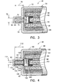
- an auto ignition system 70 is shown within an airbag inflator 48.
- the airbag inflator 48 is similar to the airbag inflator 10 of FIGS. 1 and 2 , and includes an elongated, generally cylindrical inflator housing 50 having a sidewall 52.
- An endwall 54 is located at a first end of the inflator 48 unitary with the sidewall 52 , and a mounting stud 56 extends from the endwall.
- An ignitor tube 58 is centrally located within the inflator housing 50 and contains a suitable powder primary ignitor material 60 .
- An end 61 of the ignitor tube 58 is closed with a suitable seal 62 such as a porous metal mesh seal or a solid metal foil seal, for example, and an open-ended rubber or metal cap 64.
- a suitable solid gas generant 66 Surrounding the ignitor tube 58 is a suitable solid gas generant 66 , which may be in the form of granules, disks or wafers for example, and surrounding the gas generant is a gas cooling and filter assembly 68 .
- the auto ignition system 70 includes a cylindrical, elongated auto ignition chamber 72 having an open end 74 .
- the auto ignition chamber 72 comprises a recess formed in the endwall 54 of the airbag inflator 48 and extending into the mounting stud 56 .
- a suitable auto ignition material 80 is a suitable auto ignition material 80.
- the auto ignition material 80 may be granule, powder or other suitable material which will auto ignite at a desired temperature of about 350°F (177°C) and produce a hot gas/particulate effluent.
- a suitable auto ignition material 80 is a nitro-cellulose based composition such as IMR 3031, a product of E.I. DuPont de Nemours Co.
- Closure means closes the open end 74 of the recess 72 and comprises a solid metal foil retention disk 82 which prevents the powder auto ignition material 80 from leaking out of the recess.
- the solid metal foil retention disk 82 which is shown with a larger thickness than actual for purposes of illustration, is secured to the endwall 54 of the inflator housing 50 , covering the open end 74 of the recess 72 , with an appropriate bonding material such as silicone, for example.
- the closure means can comprise a metal mesh weave retention disk, or perforated foil disk.
- the auto ignition chamber or recess 72 is sufficiently elongated to create a shotgun effect for the hot gas/particulate effluent created by the auto ignition material 80 when it is auto ignited within the recess.
- the recess 72 has a length 76 to width 78 ratio of at least three.
- shotgun effect it is meant that the elongated recess 72 will direct the expanding hot gas/particulate effluent towards the spaced-apart end 61 of the ignitor tube 58.
- shotgun effect it is also meant that the relatively small width 78 of the recess 72 will cause the expanding hot effluent to rush towards and squeeze out of the open end 74 of the recess so that the hot effluent is discharged from the recess with a greater velocity and greater force than the hot effluent produced by the existing auto ignition device 38 of FIG. 2 .
- the shotgun effect ensures that the hot effluent will be directed at and have a great enough range to strike the end 61 of the ignitor tube 58 and pass through the seal 62 of the ignitor tube to ignite the primary ignitor material 60 and initiate the airbag inflator 48 .
- the end 61 of the ignitor tube 58 is spaced-apart from the open end 74 of the recess 72 and does not have to be positioned directly adjacent the auto ignition system 70 to ensure that the hot gas/particulate effluent will reach the ignitor tube.
- the present invention does not require a tight assembly tolerance between the ignitor tube 58 and the auto ignition system 70 or an elaborate locator cap for positioning the end of the ignitor tube.
- the minimum distance required between the ignitor tube 58 and the auto ignition device 70 can be increased by increasing the length 76 of the recess 72 .
- the shotgun effect created by the elongated recess 72 also gives the hot effluent enough force to blow through the metal foil retention disk 82 and still remain directed towards the ignitor tube 58 .
- the present invention therefore, allows the use of a metal foil retention disk 82 as opposed to a metal mesh weave, or screen retention disk that could allow leakage of the fine granule auto ignition material 80.
- providing an auto ignition material 80 that produces a hot gas/particulate effluent having large pieces of particulate will additionally allow a solid metal foil seal to be used on the end 61 of the ignitor tube 58 in place of the metal mesh weave or screen seal 62.
- the large pieces of particulate will pierce the metal foil seal and expose the primary ignition material 60 to the hot gas/particulate effluent.
- the use of a solid seal on the end 61 of the ignitor tube 58 will reduce the chances of the primary ignitor material 60 leaking.
- the auto ignition system 70 can contain the same amount of auto ignition material 80 as the auto ignition device 38 of FIG. 2 and still produce a hot effluent having the desired greater range, as long as the auto ignition chamber or recess 72 is sufficiently elongated and preferably has a length 76 that is at least three times greater than the width 78 of the recess.
- an additional auto ignition system 84 is shown mounted within an airbag inflator 86.
- the airbag inflator 86 is similar to the airbag inflator 10 of FIG. 3, and includes an inflator housing 88 having a sidewall 90 .
- An endwall 92 is located at a first end of the inflator 86 , is unitary with the sidewall 90 and a mounting stud 94 extends from the endwall.
- An ignitor tube 96 is centrally located within the inflator housing 88 and contains a suitable powder primary ignitor material 98 .
- An end 100 of the ignitor tube 96 is closed with a suitable seal 62 such as a metal mesh weave seal or solid metal foil seal, for example, and an open-ended rubber or metal cap 64 .
- a suitable gas generant 104 Surrounding the ignitor tube 96 is a suitable gas generant 104, which may be in the form of granules, disks or wafers for example, and surrounding the gas generant is a gas cooling and filter assembly 106.
- the auto ignition system 84 includes a cylindrical, elongated auto ignition chamber 107 having an open end 110.
- the auto ignition chamber 107 is defined by an elongated, cylindrical retention cup 108 press-fit within a recess 116 defined by the endwall 92 of the inflator housing 88 and extending into the mounting stud 94 .
- An example of a similar retention cup is shown and described in U.S. Patent No. 5,378,017 which is assigned to the assignee of the present invention.
- the retention cup 108 includes a sidewall 118 , and an endwall 120 that closes and is preferably unitary with a first end 122 of the sidewall.
- a second end 124 of the sidewall 118 defines the open end 110 of the auto ignition chamber 107 .
- a flared neck 126 extends radially outwardly from the second end 124 of the sidewall 118, and a cylindrical, bendable flange 128 extends axially from the neck so that the inner diameter of the flange is greater than the inner diameter of the sidewall.
- the sidewall 118 of the retention cup 108 defines at least five, and preferably six equally spaced-apart, outwardly protruding elongated ribs 130.
- the ribs 130 which run axially along the retention cup 108, are for the press fit insertion of the retention cup into the recess 116 of the airbag inflator 86 . In general, such press fit insertion is effected as a result of the ribs 130 having a greater outside diameter than the diameter of the recess 116.
- the ribs 130 include a tapered lead surface 132 to facilitate insertion of the retention cup 108 within the recess 116. It is to be understood that the width of the ribs 130 can be appropriately altered so as to provide desired surface area contact between the ribs and the recess 116. The ribs 130 also provide a heat transfer path or thermal contact between the retention cup 108 and the inflator housing 88.
- the retention cup 108 is preferably a one-piece construction.
- the material of the retention cup 108 can be 0.010 inch (0.0254 cm)or more thick flat aluminum sheet stock or foil which is progressively punched to arrive at the final form. It is to be understood, however, that the retention cup 108 can be of a multi-piece construction such as wherein a flange 128 is joined to a sidewall 118, for example.
- closure means closes the open end 110 of the retention cup 108 and comprises a metal foil retention disk 136 which prevents the powder auto ignition material 134 from leaking.
- the closure means may comprise a metal mesh weave retention disk.
- the bendable flange 128 is crimped or appropriately bent over the metal foil retention disk 136 to secure the disk over the open end 110 of the retention cup 108.
- the auto ignition system 84 becomes a self-contained unit suitable for manual or automated assembly into the recess 116 of the airbag inflator 86.
- the auto ignition chamber 107 defined by the retention cup 108 is sufficiently elongated to create a shotgun effect for hot gas/particulate effluent created by the auto ignition material 134 when it is auto ignited within the cup.
- the auto ignition chamber 107 has a length 112 to width 114 ratio of at least three.
- shotgun effect it is meant that the relatively small width 114 or diameter of the auto ignition chamber 107 causes the expanding hot gas/particulate effluent to rush towards and squeeze out of the open end 110 of the chamber so that the hot effluent is discharged with a greater velocity and greater force than the effluent produced by the existing auto ignition device 38 of FIG. 2.
- an additional auto ignition system 138 is shown incorporated in an airbag inflator 140 that is similar to the airbag inflator 140 of FIG. 2 , and includes an elongated, generally cylindrical inflator housing 142 having a sidewall 144.
- An endwall 146 is unitary with a first end of the inflator 140, and a mounting stud 148 extends from the endwall.
- An ignitor tube 150 is centrally located within the inflator housing 142 and contains a suitable powder primary ignitor material 152 .
- An end 170 of the ignitor tube 156 is closed with a metal foil cap 172 .
- Surrounding the ignitor tube 150 is a gas generant 154 in suitable form, and surrounding the gas generant is a gas cooling and filter assembly 156 .
- the auto ignition system 138 includes a cylindrical, elongated auto ignition chamber 158 having an open end 160.
- the auto ignition chamber 158 comprises a recess defined by the endwall 146 of the airbag inflator 140 and extending into the mounting stud 148.
- Substantially filling the recess 158 is a suitable auto ignition material 166 similar to the auto ignition material in the auto ignition systems of FIGS. 3 through 6.
- the auto ignition chamber or recess 158 is sufficiently elongated to create a shotgun effect for hot gas/particulate effluent created by the auto ignition material 166 when it is auto ignited within the recess.
- the recess has a length 162 to width 164 ratio of at least three.
- shotgun effect it is meant that the relatively small width 164 or diameter of the recess 158 causes the expanding hot gas/particulate effluent to rush towards and squeeze out of the open end 160 of the recess so that the hot effluent is discharged with a greater velocity and greater force than the effluent produced by the existing auto ignition device 38 of FIG. 2.
- Closure means comprising a press-fit closure plug 168 closes the open end 160 of the recess 158 and prevents the powder auto ignition material 166 from leaking out of the open end of the recess.
- press-fit it is meant that the outside diameter of the press-fit closure plug 168 is slightly larger than the inside diameter of the recess 158 so that a small amount of deformation of the press-fit closure plug or the recess is required to securely position the closure plug within the open end 160 of the recess.
- the shotgun effect created by the sufficiently elongated recess 158 ensures that the hot gas/particulate effluent will have enough force to blow out or eject the press-fit closure plug 168.
- the press-fit closure plug 168 will resist being ejected until a threshold amount of pressure builds in the recess 158, contributing to the force of ejection.
- the shotgun effect created by the sufficiently elongated recess 158 also ensures that the hot gas/particulate effluent produced by the auto ignition material 166 will have enough range to reach the end 170 of the ignitor tube 150 that is spaced-apart from the open end 160 of the recess 158 . This reduces the assembly tolerances required between the end 170 of the ignitor tube 150 and the auto ignition system 138 .
- the press-fit closure plug 168 will pierce the metal foil cap 172 closing the end 170 of the ignitor tube 150 upon being ejected from the open end 160 of the recess 158 to allow the hot gas/particulate effluent to enter the ignitor tube and ignite the primary ignition material 166 .
- the press-fit closure plug 168 therefore, allows a solid cap 172, made from a suitable material such as solid metal foil, for example, to be used on the ignitor tube 150 as opposed to a metal mesh or screen seal, decreasing the chances that the fine granule primary ignitor material 152 will leak out of the ignitor tube.
- the auto ignition system 138 could additionally include a shock sensitive charge such as a primer, for example, secured to the end 170 of the ignitor tube 150.
- a shock sensitive charge such as a primer, for example, secured to the end 170 of the ignitor tube 150.
- the shock sensitive charge would be ignited by an ejected closure plug 168 striking the charge, and the charge would in-turn ignite the primary ignitor material 152 .
- the press-fit closure plug 168 can comprise a suitable solid inert metal such as steel, for example, or a solid pyrotechnic material such as magnesium, for example.
- a pyrotechnic press-fit closure plug 168 will be ignited by the ignited auto ignition material 166 at about the same time as the closure plug is ejected from the open end 160 of the recess 158 , and will enhance the caloric output of the auto ignition system 138.
- the press-fit closure plug 168 can also comprise a porous metal fiber or fused powder press-fit closure plug.
- the fiber or fused powder of such a press-fit closure plug 168 could be comprised of a suitable inert metal such as steel, for example, compressed or fused together by heating, or could be comprised of a suitable pyrotechnic material such as magnesium, for example, compressed together.
- the porous metal fiber or powder press-fit closure plug 168 creates a filter effect that allows a low pressure gas effluent from the auto ignition material 166 to very slowly vent out of the recess 158 rather than be trapped therein, without loss of the auto ignition material itself. Trapped effluent might possibly degrade, and shorten the useful life of, the auto ignition material 166.
- the filter effect created by the porous metal fiber or powder press-fit closure plug 168 also readily retains the fine granules of the powder auto ignition material 166 within the recess 158 .
- the metal fiber or powder closure plug 168 initially resists high temperature and pressure during ignition of the auto ignition material 166. This allows pressure to build within the recess 158, eventually causing the metal fiber or powder closure plug 168 to be ejected from the open end 160 of the recess to pierce the metal foil cap 172 on the end 170 of the ignitor tube 150.
- auto ignition systems of the present invention are shown in a specific embodiment of an airbag inflator, the auto ignition systems could be used in a number of different types and styles of airbag inflators.
- the auto ignition systems according to the present invention consequently, are not limited to use with the airbag inflators shown and described.
Landscapes
- Physics & Mathematics (AREA)
- Fluid Mechanics (AREA)
- Engineering & Computer Science (AREA)
- Mechanical Engineering (AREA)
- Air Bags (AREA)
Applications Claiming Priority (2)
| Application Number | Priority Date | Filing Date | Title |
|---|---|---|---|
| US61179796A | 1996-03-06 | 1996-03-06 | |
| US611797 | 1996-03-06 |
Publications (2)
| Publication Number | Publication Date |
|---|---|
| EP0794092A1 true EP0794092A1 (fr) | 1997-09-10 |
| EP0794092B1 EP0794092B1 (fr) | 2000-05-03 |
Family
ID=24450449
Family Applications (1)
| Application Number | Title | Priority Date | Filing Date |
|---|---|---|---|
| EP97301214A Expired - Lifetime EP0794092B1 (fr) | 1996-03-06 | 1997-02-25 | Système d'allumage automatique |
Country Status (4)
| Country | Link |
|---|---|
| US (1) | US5762370A (fr) |
| EP (1) | EP0794092B1 (fr) |
| JP (1) | JP3041188U (fr) |
| DE (1) | DE69701826T2 (fr) |
Families Citing this family (6)
| Publication number | Priority date | Publication date | Assignee | Title |
|---|---|---|---|---|
| US6709011B2 (en) * | 2001-02-21 | 2004-03-23 | Autoliv Asp, Inc. | Leak detection enhancing insert for an airbag inflator assembly |
| DE102007023043A1 (de) * | 2007-05-16 | 2008-11-20 | Trw Airbag Systems Gmbh | Gasgenerator |
| US8997655B1 (en) * | 2009-06-04 | 2015-04-07 | Tk Holdings Inc. | Gas generating system |
| DE102012209452B4 (de) * | 2012-06-05 | 2024-07-18 | Bayerische Motoren Werke Aktiengesellschaft | Verfahren in einem Kraftfahrzeug mit mindestens einem Antriebsmotor |
| JP5897417B2 (ja) * | 2012-07-13 | 2016-03-30 | 株式会社ダイセル | 点火器用のカバー部材 |
| US10677576B1 (en) * | 2015-12-30 | 2020-06-09 | Systima Technologies, Inc. | Multistage thermal trigger |
Citations (9)
| Publication number | Priority date | Publication date | Assignee | Title |
|---|---|---|---|---|
| DE3824469C1 (fr) * | 1988-07-19 | 1990-01-04 | Bayern-Chemie Gesellschaft Fuer Flugchemische Antriebe Mbh, 8012 Ottobrunn, De | |
| US5100170A (en) * | 1991-01-22 | 1992-03-31 | Trw Vehicle Safety Systems Inc. | Auto-ignition device for an air bag inflator |
| EP0488938A2 (fr) * | 1990-11-28 | 1992-06-03 | Dynamit Nobel Aktiengesellschaft | Génerateur de gaz, en particulier générateur de gaz tubulaire pour coussin d'air |
| US5186491A (en) * | 1990-06-29 | 1993-02-16 | Nippon Kayaku Kabushiki Kaisha | Auto ignition device |
| EP0552706A1 (fr) * | 1992-01-23 | 1993-07-28 | Dynamit Nobel Aktiengesellschaft | Installation de filtrage d'un courant de gaz |
| DE4234276C1 (de) * | 1992-10-10 | 1993-11-11 | Sk Jagd Und Sportmunitions Gmb | Gaserzeuger |
| EP0592254A1 (fr) * | 1992-10-09 | 1994-04-13 | Morton International, Inc. | Générateur de gaz pour système de retenue d'un occupant de véhicule |
| US5378017A (en) * | 1993-06-11 | 1995-01-03 | Morton International, Inc. | Auto ignition in gas generator |
| US5380039A (en) * | 1993-09-29 | 1995-01-10 | Trw Vehicle Safety Systems Inc. | Air bag inflator |
Family Cites Families (5)
| Publication number | Priority date | Publication date | Assignee | Title |
|---|---|---|---|---|
| US5409259A (en) * | 1992-10-09 | 1995-04-25 | Morton International, Inc. | Gas generator for vehicle occupant restraint system |
| US5350193A (en) * | 1993-06-22 | 1994-09-27 | Nippon Koki Co., Ltd. | Air bag inflation gas generator |
| US5427030A (en) * | 1993-10-12 | 1995-06-27 | Morton International, Inc. | Ignition granule retention disc |
| US5468017A (en) * | 1994-10-17 | 1995-11-21 | Trw Inc. | Auto ignition package for an air bag inflator |
| US5533754A (en) * | 1995-05-31 | 1996-07-09 | Trw Vehicle Safety Systems Inc. | Air bag inflator |
-
1997
- 1997-02-25 EP EP97301214A patent/EP0794092B1/fr not_active Expired - Lifetime
- 1997-02-25 DE DE69701826T patent/DE69701826T2/de not_active Expired - Fee Related
- 1997-03-05 JP JP1997001340U patent/JP3041188U/ja not_active Expired - Lifetime
- 1997-06-03 US US08/868,030 patent/US5762370A/en not_active Expired - Fee Related
Patent Citations (9)
| Publication number | Priority date | Publication date | Assignee | Title |
|---|---|---|---|---|
| DE3824469C1 (fr) * | 1988-07-19 | 1990-01-04 | Bayern-Chemie Gesellschaft Fuer Flugchemische Antriebe Mbh, 8012 Ottobrunn, De | |
| US5186491A (en) * | 1990-06-29 | 1993-02-16 | Nippon Kayaku Kabushiki Kaisha | Auto ignition device |
| EP0488938A2 (fr) * | 1990-11-28 | 1992-06-03 | Dynamit Nobel Aktiengesellschaft | Génerateur de gaz, en particulier générateur de gaz tubulaire pour coussin d'air |
| US5100170A (en) * | 1991-01-22 | 1992-03-31 | Trw Vehicle Safety Systems Inc. | Auto-ignition device for an air bag inflator |
| EP0552706A1 (fr) * | 1992-01-23 | 1993-07-28 | Dynamit Nobel Aktiengesellschaft | Installation de filtrage d'un courant de gaz |
| EP0592254A1 (fr) * | 1992-10-09 | 1994-04-13 | Morton International, Inc. | Générateur de gaz pour système de retenue d'un occupant de véhicule |
| DE4234276C1 (de) * | 1992-10-10 | 1993-11-11 | Sk Jagd Und Sportmunitions Gmb | Gaserzeuger |
| US5378017A (en) * | 1993-06-11 | 1995-01-03 | Morton International, Inc. | Auto ignition in gas generator |
| US5380039A (en) * | 1993-09-29 | 1995-01-10 | Trw Vehicle Safety Systems Inc. | Air bag inflator |
Also Published As
| Publication number | Publication date |
|---|---|
| US5762370A (en) | 1998-06-09 |
| DE69701826T2 (de) | 2000-08-17 |
| JP3041188U (ja) | 1997-09-09 |
| EP0794092B1 (fr) | 2000-05-03 |
| DE69701826D1 (de) | 2000-06-08 |
Similar Documents
| Publication | Publication Date | Title |
|---|---|---|
| US5623115A (en) | Inflator for a vehicle airbag system and a pyrogen igniter used therein | |
| JP4814082B2 (ja) | 自動車のエアバッグシステム用火薬式インフレータ | |
| US6199906B1 (en) | Dual stage pyrotechnic inflator | |
| US6908104B2 (en) | Pyrotechnic side impact inflator | |
| US6854764B2 (en) | Flexible airbag inflator | |
| EP0779187B1 (fr) | Allumeur pyrotechnique autonome pour générateur de gaz | |
| US5934705A (en) | Two chamber inflator body | |
| EP2383154B1 (fr) | Générateur de gaz | |
| KR100589993B1 (ko) | 팽창기 | |
| EP0836563B1 (fr) | Generateur a double chambre d'un gaz exempt de nitrure | |
| US5772243A (en) | Igniter for gas bag inflator | |
| US5542702A (en) | Pressurized gas inflator for vehicle occupant protection systems | |
| US7806954B2 (en) | Gas generator | |
| KR20010106140A (ko) | 가스발생기 | |
| US6139055A (en) | Adaptive heated stage inflator | |
| JP3702074B2 (ja) | ガス発生器 | |
| JPH11217055A (ja) | ガス発生器 | |
| JPH1178766A (ja) | エアバッグ用ガス発生器 | |
| EP0794092B1 (fr) | Système d'allumage automatique | |
| US5429386A (en) | Auto ignition device for an air bag inflator | |
| JP5734746B2 (ja) | ガス発生器 | |
| JPH0796814A (ja) | 車両の乗員拘束装置を膨張させるための装置、エアバッグ用混成型膨張装置および膨張ガス生成方法 | |
| EP0629529A1 (fr) | Dispositif d'auto-allumage pour générateur de gaz | |
| US11603072B2 (en) | Dual stage inflator | |
| WO2001074632A1 (fr) | Generateur de gaz |
Legal Events
| Date | Code | Title | Description |
|---|---|---|---|
| PUAI | Public reference made under article 153(3) epc to a published international application that has entered the european phase |
Free format text: ORIGINAL CODE: 0009012 |
|
| AK | Designated contracting states |
Kind code of ref document: A1 Designated state(s): DE FR GB IT |
|
| 17P | Request for examination filed |
Effective date: 19971027 |
|
| GRAG | Despatch of communication of intention to grant |
Free format text: ORIGINAL CODE: EPIDOS AGRA |
|
| 17Q | First examination report despatched |
Effective date: 19990430 |
|
| GRAG | Despatch of communication of intention to grant |
Free format text: ORIGINAL CODE: EPIDOS AGRA |
|
| GRAH | Despatch of communication of intention to grant a patent |
Free format text: ORIGINAL CODE: EPIDOS IGRA |
|
| GRAH | Despatch of communication of intention to grant a patent |
Free format text: ORIGINAL CODE: EPIDOS IGRA |
|
| RAP1 | Party data changed (applicant data changed or rights of an application transferred) |
Owner name: AUTOLIV ASP, INC. |
|
| GRAA | (expected) grant |
Free format text: ORIGINAL CODE: 0009210 |
|
| AK | Designated contracting states |
Kind code of ref document: B1 Designated state(s): DE FR GB IT |
|
| PG25 | Lapsed in a contracting state [announced via postgrant information from national office to epo] |
Ref country code: IT Free format text: LAPSE BECAUSE OF FAILURE TO SUBMIT A TRANSLATION OF THE DESCRIPTION OR TO PAY THE FEE WITHIN THE PRE;WARNING: LAPSES OF ITALIAN PATENTS WITH EFFECTIVE DATE BEFORE 2007 MAY HAVE OCCURRED AT ANY TIME BEFORE 2007. THE CORRECT EFFECTIVE DATE MAY BE DIFFERENT FROM THE ONE RECORDED.SCRIBED TIME-LIMIT Effective date: 20000503 Ref country code: FR Free format text: LAPSE BECAUSE OF FAILURE TO SUBMIT A TRANSLATION OF THE DESCRIPTION OR TO PAY THE FEE WITHIN THE PRESCRIBED TIME-LIMIT Effective date: 20000503 |
|
| REF | Corresponds to: |
Ref document number: 69701826 Country of ref document: DE Date of ref document: 20000608 |
|
| EN | Fr: translation not filed | ||
| PLBE | No opposition filed within time limit |
Free format text: ORIGINAL CODE: 0009261 |
|
| STAA | Information on the status of an ep patent application or granted ep patent |
Free format text: STATUS: NO OPPOSITION FILED WITHIN TIME LIMIT |
|
| 26N | No opposition filed | ||
| REG | Reference to a national code |
Ref country code: GB Ref legal event code: IF02 |
|
| PGFP | Annual fee paid to national office [announced via postgrant information from national office to epo] |
Ref country code: GB Payment date: 20070131 Year of fee payment: 11 |
|
| PGFP | Annual fee paid to national office [announced via postgrant information from national office to epo] |
Ref country code: DE Payment date: 20070228 Year of fee payment: 11 |
|
| GBPC | Gb: european patent ceased through non-payment of renewal fee |
Effective date: 20080225 |
|
| PG25 | Lapsed in a contracting state [announced via postgrant information from national office to epo] |
Ref country code: DE Free format text: LAPSE BECAUSE OF NON-PAYMENT OF DUE FEES Effective date: 20080902 |
|
| PG25 | Lapsed in a contracting state [announced via postgrant information from national office to epo] |
Ref country code: GB Free format text: LAPSE BECAUSE OF NON-PAYMENT OF DUE FEES Effective date: 20080225 |