EP0794108A1 - Anpassungsteil zum Fixieren eines kleineren Notrades in seinem Behälter in einem Kraftfahrzeug - Google Patents
Anpassungsteil zum Fixieren eines kleineren Notrades in seinem Behälter in einem Kraftfahrzeug Download PDFInfo
- Publication number
- EP0794108A1 EP0794108A1 EP97400072A EP97400072A EP0794108A1 EP 0794108 A1 EP0794108 A1 EP 0794108A1 EP 97400072 A EP97400072 A EP 97400072A EP 97400072 A EP97400072 A EP 97400072A EP 0794108 A1 EP0794108 A1 EP 0794108A1
- Authority
- EP
- European Patent Office
- Prior art keywords
- floor
- wheel
- vehicle
- rod
- rods
- Prior art date
- Legal status (The legal status is an assumption and is not a legal conclusion. Google has not performed a legal analysis and makes no representation as to the accuracy of the status listed.)
- Granted
Links
- 239000013013 elastic material Substances 0.000 claims description 5
- 230000003100 immobilizing effect Effects 0.000 claims description 3
- 235000012771 pancakes Nutrition 0.000 description 11
- 238000003466 welding Methods 0.000 description 3
- 239000002184 metal Substances 0.000 description 2
Images
Classifications
-
- B—PERFORMING OPERATIONS; TRANSPORTING
- B62—LAND VEHICLES FOR TRAVELLING OTHERWISE THAN ON RAILS
- B62D—MOTOR VEHICLES; TRAILERS
- B62D43/00—Spare wheel stowing, holding, or mounting arrangements
- B62D43/02—Spare wheel stowing, holding, or mounting arrangements external to the vehicle body
- B62D43/04—Spare wheel stowing, holding, or mounting arrangements external to the vehicle body attached beneath the vehicle body
Definitions
- the present invention relates to an adapter intended to immobilize a spare wheel of the wafer type, for a motor vehicle, in a housing intended to receive and immobilize a normal wheel.
- car manufacturers sometimes supply vehicles with a spare wheel of the pancake type, that is to say the part forming the tire is axially less wide and radially thinner than the tire d '' a normal wheel used under normal conditions of movement of the vehicle.
- the rim of such a pancake type wheel is axially narrower than a normal wheel and has a larger diameter than the rim of the normal wheel in order to obtain an overall diameter of the pancake type wheel substantially. equal to that of a normal inflated wheel.
- the pancake type wheel is removed from its housing, then a punctured normal type wheel is inserted and held in the housing.
- the housing must be dimensioned to receive a normal type wheel.
- the problem therefore consists in being able to immobilize a wheel of the pancake type in a housing provided for immobilizing a normal wheel in order to avoid noise and vibrations when the wheel of the pancake type is placed in the housing.
- this housing When the housing intended to receive the normal type or pancake type wheel is provided under the vehicle floor, generally at the rear thereof, this housing is most often delimited by the vehicle floor and / or a cross member located below this floor, and a wheel support mounted tilting around a horizontal axis between a high position of immobilization against the floor of the normal type wheel or wafer type and an access position inside the housing to remove or set up this wheel.
- This adapter consists of a metal wire forming a pin folded in a general U shape, the base and the free ends of the branches of the pin are received in a circumferential groove of the rim of the wafer type wheel.
- This pin-shaped adapter allows you to apply the wafer type wheel to its support and also to be able to carry it like a handle of a basket.
- this adapter is sized to rest against the vehicle floor.
- the object of the invention is to avoid these drawbacks by proposing an adapter intended to immobilize a spare wheel of the pancake type in a housing intended to receive and immobilize a normal type wheel which is particularly easy to install.
- the subject of the invention is an adapter intended to immobilize a spare wheel of the pancake type, for a motor vehicle, in a housing intended to receive and immobilize a normal wheel, the housing comprising a support mounted tilting under the floor of the vehicle between a high immobilization position of the normal wheel or of the pancake type wheel, and a low position for access to the interior of the housing, characterized in that it comprises a set of rods connected to one another at one of their ends and the other end of which is fixed to the floor of the vehicle, said rods being shaped to apply the wafer type wheel against the support.
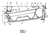
- a motor vehicle floor 1 has been shown diagrammatically comprising in particular a cross member 2 extending transversely with respect to the longitudinal direction of said vehicle and located below the floor 1.
- a housing 3 intended to receive a spare wheel 4 of the wafer type.
- the housing 3 is also designed to receive a normal wheel, that is to say normally used on the vehicle, whether the latter is inflated, punctured or flat.
- the housing 3 is equipped with a support 5 formed for example of a metal rod bent in the shape of a hairpin, the free ends 5a of the branches of which are inclined upward relative to the general plane of the hairpin, to deviate from it.
- a support 5 formed for example of a metal rod bent in the shape of a hairpin, the free ends 5a of the branches of which are inclined upward relative to the general plane of the hairpin, to deviate from it.
- the base 5b of the pin is received in the end of a hook 7 suspended from the floor 1, the distance between the end of the hook 7 and the floor 1 being adjustable using a screw 8 whose head is located above the floor 1, in the trunk of the vehicle for example.
- a retaining member 9 is also provided for holding the support 5 in an intermediate position when the screw 8 is actuated in the direction away from the end of the hook 7 from the floor 1, so as to be able at first to release the end support 5.
- the retaining member 9 is elastically deformable so as to be able to be released from the support 5 then allowing the latter to tilt around the free ends 5a articulated on the legs 6, until the base of the support 5 comes into contact with the ground , allowing access to the housing 3 and thus to the wheel 4 located above the support 5.
- the axial dimension of a spare wheel of the wafer type is much smaller than the axial dimension of the rim of a normal wheel.
- an adapter 10 is interposed between the floor 1, the cross member 2 and the spare wheel 4 of the wafer type.
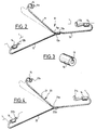
- the adapter 10 shown in Figures 2 and 4 comprises a set of rods connected together at one of their ends and the other end of which is fixed to the floor 1 of the vehicle.
- the adapter 10 comprises three rods, respectively 11, 12 and 13, forming a Y.
- the end 11a of the rod 11 is connected for example by welding to the end 12a of the rod 12 and the ends 11a and 12a are connected for example by welding to the end 13a of the rod 13 to produce a set of three rods 11, 12 and 13 having the shape of a Y.
- the free ends, respectively 11b, 12b and 13b of the rods 11, 12 and 13, are bent upwards and have the shape of a hook intended to each penetrate into a hole 25 made in the floor 1 of the motor vehicle.
- the rods 11, 12 and 13 are shaped to apply the spare wheel 4 of the wafer type when it is placed on the support 5 and that this support 5 is in the high immobilization position of this wheel 4, as shown in FIG. . 1.
- each rod 11, 12 and 13 is in contact with the wheel 4 of the wafer type in the vicinity of its end 11b, 12b and 13b fixed to the floor 1 of the motor vehicle.
- the rods 11, 12 and 13 of the adapter 10 are therefore detachably fixed to the floor 1 of the motor vehicle, by means of the ends 11b, 12b and 13b in the form of a hook, which makes it possible to be able to install or remove this adapter. 10 depending on the wheel placed in the housing 3.
- each rod 11, 12 and 13 comprises, in the vicinity of its end 11b, 12b and 13b fixed to the floor 1 of the vehicle, at least one stop 14 made of elastic material intended to rest on said floor 1 as shown in FIG. 1.
- each stop 14 has the shape of a sleeve provided with a longitudinal slot 15 and each sleeve 14 is threaded onto the end of the corresponding rod 11, 12 and 13.
- one end, for example 11b, of the rod 11 is placed in the corresponding hole 25 in the floor 1 by exerting on this rod 11 a pull perpendicular to its axis, as shown in dashed lines in FIG. 2.
- This arrangement avoids ejection of the adapter 10 in the event of significant vibrations, in particular when the housing 3 has no wheel.
- the adapter 20 is formed by two rods 21 and 22 forming a Y.
- the rod 21 has a bend 21a at its point of connection with the end 22a of the rod 22 and this end 22a is fixed at the level of this bend 21a of the rod 21 for example by welding.
- the rods 21 and 22 are removably attached to the floor 1 of the vehicle and for this purpose the free ends 21b and 21c of the rod 21 are bent upwards and have the shape of a hook, while the free end 22b rod 22 is also bent upwards and has the shape of a hook.
- the ends 21b, 21c and 22b respectively of the rods 21 and 22 are intended each to penetrate into a hole 25 made in the floor 1 of the vehicle.
- each rod 21 and 22 is in contact with the spare wheel 4 of the wafer type in the vicinity of the ends fixed to said floor 1.
- each rod 21 and 22 comprises, in the vicinity of the ends 21b, 22b and 21c fixed to the floor 1, at least one stop 14 made of elastic material intended to rest on said floor 1 when the adapter 20 is mounted below said floor 1, as shown in FIG. 1.
- the stop 14 has the form of a sleeve provided with a longitudinal slot 15 as shown in FIG. 3.
- the end, for example 21b, of the rod 21 is placed in the corresponding hole 25 in the floor 1 by exerting on this rod 21 a pull perpendicular to its axis, as shown in phantom on Fig. 4, which makes it possible to prevent this adapter from becoming detached from the floor 1 in the event of significant vibrations and in particular when the housing 3 does not have a wheel.
- the adapter 10 or 20 consisting of a set of rods forming a Y allows support in a stable plane and accepts any angular position of the spare wheel 4 of the wafer type in the housing 3.
- the adapter according to the invention which has the advantage of being particularly easy to mount in the housing provided below the vehicle floor, makes it possible to immobilize a spare wheel of the pancake type in this housing also provided for a normal wheel.
Landscapes
- Engineering & Computer Science (AREA)
- Chemical & Material Sciences (AREA)
- Combustion & Propulsion (AREA)
- Transportation (AREA)
- Mechanical Engineering (AREA)
- Handcart (AREA)
- Body Structure For Vehicles (AREA)
Applications Claiming Priority (2)
| Application Number | Priority Date | Filing Date | Title |
|---|---|---|---|
| FR9602831A FR2745780B1 (fr) | 1996-03-06 | 1996-03-06 | Adaptateur d'immobilisation d'une roue de secours de type galette dans un logement de roue normale |
| FR9602831 | 1996-03-06 |
Publications (2)
| Publication Number | Publication Date |
|---|---|
| EP0794108A1 true EP0794108A1 (de) | 1997-09-10 |
| EP0794108B1 EP0794108B1 (de) | 2000-03-29 |
Family
ID=9489921
Family Applications (1)
| Application Number | Title | Priority Date | Filing Date |
|---|---|---|---|
| EP19970400072 Expired - Lifetime EP0794108B1 (de) | 1996-03-06 | 1997-01-15 | Anpassungsteil zum Fixieren eines kleineren Notrades anstelle eines Rades mit Standardgrösse an einem Kraftfahrzeug |
Country Status (3)
| Country | Link |
|---|---|
| EP (1) | EP0794108B1 (de) |
| DE (1) | DE69701541T2 (de) |
| FR (1) | FR2745780B1 (de) |
Cited By (2)
| Publication number | Priority date | Publication date | Assignee | Title |
|---|---|---|---|---|
| WO2009068765A1 (fr) * | 2007-11-29 | 2009-06-04 | Renault S.A.S | Dispositif de fixation d'une roue de secours d'un vehicule automobile |
| DE102008003642A1 (de) | 2008-01-09 | 2009-07-16 | GM Global Technology Operations, Inc., Detroit | Reserveradhalterung und Montage für ein Fahrzeug |
Citations (3)
| Publication number | Priority date | Publication date | Assignee | Title |
|---|---|---|---|---|
| FR1092433A (fr) * | 1953-10-22 | 1955-04-21 | Support basculant pour roue de secours | |
| EP0201414A1 (de) * | 1985-05-06 | 1986-11-12 | Automobiles Peugeot | Verstaueinrichtung eines Reserverades, flach oder normal unter einem Fahrzeugboden |
| FR2675762A1 (fr) * | 1991-04-25 | 1992-10-30 | Peugeot | Adaptateur pour immobilisation d'une roue de type galette dans un logement de roue normale. |
-
1996
- 1996-03-06 FR FR9602831A patent/FR2745780B1/fr not_active Expired - Fee Related
-
1997
- 1997-01-15 EP EP19970400072 patent/EP0794108B1/de not_active Expired - Lifetime
- 1997-01-15 DE DE1997601541 patent/DE69701541T2/de not_active Expired - Fee Related
Patent Citations (3)
| Publication number | Priority date | Publication date | Assignee | Title |
|---|---|---|---|---|
| FR1092433A (fr) * | 1953-10-22 | 1955-04-21 | Support basculant pour roue de secours | |
| EP0201414A1 (de) * | 1985-05-06 | 1986-11-12 | Automobiles Peugeot | Verstaueinrichtung eines Reserverades, flach oder normal unter einem Fahrzeugboden |
| FR2675762A1 (fr) * | 1991-04-25 | 1992-10-30 | Peugeot | Adaptateur pour immobilisation d'une roue de type galette dans un logement de roue normale. |
Cited By (4)
| Publication number | Priority date | Publication date | Assignee | Title |
|---|---|---|---|---|
| WO2009068765A1 (fr) * | 2007-11-29 | 2009-06-04 | Renault S.A.S | Dispositif de fixation d'une roue de secours d'un vehicule automobile |
| FR2924398A1 (fr) * | 2007-11-29 | 2009-06-05 | Renault Sas | Dispositif de fixation d'une roue de secours d'un vehicule automobile |
| DE102008003642A1 (de) | 2008-01-09 | 2009-07-16 | GM Global Technology Operations, Inc., Detroit | Reserveradhalterung und Montage für ein Fahrzeug |
| US8371485B2 (en) | 2008-01-09 | 2013-02-12 | GM Global Technology Operations LLC | Spare tire holder and installation for a vehicle |
Also Published As
| Publication number | Publication date |
|---|---|
| EP0794108B1 (de) | 2000-03-29 |
| DE69701541D1 (de) | 2000-05-04 |
| FR2745780A1 (fr) | 1997-09-12 |
| FR2745780B1 (fr) | 1998-05-29 |
| DE69701541T2 (de) | 2000-10-19 |
Similar Documents
| Publication | Publication Date | Title |
|---|---|---|
| EP0497655B1 (de) | Radzierblende, insbesondere für Kraftfahrzeuge | |
| EP0313520B1 (de) | Rutschsicherungsvorrichtung für Fahrzeugräder | |
| EP0794108B1 (de) | Anpassungsteil zum Fixieren eines kleineren Notrades anstelle eines Rades mit Standardgrösse an einem Kraftfahrzeug | |
| EP4415929A1 (de) | Einrichtung zum halten eines zwei- oder dreirädrigen rollenden fahrzeugs zur durchführung eines eingriffs an dem fahrzeug | |
| EP3007929B1 (de) | Fussstütze mit mitteln zur aufbewahrung von reifenreparaturausrüstung | |
| EP0296939B1 (de) | Vordere Mittelarmlehne mit zwei stabilen Lagen für Kraftfahrzeuge | |
| FR3119826A1 (fr) | Ensemble comprenant un élément de carénage destiné à être monté sous caisse dans un véhicule automobile, et au moins une pièce de fixation de l’élément de carénage | |
| EP0697327A1 (de) | Festhaltevorrichtung für den Reserveradkorb eines Kraftfahrzeugs | |
| FR2666775A1 (fr) | Dispositif de fixation d'un cycle pourvu d'une selle sur un support equipant un vehicule automobile. | |
| EP2300243B1 (de) | Vorrichtung zur befestigung eines kugellagers an einer welle | |
| FR3006286A1 (fr) | Dispositif de fixation a cable d'une roue de secours sous le plancher d'un vehicule | |
| FR3002192A1 (fr) | Dispositif de maintien du passe plancher des cables d'une commande de boite de vitesses lors de l'operation de « coiffage » de la carrosserie sur une ligne de montage de vehicules | |
| FR2675762A1 (fr) | Adaptateur pour immobilisation d'une roue de type galette dans un logement de roue normale. | |
| FR2525536A1 (de) | ||
| FR2809063A1 (fr) | Porte-velo pour vehicule automobile | |
| FR3093955A1 (fr) | Véhicule automobile à châssis inclinable | |
| FR2547255A1 (fr) | Element de separation des volumes reserves aux passagers avant et arriere d'une automobile | |
| EP0769446A1 (de) | Vorrichtung zum Fixieren eines Ersatzrads in seinem Behälter in einem Kraftfahrzeug | |
| EP1907739B1 (de) | Anordnung zur anbringung unter einer befestigten halterung, wie kraftfahrzeug-gehäuseboden und verfahren zur benutzung derselben | |
| EP0351261B1 (de) | Vorrichtung zur Befestigung eines Elementes auf der Aussenseite eines Hohlkörpers | |
| FR2798958A1 (fr) | Dispositif de securite | |
| FR3163918A1 (fr) | Accessoire, dit diabolo, pour engin à au moins deux roues, dispositif et procédé de maintien comprenant un tel accessoire | |
| EP1097851A1 (de) | Feststellbremsgehäuse für ein Kraftfahrzeug und Montageverfahren dieses Gehäuses | |
| FR2711422A1 (fr) | Dispositif de fixation d'appareil sur jante de roue de véhicule. | |
| FR3144641A1 (fr) | Moyen de fixation d’un tuyau flexible pour véhicule automobile |
Legal Events
| Date | Code | Title | Description |
|---|---|---|---|
| PUAI | Public reference made under article 153(3) epc to a published international application that has entered the european phase |
Free format text: ORIGINAL CODE: 0009012 |
|
| AK | Designated contracting states |
Kind code of ref document: A1 Designated state(s): DE GB IT |
|
| 17P | Request for examination filed |
Effective date: 19980302 |
|
| GRAG | Despatch of communication of intention to grant |
Free format text: ORIGINAL CODE: EPIDOS AGRA |
|
| RTI1 | Title (correction) |
Free format text: ADAPTER FOR FIXING A NARROWER SPARE TYRE AT THE PLACE OF A STANDARD SIZED TYRE OF AN AUTOMOBILE |
|
| 17Q | First examination report despatched |
Effective date: 19990728 |
|
| GRAG | Despatch of communication of intention to grant |
Free format text: ORIGINAL CODE: EPIDOS AGRA |
|
| GRAH | Despatch of communication of intention to grant a patent |
Free format text: ORIGINAL CODE: EPIDOS IGRA |
|
| GRAH | Despatch of communication of intention to grant a patent |
Free format text: ORIGINAL CODE: EPIDOS IGRA |
|
| GRAA | (expected) grant |
Free format text: ORIGINAL CODE: 0009210 |
|
| AK | Designated contracting states |
Kind code of ref document: B1 Designated state(s): DE GB IT |
|
| REF | Corresponds to: |
Ref document number: 69701541 Country of ref document: DE Date of ref document: 20000504 |
|
| ITF | It: translation for a ep patent filed | ||
| GBT | Gb: translation of ep patent filed (gb section 77(6)(a)/1977) |
Effective date: 20000515 |
|
| PLBE | No opposition filed within time limit |
Free format text: ORIGINAL CODE: 0009261 |
|
| STAA | Information on the status of an ep patent application or granted ep patent |
Free format text: STATUS: NO OPPOSITION FILED WITHIN TIME LIMIT |
|
| 26N | No opposition filed | ||
| REG | Reference to a national code |
Ref country code: GB Ref legal event code: IF02 |
|
| REG | Reference to a national code |
Ref country code: GB Ref legal event code: 746 Effective date: 20070119 |
|
| PGFP | Annual fee paid to national office [announced via postgrant information from national office to epo] |
Ref country code: IT Payment date: 20080122 Year of fee payment: 12 |
|
| PGFP | Annual fee paid to national office [announced via postgrant information from national office to epo] |
Ref country code: DE Payment date: 20090129 Year of fee payment: 13 |
|
| PGFP | Annual fee paid to national office [announced via postgrant information from national office to epo] |
Ref country code: GB Payment date: 20081229 Year of fee payment: 13 |
|
| GBPC | Gb: european patent ceased through non-payment of renewal fee |
Effective date: 20100115 |
|
| PG25 | Lapsed in a contracting state [announced via postgrant information from national office to epo] |
Ref country code: DE Free format text: LAPSE BECAUSE OF NON-PAYMENT OF DUE FEES Effective date: 20100803 |
|
| PG25 | Lapsed in a contracting state [announced via postgrant information from national office to epo] |
Ref country code: GB Free format text: LAPSE BECAUSE OF NON-PAYMENT OF DUE FEES Effective date: 20100115 |
|
| PG25 | Lapsed in a contracting state [announced via postgrant information from national office to epo] |
Ref country code: IT Free format text: LAPSE BECAUSE OF NON-PAYMENT OF DUE FEES Effective date: 20090115 |