EP0794129A1 - Verschlussvorrichtung für einen Behälter,insbesondere für ein medizinisches Fläschchen - Google Patents
Verschlussvorrichtung für einen Behälter,insbesondere für ein medizinisches Fläschchen Download PDFInfo
- Publication number
- EP0794129A1 EP0794129A1 EP97400492A EP97400492A EP0794129A1 EP 0794129 A1 EP0794129 A1 EP 0794129A1 EP 97400492 A EP97400492 A EP 97400492A EP 97400492 A EP97400492 A EP 97400492A EP 0794129 A1 EP0794129 A1 EP 0794129A1
- Authority
- EP
- European Patent Office
- Prior art keywords
- capsule
- intermediate piece
- neck
- skirt
- face
- Prior art date
- Legal status (The legal status is an assumption and is not a legal conclusion. Google has not performed a legal analysis and makes no representation as to the accuracy of the status listed.)
- Withdrawn
Links
Images


Classifications
-
- B—PERFORMING OPERATIONS; TRANSPORTING
- B65—CONVEYING; PACKING; STORING; HANDLING THIN OR FILAMENTARY MATERIAL
- B65D—CONTAINERS FOR STORAGE OR TRANSPORT OF ARTICLES OR MATERIALS, e.g. BAGS, BARRELS, BOTTLES, BOXES, CANS, CARTONS, CRATES, DRUMS, JARS, TANKS, HOPPERS, FORWARDING CONTAINERS; ACCESSORIES, CLOSURES, OR FITTINGS THEREFOR; PACKAGING ELEMENTS; PACKAGES
- B65D51/00—Closures not otherwise provided for
- B65D51/002—Closures to be pierced by an extracting-device for the contents and fixed on the container by separate retaining means
Definitions
- the present invention relates to a closure device for a container such as in particular a vial for medical use.
- Vials for medical use such as those used to carry out infusions or intended to contain any other injectable medication are generally provided with a sealing stopper made of elastic material, perforable in its central area by a hollow needle or a trocar, said stopper being held in position by a capsule which can be crimped or clipped onto the neck of the bottle, and having a detachable cover intended to make the central area of the stopper accessible.
- a sealing stopper made of elastic material, perforable in its central area by a hollow needle or a trocar, said stopper being held in position by a capsule which can be crimped or clipped onto the neck of the bottle, and having a detachable cover intended to make the central area of the stopper accessible.
- the present invention relates more particularly to a closure device for a bottle, the neck of which is provided, close to its opening edge, with an annular bead, said device comprising a capsule intended to be clipped or snapped onto the neck. by engagement under said bead.
- This device which consists of a single piece of plastic material produced by molding, makes it possible to avoid the problems resulting from the use of crimpable metal capsules, in particular allowing the easy removal of the capsules and the subsequent recycling of the bottles without risk of cutting for the user.
- the distance between the free end of the rib of the capsule and the upper face of the latching means of the skirt (constituted by a shoulder bearing the reference number 10 on the Figure 2 of the document FR 2.698.613) must be less than the distance separating the lower face of the bead from the neck and the upper face of the stopper in the plugged position inside the neck.
- the snap-fastening of the capsule on the neck causes the upper face of the shoulder 10 of the skirt to come into contact with the lower face of the bead of the neck, and consequently, the bearing of the rib 13 on the upper face of the plug.
- the thickness of the bead of the neck of the bottle as well as the thickness of the flange of the stopper can vary relatively appreciably.
- the closing force developed by the capsule and applying to the sealing plug can vary within very large proportions and in certain cases lead to a loss of sealing of the device described in the document FR 2,698,613.
- the tamper-evident ring of the device described in this prior document is located in the zone defined between the latching means of the skirt (shoulder 10) on the neck and the rib (13) of the capsule and defined by two substantially parallel rupture lines provided on the side wall of the capsule.
- This conformation therefore has the effect of reducing the mechanical resistance of the skirt of the capsule near the latching zone, which further increases the risks of loss of tightness during latching.
- the object of the present invention is to solve the technical problem consisting in the supply of a closure device of a new design, which is simple to produce and to implement on a scale. industrial and whose sealing is not likely to be affected by the dimensional variations of the neck of the bottle, the sealing cap or the parts constituting it.
- the invention therefore provides a simple and safe means for compensating for dimensional variations in the neck of the bottle and the sealing cap.
- the aforementioned skirt is connected to its lower part, by means of a set of connections angularly spaced tear-offs, to a tamper-evident ring whose internal face is provided with protruding elements forming notches intended to cooperate with elements forming notches carried by the intermediate piece and shaped so that the unscrewing of said capsule necessarily causes the tearing of said tearable links.
- the internal face of the continuous wall of the intermediate piece carries angularly spaced projecting elements, preferably extending substantially axially and intended to bear elastically against the lateral surface of the flange of the stopper. prevent the rotation of the intermediate piece when the capsule is screwed onto it.
- FIG. 1 therefore represents the end of the body of a container 1 for medical use containing, for example, an injectable product, and equipped with a sealing plug.
- This container can be a bottle or a flexible bag of the type used for transfusions, or any other bottle for medical use.
- the neck 2 of the bottle 1 is provided, near its opening edge 3 with a bead or annular bulge 4 defined by a shoulder 5 on the outside surface of the neck 2.
- the sealing plug 6 is produced in a manner known per se from a flexible and elastic material such as for example a rubber and comprises a substantially cylindrical part 7 intended to be engaged in the bore of the neck 2 and an upper flange 8 intended to come to bear on the opening edge 3 of the neck 2.
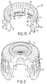
- closure device according to the invention and in particular its capsule and its intermediate part.
- the capsule generally represented by the reference numeral 10 (see FIG. 1B) has an upper bottom 11 substantially in the form of a disc and a substantially cylindrical skirt 12.
- the bottom 11 is provided with a detachable cover 13 which, in the example shown, is delimited by a rupture line 14, which is substantially circular.
- This cover is also connected to a gripping member such as a ring 15 rigidly connected to the bottom 11, for example by means of at least one vertical stud 16.
- the detachable cover can for example be produced in the form of an attached piece, fixed for example by bonding to the base 11, the latter being provided in this case with an opening for access to the central zone of the plug intended to be covered in a sealed manner by said cover.
- a cover may possibly be made of aluminum.
- the bottom 11 also includes an annular rib 17 projecting internally and intended to bear elastically against the upper face of the flange 8 of the plug 6.
- this rib 17 is arranged to be substantially opposite the opening edge 3 of the neck 2 (see FIG. 2B), in the position of use.
- the skirt 12 has, on its internal face, a thread 18 which extends substantially over its entire height.
- skirt 12 is connected to its lower part constituting the opening edge of the capsule, by means of a set of tear-away connections 19, angularly spaced, to a tamper-evident ring 20.
- This ring 20 is arranged coaxially radially and externally relative to the skirt 12.
- the tamper-evident ring 20 is provided, on its internal face, with a set of projecting elements forming notches 21 angularly spaced, preferably in a regular manner, and the function of which will be explained below.
- projecting elements 21 extend substantially axially (that is to say parallel to the median axis of the skirt) preferably in the extension of the tear-off connections connecting the tamper-evident ring 20 to the skirt 12.
- the external surface of the skirt 12 is advantageously provided with raised portions extending substantially axially, parallel to one another and intended to facilitate gripping of the capsule 10 in order to make it easier to screw it onto the intermediate piece.
- the intermediate piece 30 (FIG. 1C) generally has the form of a cylindrical sleeve intended to be disposed, in the position of use, between the neck 2 of the bottle and the skirt 12 of the capsule 10 (FIG. 3A).
- the intermediate part 30 comprises a lower part generally constituted by a set of elastic tongues 31 angularly spaced, preferably in a regular manner, and extending axially parallel to each other.
- tongues 31 are provided on their internal face with means of snap-fastening on the neck 2 by engagement under the annular bead 4.
- these snap-fastening means consist of lugs or bosses 32 shaped to cooperate with the shoulder 5 defining the annular bead 4.
- the bosses 32 have an upper side having a concave curve, while the shoulder 5 of the bead 4 has in longitudinal section a shape slightly inclined from the outside inwards and downwards.
- the bosses and the shoulder 5 cooperate as is understood by “wedge effect” and allow the latching or clipping of the intermediate piece 30 on the neck 2.
- the lower part of the intermediate piece 30 is of course radially deformable inwardly, due to the openings separating two successive tabs.
- the intermediate part 30 also comprises an upper part constituted by a substantially continuous (that is to say solid) wall 33 having on its external face a thread 34.
- the thread 34 has three threads and is adapted to allow the capsule 10 to be screwed onto the intermediate piece 30.
- Each tongue 31 of the intermediate piece 30 carries on its external face one or more (preferably two) notch-forming elements 36, extending in a plane substantially perpendicular to the median axis of the intermediate piece 30.
- the notches 36 of the intermediate piece 30 are intended to cooperate with the notches 21 provided on the internal face of the tamper-evident ring 30 with which they have complementary shapes.
- each notch 36 carried by a tongue 31 comprises, relative to the direction of rotation F (see FIG. 4) corresponding to the direction of screwing of the capsule 10 on the intermediate piece 30, a front face 37 inclined at an acute angle relative to the tangent T passing through the foot of said notch, and a substantially radial rear face 38.
- each notch 21 carried by the internal face of the tamper-evident ring 20 comprises an inclined front face 39 and a substantially radial rear face 40.
- the notch 21 When passing from the top 41 of the notch 36, the notch 21 is retracted into the space separating two successive notches 36.
- the presence of the ring 20 on the closure device according to the invention is a means of guarantee making it possible to reveal any attempt to remove the capsule 10 and therefore to access the contents of the bottle.
- the capsule 10 and the intermediate part 30 can be easily produced by injection molding using a thermoplastic material.
- This material will be chosen to withstand the high temperatures used during the sterilization of these medical containers.
- a material can for example be a polyethylene.
- the intermediate part 30 is first snapped or clipped onto the neck 2 provided with its sealing plug 6, the bosses 32 coming to be housed under the shoulder 5 of the bead 4. This operation can be carried out by a Automatic machine.
- the skirt 10 is then screwed onto the intermediate part 30, causing the approximation, then bringing the rib 17 into contact with the front 11 and the upper face of the flange 8 of the plug 6 (FIGS. 3A and 3B).
- the force exerted during screwing can be easily calculated so that the rib 17 exerts on the plug 6 sufficient pressure to ensure a good seal, especially at the level of the contact surface between the opening edge 3 of the neck and the flange 8 of the plug, regardless of the height of the bead 4 and the height of the flange 8 of the plug, within the manufacturing tolerances of these parts.
- the skirt 10 can be partially pre-screwed on the intermediate piece 30 before the assembly thus formed is mounted on the neck 2 of the container.
- the intermediate part 30 can be provided on its external surface with several (for example two) breakable pins angularly distributed, preferably in a regular manner, and arranged in the vicinity and under the thread 34, said pins being intended to cooperate with housings conformed for this purpose under the thread of the skirt 10, in order to determine a pre-assembly position.
- several (for example two) breakable pins angularly distributed, preferably in a regular manner, and arranged in the vicinity and under the thread 34, said pins being intended to cooperate with housings conformed for this purpose under the thread of the skirt 10, in order to determine a pre-assembly position.
- the skirt is provided on the intermediate piece 30 to a position where the aforementioned pins are received in said cavities.
- This preview is particularly advantageous since it leads to an assembly which is easy to handle and transport and whose height is fixed.
- the skirt is completely screwed down, which has the effect of breaking the lugs of the intermediate piece 30, then of bringing about the bringing together and then bringing into contact of the rib 17 of the bottom 11 and of the upper face of the flange 8 of the plug.
- the tamper-evident ring 20 is blocked, in the unscrewing direction, by the cooperation of the notches 36 of the intermediate piece 30 and the notches 21 of the ring. inviolability 20.
- the closure device according to the invention therefore allows easy recycling of the bottles, its various constituent elements being able to be easily removed without risk of cutting for the users.
- the cover 13 and the tamper-evident ring 20 guarantee the safety of this system.
Landscapes
- Engineering & Computer Science (AREA)
- Mechanical Engineering (AREA)
- Closures For Containers (AREA)
Applications Claiming Priority (2)
| Application Number | Priority Date | Filing Date | Title |
|---|---|---|---|
| FR9602734A FR2745794B1 (fr) | 1996-03-05 | 1996-03-05 | Dispositif de bouchage pour un recipient tel qu'en particulier un flacon a usage medical |
| FR9602734 | 1996-03-05 |
Publications (1)
| Publication Number | Publication Date |
|---|---|
| EP0794129A1 true EP0794129A1 (de) | 1997-09-10 |
Family
ID=9489862
Family Applications (1)
| Application Number | Title | Priority Date | Filing Date |
|---|---|---|---|
| EP97400492A Withdrawn EP0794129A1 (de) | 1996-03-05 | 1997-03-04 | Verschlussvorrichtung für einen Behälter,insbesondere für ein medizinisches Fläschchen |
Country Status (2)
| Country | Link |
|---|---|
| EP (1) | EP0794129A1 (de) |
| FR (1) | FR2745794B1 (de) |
Cited By (9)
| Publication number | Priority date | Publication date | Assignee | Title |
|---|---|---|---|---|
| WO1999061335A1 (en) * | 1998-05-28 | 1999-12-02 | N.V. Nutricia | Assembly of a bottle-neck with closing cap arranged thereon |
| US6223918B1 (en) | 1998-07-14 | 2001-05-01 | Nycomed Imaging As | Package |
| EP1122185A2 (de) | 2000-01-26 | 2001-08-08 | Nycomed Imaging As | Verschlusskappe für Behälter |
| US6659296B2 (en) | 2000-01-26 | 2003-12-09 | Amersham Health As | Cap for container |
| WO2004018317A2 (en) | 2002-08-16 | 2004-03-04 | Glaxosmithkline Biologicals Sa | Closure system for a vial, vial, method of closing and filling a vial and stand for a vial |
| EP1457430A1 (de) | 2003-03-13 | 2004-09-15 | Bertrand Pitance | Metallkapsel für einen Flakon zur Aufnahme einer Kulturflüssigkeit |
| EP2383199A1 (de) * | 2010-04-30 | 2011-11-02 | Sumitomo Rubber Industries, Ltd. | Verschlussvorrichtung für einen Behälter und Dichtungselement für die Vorrichtung |
| FR2969128A1 (fr) * | 2010-12-21 | 2012-06-22 | Bio Rad Pasteur | Bouchon pour fermer un recipient |
| PL126960U1 (pl) * | 2017-07-11 | 2019-01-14 | Inostrannoje Proizvodstvennoe Unitarnoje Predpriyatie Alcopack | Element zamykający dla pojemnika |
Citations (5)
| Publication number | Priority date | Publication date | Assignee | Title |
|---|---|---|---|---|
| US3871545A (en) * | 1973-07-16 | 1975-03-18 | Astra Plastique | Closure devices for containers |
| US4709823A (en) * | 1987-02-05 | 1987-12-01 | James M. Beck | Tamper evident bottle or package closure |
| EP0457107A1 (de) * | 1990-05-15 | 1991-11-21 | Robert Finke GmbH & Co. KG | Verschlusskappe für Infusions- oder Transfusionsflaschen |
| DE4228090A1 (de) * | 1992-08-24 | 1994-03-03 | Pohl Gmbh & Co Kg | Verschluß für eine Flasche |
| FR2698613A1 (fr) * | 1992-11-30 | 1994-06-03 | Multiplas Sarl | Dispositif de bouchage stérile inviolable à usage unique. |
-
1996
- 1996-03-05 FR FR9602734A patent/FR2745794B1/fr not_active Expired - Fee Related
-
1997
- 1997-03-04 EP EP97400492A patent/EP0794129A1/de not_active Withdrawn
Patent Citations (5)
| Publication number | Priority date | Publication date | Assignee | Title |
|---|---|---|---|---|
| US3871545A (en) * | 1973-07-16 | 1975-03-18 | Astra Plastique | Closure devices for containers |
| US4709823A (en) * | 1987-02-05 | 1987-12-01 | James M. Beck | Tamper evident bottle or package closure |
| EP0457107A1 (de) * | 1990-05-15 | 1991-11-21 | Robert Finke GmbH & Co. KG | Verschlusskappe für Infusions- oder Transfusionsflaschen |
| DE4228090A1 (de) * | 1992-08-24 | 1994-03-03 | Pohl Gmbh & Co Kg | Verschluß für eine Flasche |
| FR2698613A1 (fr) * | 1992-11-30 | 1994-06-03 | Multiplas Sarl | Dispositif de bouchage stérile inviolable à usage unique. |
Cited By (19)
| Publication number | Priority date | Publication date | Assignee | Title |
|---|---|---|---|---|
| WO1999061335A1 (en) * | 1998-05-28 | 1999-12-02 | N.V. Nutricia | Assembly of a bottle-neck with closing cap arranged thereon |
| NL1009278C2 (nl) * | 1998-05-28 | 1999-12-03 | Nutricia Nv | Samenstel van een flessenhals met daarop aangebrachte sluitdop. |
| US6223918B1 (en) | 1998-07-14 | 2001-05-01 | Nycomed Imaging As | Package |
| EP1122185A2 (de) | 2000-01-26 | 2001-08-08 | Nycomed Imaging As | Verschlusskappe für Behälter |
| US6659296B2 (en) | 2000-01-26 | 2003-12-09 | Amersham Health As | Cap for container |
| EP2006213A2 (de) | 2002-08-16 | 2008-12-24 | GlaxoSmithKline Biologicals S.A. | Fläschchen und Verschlussvorrichtung für ein Fläschchen |
| WO2004018317A2 (en) | 2002-08-16 | 2004-03-04 | Glaxosmithkline Biologicals Sa | Closure system for a vial, vial, method of closing and filling a vial and stand for a vial |
| FR2852294A1 (fr) * | 2003-03-13 | 2004-09-17 | Bertrand Pitance | Capsule metallique de bouchage d'un flacon contenant un liquide de culture |
| EP1457430A1 (de) | 2003-03-13 | 2004-09-15 | Bertrand Pitance | Metallkapsel für einen Flakon zur Aufnahme einer Kulturflüssigkeit |
| US8978909B2 (en) | 2010-04-30 | 2015-03-17 | Sumitomo Rubber Industries, Ltd. | Closure device for a container, and seal member for the device |
| EP2383199A1 (de) * | 2010-04-30 | 2011-11-02 | Sumitomo Rubber Industries, Ltd. | Verschlussvorrichtung für einen Behälter und Dichtungselement für die Vorrichtung |
| CN102259723A (zh) * | 2010-04-30 | 2011-11-30 | 住友橡胶工业株式会社 | 用于容器的封闭装置以及用于该装置的密封部件 |
| CN102259723B (zh) * | 2010-04-30 | 2015-08-26 | 住友橡胶工业株式会社 | 用于容器的封闭装置以及用于该装置的密封部件 |
| WO2012084989A1 (en) * | 2010-12-21 | 2012-06-28 | Bio-Rad Innovations | Cap for sealing a container |
| FR2969128A1 (fr) * | 2010-12-21 | 2012-06-22 | Bio Rad Pasteur | Bouchon pour fermer un recipient |
| RU2597565C2 (ru) * | 2010-12-21 | 2016-09-10 | Био-Рад Инновасьон | Крышка для уплотнения контейнера |
| US9636679B2 (en) | 2010-12-21 | 2017-05-02 | Bio-Rad Innovations | Cap for sealing a container |
| PL126960U1 (pl) * | 2017-07-11 | 2019-01-14 | Inostrannoje Proizvodstvennoe Unitarnoje Predpriyatie Alcopack | Element zamykający dla pojemnika |
| PL71135Y1 (pl) * | 2017-07-11 | 2019-12-31 | Inostrannoje Proizvodstvennoe Unitarnoje Predpriyatie Alcopack | Element zamykający dla pojemnika |
Also Published As
| Publication number | Publication date |
|---|---|
| FR2745794B1 (fr) | 1998-05-22 |
| FR2745794A1 (fr) | 1997-09-12 |
Similar Documents
| Publication | Publication Date | Title |
|---|---|---|
| EP0244327B1 (de) | Behältermundstück mit Mitteln zum Verhindern des Wiederfüllens nach der Entleerung des ursprünglichen Inhaltes | |
| CA1073411A (fr) | Recipient de conditionnement et de distribution comportant au stockage deux compartiments separes | |
| EP0684187B1 (de) | Ausgiesskappe mit Garantieverschluss | |
| EP0119145B1 (de) | Verschlussvorrichtung eines Behälters mit verengter Öffnung und Verschlusskappe | |
| FR2499519A1 (fr) | Capsule de bouchage a vis avec anneau d'inviolabilite | |
| FR2612495A1 (fr) | Emballage verseur de securite | |
| EP0270134A1 (de) | Ausgiessverschluss | |
| EP0475789A1 (de) | Vorrichtung zur getrennten Aufbewahrung wenigstens zweier Produkte und zum Mischen derselben beim ersten Gebrauch | |
| EP0091875B1 (de) | Kunststoffkappe mit Garantiering | |
| FR2769004A1 (fr) | Dispositif de bouchage pour une bonbonne destinee a un distributeur de liquide du type fontaine a eau | |
| EP4298028B1 (de) | Vorrichtung zum abdichten eines behälters für flüssige produkte | |
| EP1373086B1 (de) | Behälterverschluss für eine wasserflasche mit einer halterung für eine gegossene oder eingeformte dichtung, und verfahren zu seiner herstellung | |
| EP2125535B1 (de) | Phiole zur aufnahme einer vordefinierten flüssigkeitsdosis | |
| FR2745794A1 (fr) | Dispositif de bouchage pour un recipient tel qu'en particulier un flacon a usage medical | |
| FR2996534A1 (fr) | Capsule pour flacon | |
| EP3984906B1 (de) | Schraubverschluss, der nach dem öffnen an einem behälter befestigt und in geöffneter position aufrechterhalten bleiben kann | |
| FR2700752A1 (fr) | Dispositif de fermeture à bouchon vissable muni d'une sécurité enfants et d'une bande inviolable. | |
| FR2745793A1 (fr) | Dispositif de bouchage pour un recipient tel qu'en particulier un flacon a usage medical | |
| FR2779702A1 (fr) | Dispositif de bouchage a vis de type inviolable | |
| FR2478034A1 (en) | Screwed cap guarantee seal - comprises sheath of material with low friction coefficient shrunk onto skirt | |
| EP0805113A1 (de) | Garantieverschluss für einen Behälter,insbesondere Flakon oder Flasche | |
| EP3984905B1 (de) | Schraubverschluss, der nach dem öffnen an einem behälter befestigt bleibt, der insbesondere eine kohlensäurehaltige flüssigkeit enthält | |
| EP3196142B1 (de) | Behälter und stöpsel zum befestigen durch festklicken auf seinem hals | |
| WO1999058418A1 (fr) | Dispositif d'inviolabilite pour un bouchon | |
| FR2571697A1 (fr) | Perfectionnements apportes aux dispositifs de fermeture du type dit inviolable pour bouteilles, flacons, tubes et recipients analogues |
Legal Events
| Date | Code | Title | Description |
|---|---|---|---|
| PUAI | Public reference made under article 153(3) epc to a published international application that has entered the european phase |
Free format text: ORIGINAL CODE: 0009012 |
|
| AK | Designated contracting states |
Kind code of ref document: A1 Designated state(s): DE ES FR IT |
|
| STAA | Information on the status of an ep patent application or granted ep patent |
Free format text: STATUS: THE APPLICATION IS DEEMED TO BE WITHDRAWN |
|
| 18D | Application deemed to be withdrawn |
Effective date: 19980311 |