EP0794143A2 - Procédé et dispositif d'insertion intermittente de segments de bande d'une seconde bande de matière dans une première bande de matière - Google Patents
Procédé et dispositif d'insertion intermittente de segments de bande d'une seconde bande de matière dans une première bande de matière Download PDFInfo
- Publication number
- EP0794143A2 EP0794143A2 EP97103006A EP97103006A EP0794143A2 EP 0794143 A2 EP0794143 A2 EP 0794143A2 EP 97103006 A EP97103006 A EP 97103006A EP 97103006 A EP97103006 A EP 97103006A EP 0794143 A2 EP0794143 A2 EP 0794143A2
- Authority
- EP
- European Patent Office
- Prior art keywords
- web
- material web
- processing station
- section
- clamping devices
- Prior art date
- Legal status (The legal status is an assumption and is not a legal conclusion. Google has not performed a legal analysis and makes no representation as to the accuracy of the status listed.)
- Granted
Links
Images


Classifications
-
- B—PERFORMING OPERATIONS; TRANSPORTING
- B65—CONVEYING; PACKING; STORING; HANDLING THIN OR FILAMENTARY MATERIAL
- B65H—HANDLING THIN OR FILAMENTARY MATERIAL, e.g. SHEETS, WEBS, CABLES
- B65H21/00—Apparatus for splicing webs
Definitions
- the invention relates to an apparatus and a method for intermittently inserting web sections of a second material web into a first material web.
- labels are primarily used to convey price and / or product information to the customers in a department store about the goods to which they are attached.
- labels are increasingly fulfilling another function: they are used for electronic article surveillance.
- one of the laminated layers of the label tape consists of a soft magnetic material of high permeability and low coercive force.
- a layer ->"Thin Film Labels
- a soft magnetic strip material ->" strip labels
- a label prepared in this way is exposed to the alternating electromagnetic field of an electronic monitoring device, it is stimulated to emit a characteristic signal.
- This signal is detected by a receiving device of the monitoring device and interpreted by evaluation electronics in such a way that an article passes the monitoring zone in an unauthorized manner.
- the unauthorized passage is indicated to the operating personnel by means of an acoustic and / or visual alarm.
- the electronic security tags can usually be deactivated.
- sections of a semi-hard or hard magnetic material are provided, which after proper payment of the goods are driven into saturation by a correspondingly high energy supply.
- the semi-hard or hard magnetic sections in the saturation subsequently prevent a reaction of the soft magnetic material in the alternating field emitted by the monitoring device.
- the soft magnetic material and especially the semi-hard or hard magnetic material are expensive. Taking into account the high material costs, it is easy to understand why no continuous strip or closed surface is used as the deactivator material.
- the labels are usually applied to the goods to be labeled using hand-held labeling devices.
- the label roll carrying the label strip is inserted into the dispenser, there is a certain rejection of label material which is no longer available for the subsequent price labeling.
- the materials for the manufacture of the labels in particular the security labels, consist of expensive materials, is aimed at reducing the rejects to zero as far as possible.
- a section of inexpensive material that does not contain any securing elements is inserted into the laminated material web carrying the securing elements at certain intervals. The length of the inserted section corresponds to the reject that usually arises when a new label roll is inserted into a dispenser.
- the invention is based on the object of proposing a device and a method which allow an automatic insertion of a web section of a second material web at predetermined intervals into a first material web.
- the object is achieved with respect to the device in that the device has a first processing station for the first material web, a second processing station for the second material web and a control device.
- the control device stops the web advance in the first processing station when a predetermined length of the material web has been reached - this length corresponds to the length of a label roll provided for the dispenser - by the way;
- two clamping devices for clamping the first material web and a cutting device for severing the material web between the two clamping devices are provided, the ends of the material web preferably projecting over the clamping devices with their ends.
- the control device controls the web advance in the second processing station until a web section of a predetermined length is reached.
- At least two further clamping devices for clamping the web section and a cutting device for severing the second material web at the end of the web section are provided, the ends of the web section also here Have protrusions on the clamping devices.
- the clamping devices of the second processing station have guide elements which move the web section of the second material web into the plane of the first material web in such a way that the protrusions at the web ends of the first and second material web preferably abut one another.
- adhesive devices are provided which glue the ends of the two material webs to one another.
- the first material web contains electronically detectable securing elements.
- the electronically detectable security elements are so-called “thin films” or “strip” labels.
- a laminate of two propylene layers is preferably used for the second material web, which represents an extremely inexpensive solution.
- an angle encoder on the axis of a roller, the rotational speed of the roller being the same as the speed of advancing the material web is proportional.
- the angle encoder is preferably mounted on a measuring wheel which is placed on the material web.
- the angle encoder is a commercially available absolute or incremental encoder.
- sensors are provided on the two supply rolls of the first and second processing stations and on the take-up roll are.
- the sensor on the supply roll of the first processing station is a metal detector which responds to the metal layer of the magnetic securing elements.
- the sensor which is assigned to the supply roll of the second processing station is advantageously a reflection detector, while an ultrasound sensor is used to indicate that a predetermined diameter of the take-up roll has been reached.
- the cutting device for severing the first material web (3) is a punch-die cutting device.
- This device whose function is similar to that of scissors, offers the advantage that the contamination of the knives by the adhesive of the laminated material web is relatively low. The time required for cleaning the cutting device can be considerably reduced by using such a cutting device.
- a dancer roller is assigned to each of the two supply rolls and the take-up roll. This advantageous embodiment ensures that the finished material web provided with glue points does not tear apart at the glue point (weak points), particularly when the device is restarted.
- the device According to an advantageous development of the device according to the invention, it is suggested to monitor the web run of the material webs in the first processing station as well as in the second processing station by means of a web edge control. This ensures that the inserted web sections can be inserted into the first material web without lateral offset.
- the adhesive devices are adhesive tape dispensing devices, wherein an adhesive tape is cut off in accordance with the web width of the material web and is applied on both sides to the ends of the first material web and the web section of the second material web.
- the object is achieved by the following method steps: in a first processing station, a web section of predetermined length of the first material web is unwound from a first supply roll and separated; the two web ends are then moved apart in the plane of the first material web.
- a web section of a predetermined length of the second material web is unwound and separated from a second supply roll during the unwinding and severing process in the first processing station in a second processing station; the separated web section of the second material web is moved into the plane of the first material web and glued there to the web ends of the first material web.
- the web run in the first processing station and in the second processing station is monitored with regard to the web edge position and with regard to the web speed. It is expedient if the control device is informed of the end of the web of material on the supply rolls and of the desired diameter of the take-up roll.
- the elements in the two processing stations are controlled either pneumatically and / or by motor.
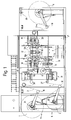
- Fig. 1 shows an embodiment of the device according to the invention in side view
- Fig. 2 shows a plan view of the device shown in Fig. 1.
- the device consists of two processing stations 5, 6, which are coordinated with one another in such a way that web sections 7 of a certain length of a second material web 4 are inserted into a first material web 3 at predetermined intervals.
- the insertion of the web sections 7 takes place intermittently and is controlled by a control device 9.
- the control is preferably a CNC-2 control.
- the individual elements of the processing stations 3, 4 are moved either by motor or pneumatically.
- the first material web 3 consists of a laminate that contains magnetic securing elements 29; in the second material web 4 there is no magnetic metal coating, rather it is preferably composed of two polypropylene layers glued together.
- the first material web 3 is unwound in the first, upper processing station 5 from a supply roll 1 corresponding to a desired length.
- the speed of the web feed and the desired length of the web section 7 of the first material web 3 are determined by means of a rotation angle sensor 22 which e.g. is attached to the axis of a measuring wheel placed on the unwound material web 3.
- the web tension during the unwinding process, the stopping and the continuation of the material web 3 is kept constant via dancer rollers 16.
- the lateral web run is monitored by web edge sensors and corrected to the desired edge position by means of a web edge controller 31.
- a so-called rotating frame control is used for web edge control 31. These are two rollers mounted side by side, which are arranged in a swiveling frame.
- the web feed is stopped in the first processing station 5.
- the material web 3 is clamped between the two clamping jaws of the two clamping devices 10a, 10b of the first processing station 5.
- This state of affairs is shown graphically in FIG. 3a and is referred to there as position I.1.
- the material web 3 between the two clamping devices 10a. 10b cut by means of a cutting device 12 moved into the plane of the web. The cut is made in such a way that the web ends have a certain projection with respect to the clamping devices 10a, 10b.
- one of the two clamping devices 10b is displaced in the running direction of the first material web 3 and the other clamping device 10a is moved against the running direction of the first material web 3 and positioned in predetermined positions.
- the position reached Clamping devices 10a, 10b is designated as position I.2 in FIG. 3a.
- a desired length of a web section 7 of the second material web 4 is unwound from a supply roll 2 in the second processing station 6.
- the web tension is kept constant in the processing station 6 via a dancer roller 16.
- the beginning of the material web 4 is passed between the clamping jaws of two clamping devices 11a, 11b positioned next to one another, which is shown in the drawing as position II.1 in FIG. 3b.
- air is directed against the material web from both sides during the web advance.
- air nozzles are provided in the clamping jaws of the first clamping device 11a.
- the clamping jaws of the second clamping device 11b are also bevelled on the side facing the web beginning of the material web 4.
- the outer clamping device 11b positioned in the running direction of the material web 4 clamps the material web 4 between the clamping jaws as soon as it has reached a certain protrusion. Then the outer clamping device 11b is moved a certain distance in the running direction of the material web 4. The desired length of the web section 7 of the second material web 4 is then unwound from the supply roll 2 of the second processing station 6. As soon as this has happened, the material web 4 is clamped between two clamping devices 13, 11a positioned counter to the web running direction and cut in the intermediate area between the two clamping devices 13, 11a by means of a cutting device 14. The The position of the clamping devices 13, 11a, 11b is marked as position II.2 in FIG. 3b.
- the cutting device 14 of the second processing station 6 is rigidly mounted.
- the cut is made in such a way that a certain protrusion of the cut web section 7 is achieved.
- Both clamping devices 11a, 11b are now moved into the plane of the material web 3 of the first processing station 5 in their reached positions. After this process has ended, the two clamping devices 11a, 11b of the second processing station 6 are positioned in the immediate vicinity of the two clamping devices 10a, 10b of the first processing station 3. This can be seen in the drawing in FIG. 3c and marked there as position III.
- the protrusions of the web ends of the first and second material webs 3, 4 preferably abut one another.
- the ends are fastened by means of two adhesive devices 17, 18; 19, 20 glued together.
- the clamping jaws of the clamping devices 10a, 10b, 11a, 11b are opened, and the material web 3 of the first processing station 5 is moved further with the inserted web section 7 of the second material web 4 and wound up on the winding roll 8.
- the next cycle follows.
- the adhesive devices 17, 18, 19, 20 are configured as follows: the dispensers for the adhesive tape are positioned on the side of the first material web 3, specifically in the vicinity of the positions of the clamping devices 10a, 10b of the first processing station 5, which are during the insertion of the web section 7 of the second material web 4.
- the end of the adhesive tape is gripped by the clamping jaws of a further clamping device arranged on a carriage and transversely to the running direction of the material web 3 pulled over the joints of the two material webs 3, 4.
- the adhesive tapes are cut with the help of knives.
- the sections of the adhesive tapes are held by means of vacuum suction cups.
- the clamping jaws which are in contact with the adhesive side of the adhesive tape, are coated with sandpaper, which enables detachment from the clamping jaws and subsequent application and gluing of the web ends of the web sections of the first and second material web 3, 4.
- the adhesive tapes are applied to the desired adhesive locations as follows: The vacuum suction cups bring the adhesive tapes into the desired positions above and below the abutting ends of the two material webs 3, 4. The adhesive tapes are pressed onto the two abutting web ends of the first and the second material web 3, 4.
- clamping devices 11a, 11b moved from the first processing station 5 into the second processing station 6 are moved back to their starting position in the second processing station 6; the second clamping device 11b of the second processing station 6 is then positioned again in the immediate vicinity of the first clamping device 11a of the second processing station 6.
- the cutting devices 12, 14 preferably perform a stamp-die cut, the punch being at an angle to the die as in the case of scissors. This design has the advantage that the knives are less quickly soiled by the adhesive that is located between the laminated material webs 3, 4.
- the end of the material web 3 on the supply roll 1 of the first processing station 5 is determined by means of a metal detector 24.
- the end of the material web 4 in the second processing station 6 is determined by means of a reflection detector 25.
- an ultrasonic sensor 26 is provided on the winding roll 8. If necessary, the latter sends a signal to the control device 9 and the machine is stopped.
- the control device 9 shows a flowchart for controlling the control device 9.
- the control device 9 is given the desired length LSOLL of the material web 3 and the desired length ISOLL of the web section 7 of the material web 4.
- the clamping devices 10a, 10b of the processing station 5 are moved to position I.1 under point 41.
- the material web 3 is advanced until the length LIST of the material web 3 corresponds to the predetermined length LSOLL.
- LSOLL the feed is stopped under point 44.
- the clamping devices 10a, 10b are then closed and the material web 3 is cut. Under program item 45, the clamping devices 10a, 10b are moved into position I.2.
- the clamping devices 11a, 11b are moved into position II.1; the clamping devices 11a, 11b are then brought into position II.2 under point 51.
- the material web 4 is moved forward until the length lIST of the web section 7 corresponds to the predetermined length lSOLL.
- the path feed is stopped and the clamping devices 11a, 11b are brought into position II.2 in accordance with program point 55.
- the clamping devices 11a, 11b of the processing station 6 are then moved into position III at 56.
- the adhesive devices 17, 18, 19, 20 are activated under point 57.
- the preliminary run in the processing station 5 is started. Of the At point 58 the program jumps back to the start and the next cycle is started.
Landscapes
- Replacement Of Web Rolls (AREA)
- Tyre Moulding (AREA)
- Unwinding Webs (AREA)
Applications Claiming Priority (2)
| Application Number | Priority Date | Filing Date | Title |
|---|---|---|---|
| DE19609180A DE19609180A1 (de) | 1996-03-09 | 1996-03-09 | Verfahren und Vorrichtung zum intermittierenden Einfügen von Bahnabschnitten einer zweiten Materialbahn in eine erste Materialbahn |
| DE19609180 | 1996-03-09 |
Publications (3)
| Publication Number | Publication Date |
|---|---|
| EP0794143A2 true EP0794143A2 (fr) | 1997-09-10 |
| EP0794143A3 EP0794143A3 (fr) | 1998-02-04 |
| EP0794143B1 EP0794143B1 (fr) | 2001-06-27 |
Family
ID=7787728
Family Applications (1)
| Application Number | Title | Priority Date | Filing Date |
|---|---|---|---|
| EP97103006A Expired - Lifetime EP0794143B1 (fr) | 1996-03-09 | 1997-02-25 | Procédé et dispositif d'insertion intermittente de segments de bande d'une seconde bande de matière dans une première bande de matière |
Country Status (3)
| Country | Link |
|---|---|
| EP (1) | EP0794143B1 (fr) |
| DE (2) | DE19609180A1 (fr) |
| ES (1) | ES2159062T3 (fr) |
Cited By (1)
| Publication number | Priority date | Publication date | Assignee | Title |
|---|---|---|---|---|
| CN112758733A (zh) * | 2021-04-09 | 2021-05-07 | 江苏长江智能制造研究院有限责任公司 | 棉花膜ab贴胶带拼接设备及ab贴胶带制作方法 |
Families Citing this family (2)
| Publication number | Priority date | Publication date | Assignee | Title |
|---|---|---|---|---|
| DE19850038A1 (de) * | 1998-10-30 | 2000-05-04 | Meto International Gmbh | Vorrichtung und Verfahren zum Einfügen eines Sicherungs- und/oder Identifizierungselements zwischen zwei Schichten eines Markierungsstreifens für Gepäckstücke |
| DE10144266C1 (de) * | 2001-09-08 | 2003-04-03 | Bosch Gmbh Robert | Vorrichtung zur Seitenaufprallerkennung in einem Fahrzeug |
Family Cites Families (5)
| Publication number | Priority date | Publication date | Assignee | Title |
|---|---|---|---|---|
| GB1387622A (en) * | 1971-04-15 | 1975-03-19 | Kodak Ltd | Spooling machines |
| DE2719597A1 (de) * | 1977-05-02 | 1978-11-16 | Zweckform Werk | Verfahren zum verbinden von etiketten tragenden traegerbaendern |
| ES2040343T3 (es) * | 1987-06-08 | 1993-10-16 | Esselte Meto International Gmbh | Dispositivos magneticos. |
| DE4239846C2 (de) * | 1992-11-27 | 2000-06-29 | Meto International Gmbh | Verfahren und Vorrichtung zur Herstellung von Diebstahlsicherungsetiketten |
| DE4416444C2 (de) * | 1994-05-10 | 2003-06-26 | Meto International Gmbh | Sicherheitsetikettenstreifen |
-
1996
- 1996-03-09 DE DE19609180A patent/DE19609180A1/de not_active Withdrawn
-
1997
- 1997-02-25 DE DE59703881T patent/DE59703881D1/de not_active Expired - Lifetime
- 1997-02-25 ES ES97103006T patent/ES2159062T3/es not_active Expired - Lifetime
- 1997-02-25 EP EP97103006A patent/EP0794143B1/fr not_active Expired - Lifetime
Cited By (1)
| Publication number | Priority date | Publication date | Assignee | Title |
|---|---|---|---|---|
| CN112758733A (zh) * | 2021-04-09 | 2021-05-07 | 江苏长江智能制造研究院有限责任公司 | 棉花膜ab贴胶带拼接设备及ab贴胶带制作方法 |
Also Published As
| Publication number | Publication date |
|---|---|
| DE19609180A1 (de) | 1997-09-11 |
| EP0794143B1 (fr) | 2001-06-27 |
| ES2159062T3 (es) | 2001-09-16 |
| DE59703881D1 (de) | 2001-08-02 |
| EP0794143A3 (fr) | 1998-02-04 |
Similar Documents
| Publication | Publication Date | Title |
|---|---|---|
| DE69525271T2 (de) | Etikettiermaterial | |
| DE60131885T2 (de) | Vorschubsystem für bahnförmiges material und vorrichtung zum auftragen von bahnförmigem material | |
| DE68908002T2 (de) | Verfahren und Vorrichtung zum Herstellen von Etiketten. | |
| DE3587719T2 (de) | Kaschiervorrichtung mit Ausdehnungsüberwachung. | |
| DE69311064T2 (de) | Vorrichtung zum Spleissen von Plastik-Schrumpffolie in einer Maschine zur Verarbeitung derartiger Folie | |
| DE69320962T2 (de) | Vorrichtung und verfahren zum spleissen eines nachlaufenden bahnendes mittels klebeband | |
| DE4211216C2 (de) | Band mit doppelseitig klebenden Abschnitten und Verfahren zu dessen Herstellung | |
| EP0363348B1 (fr) | Installation de coupe pour découper des pièces découpées de matière à ruban, en particulier des feuilles préimprégnées | |
| DE20310696U1 (de) | Bandaufbringvorrichtung zum Aufbringen von Band auf eine Oberfläche | |
| DE19722327A1 (de) | Verfahren zur Herstellung eines mehrlagigen Etiketts und Vorrichtung zur Durchführung des Verfahrens | |
| EP0360108B1 (fr) | Procédé et dispositif pour la distribution d'étiquettes | |
| DE4325944A1 (de) | Verfahren und Vorrichtung zum Verbinden von Materialbahnen, insbesondere aus Verpackungsmaterial | |
| DE3244430A1 (de) | Verfahren und vorrichtung zur herstellung eines sicherungsstreifens | |
| EP1922253B1 (fr) | Banderolage d'une pile d'objets | |
| DE2553611C3 (de) | Hellraum-FUmklebegerät | |
| EP0623451A1 (fr) | Procédé pour appliquer des bandes textiles caoutchoutées sur un tambour de confection de pneus et dispositif pour la mise en oeuvre de ce procédé | |
| EP0794143B1 (fr) | Procédé et dispositif d'insertion intermittente de segments de bande d'une seconde bande de matière dans une première bande de matière | |
| EP0997270B1 (fr) | Dispositif et procédé pour insérer un élément de sécurité et/ou d'identification entre deux couches d'un ruban d'identification pour bagages | |
| EP0756256B1 (fr) | Procédé et dispositif pour fabriquer des étiquettes de sécurité désactivables | |
| EP0162371B1 (fr) | Unité d'avance de feuilles pour une machine de fabrication de tubes | |
| DE3119109C2 (de) | Vorrichtung zum Wechseln von Vorratsrollen in einer Etikettiermaschine | |
| EP1312464B1 (fr) | Procédé pour la fabrication de bande d'étiquettes | |
| EP0683122A1 (fr) | Moyen adhésif pour raccorder des bandes de matériau embobinées en rouleaux entraînés | |
| DE4238145A1 (de) | Verfahren zur Herstellung von Sicherheitsetiketten | |
| WO2008031692A1 (fr) | Procédé et dispositif consistant à relier deux bandes de matériau |
Legal Events
| Date | Code | Title | Description |
|---|---|---|---|
| PUAI | Public reference made under article 153(3) epc to a published international application that has entered the european phase |
Free format text: ORIGINAL CODE: 0009012 |
|
| AK | Designated contracting states |
Kind code of ref document: A2 Designated state(s): BE DE ES FR GB IT NL SE |
|
| PUAL | Search report despatched |
Free format text: ORIGINAL CODE: 0009013 |
|
| AK | Designated contracting states |
Kind code of ref document: A3 Designated state(s): BE DE ES FR GB IT NL SE |
|
| 17P | Request for examination filed |
Effective date: 19980114 |
|
| RAP1 | Party data changed (applicant data changed or rights of an application transferred) |
Owner name: METO INTERNATIONAL GMBH |
|
| 17Q | First examination report despatched |
Effective date: 19990806 |
|
| GRAG | Despatch of communication of intention to grant |
Free format text: ORIGINAL CODE: EPIDOS AGRA |
|
| GRAG | Despatch of communication of intention to grant |
Free format text: ORIGINAL CODE: EPIDOS AGRA |
|
| GRAH | Despatch of communication of intention to grant a patent |
Free format text: ORIGINAL CODE: EPIDOS IGRA |
|
| GRAH | Despatch of communication of intention to grant a patent |
Free format text: ORIGINAL CODE: EPIDOS IGRA |
|
| GRAA | (expected) grant |
Free format text: ORIGINAL CODE: 0009210 |
|
| AK | Designated contracting states |
Kind code of ref document: B1 Designated state(s): BE DE ES FR GB IT NL SE |
|
| REF | Corresponds to: |
Ref document number: 59703881 Country of ref document: DE Date of ref document: 20010802 |
|
| ITF | It: translation for a ep patent filed | ||
| REG | Reference to a national code |
Ref country code: ES Ref legal event code: FG2A Ref document number: 2159062 Country of ref document: ES Kind code of ref document: T3 |
|
| GBT | Gb: translation of ep patent filed (gb section 77(6)(a)/1977) |
Effective date: 20010824 |
|
| ET | Fr: translation filed | ||
| REG | Reference to a national code |
Ref country code: GB Ref legal event code: IF02 |
|
| PLBE | No opposition filed within time limit |
Free format text: ORIGINAL CODE: 0009261 |
|
| STAA | Information on the status of an ep patent application or granted ep patent |
Free format text: STATUS: NO OPPOSITION FILED WITHIN TIME LIMIT |
|
| 26N | No opposition filed | ||
| PGFP | Annual fee paid to national office [announced via postgrant information from national office to epo] |
Ref country code: IT Payment date: 20060228 Year of fee payment: 10 |
|
| PGFP | Annual fee paid to national office [announced via postgrant information from national office to epo] |
Ref country code: NL Payment date: 20070222 Year of fee payment: 11 |
|
| PGFP | Annual fee paid to national office [announced via postgrant information from national office to epo] |
Ref country code: GB Payment date: 20070223 Year of fee payment: 11 |
|
| PGFP | Annual fee paid to national office [announced via postgrant information from national office to epo] |
Ref country code: ES Payment date: 20070226 Year of fee payment: 11 |
|
| PGFP | Annual fee paid to national office [announced via postgrant information from national office to epo] |
Ref country code: SE Payment date: 20070227 Year of fee payment: 11 |
|
| PGFP | Annual fee paid to national office [announced via postgrant information from national office to epo] |
Ref country code: BE Payment date: 20070327 Year of fee payment: 11 |
|
| PGFP | Annual fee paid to national office [announced via postgrant information from national office to epo] |
Ref country code: FR Payment date: 20070221 Year of fee payment: 11 |
|
| BERE | Be: lapsed |
Owner name: *METO INTERNATIONAL G.M.B.H. Effective date: 20080228 |
|
| EUG | Se: european patent has lapsed | ||
| GBPC | Gb: european patent ceased through non-payment of renewal fee |
Effective date: 20080225 |
|
| NLV4 | Nl: lapsed or anulled due to non-payment of the annual fee |
Effective date: 20080901 |
|
| PG25 | Lapsed in a contracting state [announced via postgrant information from national office to epo] |
Ref country code: NL Free format text: LAPSE BECAUSE OF NON-PAYMENT OF DUE FEES Effective date: 20080901 |
|
| REG | Reference to a national code |
Ref country code: FR Ref legal event code: ST Effective date: 20081031 |
|
| PG25 | Lapsed in a contracting state [announced via postgrant information from national office to epo] |
Ref country code: SE Free format text: LAPSE BECAUSE OF NON-PAYMENT OF DUE FEES Effective date: 20080226 |
|
| PG25 | Lapsed in a contracting state [announced via postgrant information from national office to epo] |
Ref country code: BE Free format text: LAPSE BECAUSE OF NON-PAYMENT OF DUE FEES Effective date: 20080228 |
|
| PG25 | Lapsed in a contracting state [announced via postgrant information from national office to epo] |
Ref country code: FR Free format text: LAPSE BECAUSE OF NON-PAYMENT OF DUE FEES Effective date: 20080229 |
|
| REG | Reference to a national code |
Ref country code: ES Ref legal event code: FD2A Effective date: 20080226 |
|
| PG25 | Lapsed in a contracting state [announced via postgrant information from national office to epo] |
Ref country code: GB Free format text: LAPSE BECAUSE OF NON-PAYMENT OF DUE FEES Effective date: 20080225 |
|
| PG25 | Lapsed in a contracting state [announced via postgrant information from national office to epo] |
Ref country code: ES Free format text: LAPSE BECAUSE OF NON-PAYMENT OF DUE FEES Effective date: 20080226 |
|
| PG25 | Lapsed in a contracting state [announced via postgrant information from national office to epo] |
Ref country code: IT Free format text: LAPSE BECAUSE OF NON-PAYMENT OF DUE FEES Effective date: 20070225 |
|
| PGFP | Annual fee paid to national office [announced via postgrant information from national office to epo] |
Ref country code: DE Payment date: 20120228 Year of fee payment: 16 |
|
| REG | Reference to a national code |
Ref country code: DE Ref legal event code: R082 Ref document number: 59703881 Country of ref document: DE |
|
| REG | Reference to a national code |
Ref country code: DE Ref legal event code: R119 Ref document number: 59703881 Country of ref document: DE Effective date: 20130903 |
|
| PG25 | Lapsed in a contracting state [announced via postgrant information from national office to epo] |
Ref country code: DE Free format text: LAPSE BECAUSE OF NON-PAYMENT OF DUE FEES Effective date: 20130903 |