EP0794149A2 - Aushängbare Verbindung zum Falten eines Wippauslegers - Google Patents
Aushängbare Verbindung zum Falten eines Wippauslegers Download PDFInfo
- Publication number
- EP0794149A2 EP0794149A2 EP97301399A EP97301399A EP0794149A2 EP 0794149 A2 EP0794149 A2 EP 0794149A2 EP 97301399 A EP97301399 A EP 97301399A EP 97301399 A EP97301399 A EP 97301399A EP 0794149 A2 EP0794149 A2 EP 0794149A2
- Authority
- EP
- European Patent Office
- Prior art keywords
- jib
- boom
- section
- luffing
- chords
- Prior art date
- Legal status (The legal status is an assumption and is not a legal conclusion. Google has not performed a legal analysis and makes no representation as to the accuracy of the status listed.)
- Granted
Links
Images


Classifications
-
- B—PERFORMING OPERATIONS; TRANSPORTING
- B66—HOISTING; LIFTING; HAULING
- B66C—CRANES; LOAD-ENGAGING ELEMENTS OR DEVICES FOR CRANES, CAPSTANS, WINCHES, OR TACKLES
- B66C23/00—Cranes comprising essentially a beam, boom, or triangular structure acting as a cantilever and mounted for translatory of swinging movements in vertical or horizontal planes or a combination of such movements, e.g. jib-cranes, derricks, tower cranes
- B66C23/62—Constructional features or details
- B66C23/82—Luffing gear
Definitions
- This invention relates to lift-crane booms and luffing jibs, and more particularly to an offsetting link that allows the luffing jib to be folded under and along the main boom, thereby decreasing the area necessary for assembly of the crane at the construction site.
- Construction cranes having large main booms are often equipped with a luffing jib to allow the crane to reach further from its base when the construction site is such that the swing axis of the main boom is confined, as for example, when neighboring structures obstruct the area through which the main boom can swing.
- a crane equipped with a luffing jib can raise its main boom at a steep angle relative to the ground surface, and then extend the luffing jib at a shallow angle relative to the ground surface, thereby increasing the crane's reach over such obstructions.
- the luffing jib may be well over half as long as the main boom, and in some instances may be nearly as long as the main boom. Consequently, a large area is needed at the construction site to lay the boom and luffing jib out during assembly, prior to raising the main boom. Given that the luffing jib design is intended to be used in confined construction sites, it is often impossible to lay out the entire combined length of the main boom and luffing jib. An alternative method of assembling the boom and luffing jib would be to fold the luffing jib under the main boom.
- the main boom has a much larger cross-sectional area than the luffing jib, and the luffing jib does not fold directly under the main boom when the luffing jib connection pivot, the point of attachment of the luffing jib to the main boom, is on or near the neutral axis of the main boom, because the luffing jib would then contact the main boom near the pivot point.
- Folding booms have been made with the pivot point moved laterally away from the neutral axis of the boom sections to allow the folding section to clear the main section, as in U.S. Patent Nos. 2,529,454 issued November 7, 1950 to Marcantonio, and 3,306,470, issued February 28, 1967 to Green, et al.
- Such an arrangement is not possible with a folding luffing jib, however, because the pivot would have to moved too far off the neutral axis to allow the luffing jib to clear the large main boom.
- this invention provides a crane boom and hinged luffing jib having a folded set-up configuration, comprising:
- the invention provides a crane boom and luffing jib assembly, comprising:
- a preferred embodiment of the offsetting link comprises a pair of side brackets connected by cross-braces to form a link of the same cross-sectional area as the jib sections to be joined, each side bracket comprising a pair of parallel plates spaced to receive an end of a jib section chord therebetween, the chords retained in the brackets by pins.
- a stop lug is positioned between the plates at the upper end of each bracket to engage an abutment member on the end of the upper members of one of the boom sections to limit the degree of offset allowable when the hinge pins are removed.
- the crane boom and luffing jib assembly includes a pin puller mechanism to remove the hinge pins, comprising:
- the crane boom and luffing jib are assembled by a method comprising the steps of:
- a crane comprises:
- This invention solves the problem of having the luffing jib connected to the boom near the boom longitudinal neutral axis while allowing the luffing jib to be configured in a folded set-up position, under the main boom.
- an offsetting link, or hinge within the luffing jib, the luffing jib is allowed to bend, clearing the main boom while keeping the pivot point close to the neutral axis of the boom sections.
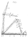
- FIG. 1 is a side view of a lift-crane equipped with a main boom and luffing jib in an "out front" layout position, prior to raising the boom.
- the dashed lines show the operation of raising the boom and luffing jib.
- FIG. 2 is a side view of a lift crane equipped with a main boom and luffing jib in the "folded-under" set-up configuration enabled by the present invention.
- FIG. 3 is an enlarged side view of the junction of the luffing jib butt section and jib boom section, connected by an offsetting link, in a coaxially-aligned orientation.
- FIG. 3A is a side view of the end of upper chord of the jib boom section showing the points of attachment to the offsetting link.
- FIG. 4 is a side view of the junction of the luffing jib butt section and jib boom section of FIG. 3, connected by the offsetting link in an offset orientation.
- FIG. 5 is a further enlarged side view of the offsetting link of FIG. 3.
- FIG. 6 is a plan view of the offsetting link taken along line 6-6 of FIG. 5.
- FIG. 7 is a top view of the offsetting link taken along line 7-7 of FIG. 5.
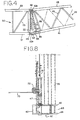
- FIG. 8 is a plan view of a pin puller mechanism for use with the offsetting link of FIG. 5.
- Fig. 1 depicts a lift crane 10 positioned prior to operational deployment in an "out front" layout position.
- the crane 10 has an upper works 12 pivotally mounted on a lower works 14 , the upper works 12 rotatable on the lower works 14 about a vertical swing axis, and a boom 16 to which is pivotally attached a luffing jib 18 at a jib connection pivot 17 , each of the boom 16 and luffing jib 18 having a longitudinal neutral axis 9 , 11 .
- Fig. 1 depicts a lift crane 10 positioned prior to operational deployment in an "out front" layout position.
- the crane 10 has an upper works 12 pivotally mounted on a lower works 14 , the upper works 12 rotatable on the lower works 14 about a vertical swing axis, and a boom 16 to which is pivotally attached a luffing jib 18 at a jib connection pivot 17 , each of the boom 16 and luffing jib 18 having
- the luffing jib 18 extends directly outwardly from the boom 16 , and each of the sections of the luffing jib 18 and boom 16 are coaxially aligned.
- the luffing jib 18 includes upper chords 22 , lower chords 24 and cross-braces 26 , and may be equipped with a wheel 19 at the outermost end.
- the terms "upper” and “lower” chords are chosen with reference to the ground surface 7 when the boom 16 is in a raised position and the luffing jib 18 is extended, as shown in the C position of Fig. 1, and this convention is followed herein.
- FIG. 1 depicts the raising operation from the "out front" configuration, indicated by position A, the operation is identical for raising the boom 16 and luffing jib 18 from the "folded-under” configuration.
- the boom 16 is raised by boom hoist rigging 13 , the outermost end of the jib top section 31 travels along the ground surface 7 , until the jib top section 31 is lifted off the ground surface 7 , after which the luffing jib 18 reaches a point at which is suspended nearly vertically from the boom 16 .
- First and second masts 23, 25 are connected to the boom 16 and luffing jib 18 respectively, and preferably, a luffing jib backstop assembly may also be included, as disclosed in U.S. Patent No. 5,292,016, the disclosure of which is incorporated herein by reference.
- At least one luffing jib pendant 20 originates on a take-up mechanism on or near the crane upper works 12 , traverses the masts 23, 25 and attaches near the outermost end of the luffing jib 18 . Tensioning the luffing jib pendant 20 causes the masts 23, 25 to be brought together, thereby raising the luffing jib 18 , as indicated by positions B, C and D of Fig. 1.
- Fig. 2 depicts the lift crane 10 positioned prior to operational deployment in a folded set-up position.
- the luffing jib 18 is folded under the boom 16 and rests on a ground surface 7 .
- the luffing jib 18 comprises a jib butt section 29 , a jib boom section 30 and jib top section 31 , having a wheel 19 attached to the outermost end.
- the jib butt section 29 is pivotally attached to the jib boom section 30 by an offsetting link 32 .
- Fig. 3 is a detailed side view of the connection between the jib butt section 29 and the jib boom section 30 , with the jib sections 29, 30 in a coaxially-aligned orientation. Although only one side surface of the structure is shown, it is to be understood that the opposite side of the structure is identical.
- the jib butt section 29 includes upper chords 41 , lower chords 43 and cross braces 45
- the jib boom section includes upper and lower chords 51 and 53 respectively, and cross braces 55 .
- An offsetting link 32 connects the jib butt section 29 to the jib boom section 30 .
- the lower chords 43 of the jib butt section 29 are connected to the lower chords 53 of the jib boom section 30 and the lower chords 43, 53 are connected to the offsetting link 32 by an axle pin 48 that extends through aligned holes in the lower end 32a of the offsetting link 32 and the lower chords 43, 53 of the jib sections 29, 30 .
- the upper chords 41 of the jib butt section 29 are connected to the upper end 32b of the offsetting link 32 by hinge pins 47 .
- the upper chords 51 of the jib boom section 30 are separately connected to the upper end 32b of the offsetting link 32 by pins 49 .
- the offsetting link 32 is not used when the crane is in the operational position, in that when the jib butt section 29 and jib boom section 30 are in the aligned configuration shown in Fig. 3, compression is transferred from the jib boom section 30 to the jib butt section 29 , not through the offsetting link 32 .
- Fig. 3A depicts the end of the upper chord 41 of the jib butt section 29 , illustrating the hole 69 aligned with hole 58 in the offsetting link 32 (shown in Fig. 5) to receive hinge pin 47 , a notch 63 to contact pin 49 when the jib butt section 29 and jib boom section 30 are in a coaxially-aligned orientation, and an abutment member 62 .
- Fig. 4 depicts the connection between the jib butt section 29 and the jib boom section 30 with the jib sections 29, 30 in an axially-offset position.
- hinge pin 47 When hinge pin 47 is removed, the jib sections 29, 30 are allowed to pivot on axle pin 48 until a stop lug 60 on the offsetting link 32 contacts an abutment member 62 (FIG. 3A) on the end of the upper chords 41 of the jib butt section 29 .
- Pin 49 remains in place to secure the upper chords 51 of the jib boom section 30 to the offsetting link 32 .
- Fig. 5 depicts the offsetting link 32 in a plane parallel to the longitudinal neutral axis of the jib
- Fig. 6 depicts the offsetting link 32 in a plane perpendicular to the longitudinal neutral axis of the jib
- Fig. 7 is a top view of the offsetting link.
- the offsetting link 32 includes side brackets 65 , comprising side plates 66, 67 , spaced to form a channel to receive the ends of the boom sections 29, 30 , and joined by a stop lug 60 .
- the lower ends 65a of the side brackets 65 each have a hole 61 to receive axle pin 48 .
- the upper ends 65b of the side brackets 65 each have two holes 58, 59 to receive hinge pins 47 and pins 49 respectively.
- the side brackets 65 are joined by cross braces 68 .
- Fig. 8 depicts a pin puller mechanism to allow the crane operator to remove hinge pins 47 while the boom and luffing jib are raised off the ground.
- a hand winch (not shown) carries a cable 70 , which passes over a pulley mechanism 72 , located between hinge pins 47 .
- Cable 70 is directed to both hinge pins 47 and attached to each by means of a ring eye 74 mounted on the head thereof, or by other suitable means. Winding the cable 70 onto the winch causes the hinge pins 47 to be simultaneously retracted
- the crane boom and luffing jib are raised to an operational position as follows, in reference to Figs. 1-5. With hinge pins 47 retracted, the top of boom 16 is raised upwardly by the boom hoist rigging 13 .
- the luffing jib 18 travels outwardly from the crane 10 , rolling along the ground on the wheel 19 attached to the end of the luffing jib 18 , until the luffing jib 18 is approximately vertical.
- the luffing jib 18 is approximately vertical, hanging from the boom 16 its own weight pulls the jib butt section 29 and jib boom section 30 into coaxial alignment, and the hinge pins 47 are replaced.
Landscapes
- Engineering & Computer Science (AREA)
- Mechanical Engineering (AREA)
- Jib Cranes (AREA)
Applications Claiming Priority (2)
| Application Number | Priority Date | Filing Date | Title |
|---|---|---|---|
| US60905996A | 1996-03-04 | 1996-03-04 | |
| US609059 | 1996-03-04 |
Publications (3)
| Publication Number | Publication Date |
|---|---|
| EP0794149A2 true EP0794149A2 (de) | 1997-09-10 |
| EP0794149A3 EP0794149A3 (de) | 1998-10-14 |
| EP0794149B1 EP0794149B1 (de) | 2004-02-25 |
Family
ID=24439193
Family Applications (1)
| Application Number | Title | Priority Date | Filing Date |
|---|---|---|---|
| EP97301399A Expired - Lifetime EP0794149B1 (de) | 1996-03-04 | 1997-03-03 | Aushängbare Verbindung zum Falten eines Wippauslegers |
Country Status (5)
| Country | Link |
|---|---|
| US (1) | US5842587A (de) |
| EP (1) | EP0794149B1 (de) |
| JP (1) | JPH107388A (de) |
| CA (1) | CA2198953C (de) |
| DE (1) | DE69727719T2 (de) |
Cited By (2)
| Publication number | Priority date | Publication date | Assignee | Title |
|---|---|---|---|---|
| WO2004087557A1 (en) * | 2003-04-02 | 2004-10-14 | Terex-Demag Gmbh & Co. Kg | Two-piece main boom for a latice-boom crane and method for erection thereof |
| CN101423179B (zh) * | 2007-10-29 | 2012-01-11 | 利勃海尔爱茵根有限公司 | 用于竖立起重机吊臂的方法 |
Families Citing this family (12)
| Publication number | Priority date | Publication date | Assignee | Title |
|---|---|---|---|---|
| FR2853891B1 (fr) * | 2003-04-17 | 2006-05-19 | Potain Sa | Dispositif d'assemblage demontable des elements de fleche d'une grue a tour |
| DE102008020767A1 (de) * | 2007-09-11 | 2009-04-02 | Terex-Demag Gmbh | Hilfseinrichtung zum Aufstellen der unteren und oberen Wippstütze eines verstellbaren Hilfsauslegers eines Mobilkranes |
| DE102009022262A1 (de) * | 2009-05-22 | 2010-11-25 | Terex Demag Gmbh | Winkelverstellung eines Auslegersystems |
| US9206021B2 (en) | 2012-09-26 | 2015-12-08 | Kobelco Cranes Co., Ltd. | Crane and crane assembling method |
| DE102015119379B3 (de) * | 2015-11-10 | 2017-03-30 | Terex Global Gmbh | Mobilkran und Verfahren zum Abwinkeln einer Hauptauslegerverlängerung relativ zu einem Hauptausleger eines Mobilkrans |
| DE102015119381B3 (de) * | 2015-11-10 | 2017-04-27 | Terex Global Gmbh | Mobilkran und Verfahren zum Abwinkeln einer Hauptauslegerverlängerung relativ zu einem Hauptausleger eines Mobilkrans |
| DE102015120350B3 (de) * | 2015-11-24 | 2017-05-24 | Terex Global Gmbh | Mobilkran zum Abwinkeln einer Hauptauslegerverlängerung relativ zu einem Hauptausleger eines Mobilkrans |
| US10065841B2 (en) | 2016-01-26 | 2018-09-04 | Altec Industries, Inc. | Compact stowable luffing jib for a crane |
| JP6834789B2 (ja) * | 2017-06-05 | 2021-02-24 | コベルコ建機株式会社 | ストラットの引き起こし方法、およびクレーン |
| NL2019511B1 (en) * | 2017-09-08 | 2019-03-19 | Mammoet Eng B V | Crane comprising first mast with tiltable first mast upper part |
| DE102018114832A1 (de) * | 2018-06-20 | 2019-12-24 | Liebherr-Werk Ehingen Gmbh | Großkran mit Ausleger |
| CN109264582A (zh) * | 2018-12-05 | 2019-01-25 | 中联重科股份有限公司 | 起重机的起重臂控制方法、装置及起重机 |
Family Cites Families (20)
| Publication number | Priority date | Publication date | Assignee | Title |
|---|---|---|---|---|
| US1929416A (en) * | 1930-09-11 | 1933-10-10 | Bucyrus Erie Co | Creeping traction |
| US2529454A (en) * | 1948-01-10 | 1950-11-07 | Eugene P Reading Inc | Foldable boom |
| US3085695A (en) * | 1961-03-23 | 1963-04-16 | Carl A Miller | Hinge for crane boom |
| AT245204B (de) * | 1961-03-27 | 1966-02-25 | Roger Benoit Cadillon | Fahrbarer Schleppkran |
| US3306470A (en) * | 1965-01-25 | 1967-02-28 | Robert A Green | Folding boom for mobile cranes |
| US3323660A (en) * | 1965-09-21 | 1967-06-06 | Northwest Engineering Corp | Lattice boom construction |
| US3557969A (en) * | 1967-04-06 | 1971-01-26 | Coles Krane Gmbh | Outrigger mast for crane |
| US3831771A (en) * | 1973-02-16 | 1974-08-27 | Harnischfeger Corp | Mobile crane with telescopic boom and jib and method for connecting the latter |
| US4106631A (en) * | 1977-02-18 | 1978-08-15 | J. I. Case Company | Fly and jib assembly for crane |
| FR2409225A1 (fr) * | 1977-11-21 | 1979-06-15 | Creusot Loire | Perfectionnement aux grues telescopiques |
| US4383616A (en) * | 1980-12-24 | 1983-05-17 | Kidde, Inc. | Luffing jib for construction crane |
| US4491229A (en) * | 1981-02-25 | 1985-01-01 | Fmc Corporation | Boom extension stowage system |
| US4484686A (en) * | 1982-04-23 | 1984-11-27 | Kidde, Inc. | Multiple offset boom extension |
| US4653655A (en) * | 1985-12-23 | 1987-03-31 | Harnischfeger Corporation | Crane boom having variable angle offset capability |
| JPS6327396A (ja) * | 1986-07-21 | 1988-02-05 | 株式会社タダノ | 伸縮ブ−ムに継ぎ足されるジブ |
| DE3842726C3 (de) * | 1988-12-19 | 2001-01-18 | Mannesmann Ag | Mehrschnittige Bolzenverbindung |
| US5199586A (en) * | 1991-07-25 | 1993-04-06 | The Manitowoc Company, Inc. | Quick-connect sectional boom members for cranes and the like |
| US5111945A (en) * | 1991-09-13 | 1992-05-12 | Kidde Industries, Inc. | Boom extension alignment device |
| FR2682097A1 (fr) * | 1991-10-02 | 1993-04-09 | Potain Sa | Fleche a repliage automatise pour grue. |
| US5292016A (en) * | 1992-10-08 | 1994-03-08 | The Manitowoc Company | Luffing jib backstop assembly |
-
1997
- 1997-03-03 DE DE1997627719 patent/DE69727719T2/de not_active Expired - Fee Related
- 1997-03-03 EP EP97301399A patent/EP0794149B1/de not_active Expired - Lifetime
- 1997-03-03 CA CA002198953A patent/CA2198953C/en not_active Expired - Fee Related
- 1997-03-04 JP JP9049359A patent/JPH107388A/ja active Pending
- 1997-08-19 US US08/916,738 patent/US5842587A/en not_active Expired - Lifetime
Cited By (3)
| Publication number | Priority date | Publication date | Assignee | Title |
|---|---|---|---|---|
| WO2004087557A1 (en) * | 2003-04-02 | 2004-10-14 | Terex-Demag Gmbh & Co. Kg | Two-piece main boom for a latice-boom crane and method for erection thereof |
| US7270243B2 (en) | 2003-04-02 | 2007-09-18 | Terex-Demag Gmbh & Co. Kg | Method for erecting an at least two-piece main boom for a lattice-boom crane and lattice-boom crane built accordingly |
| CN101423179B (zh) * | 2007-10-29 | 2012-01-11 | 利勃海尔爱茵根有限公司 | 用于竖立起重机吊臂的方法 |
Also Published As
| Publication number | Publication date |
|---|---|
| DE69727719D1 (de) | 2004-04-01 |
| JPH107388A (ja) | 1998-01-13 |
| DE69727719T2 (de) | 2005-01-13 |
| EP0794149B1 (de) | 2004-02-25 |
| CA2198953C (en) | 2000-10-10 |
| CA2198953A1 (en) | 1997-09-04 |
| EP0794149A3 (de) | 1998-10-14 |
| US5842587A (en) | 1998-12-01 |
Similar Documents
| Publication | Publication Date | Title |
|---|---|---|
| EP0794149B1 (de) | Aushängbare Verbindung zum Falten eines Wippauslegers | |
| US8839966B2 (en) | Folding jib main strut and transportable reeved strut caps | |
| US4461369A (en) | Articulated boom and assembly therefor | |
| US20100294735A1 (en) | Crane Backstay Spreader | |
| RU2200699C2 (ru) | Способ и устройство для монтажа растяжек грузоподъемной стрелы башенного подъемного крана | |
| RU2256599C2 (ru) | Устройство для раскрытия или складывания головных элементов стрелы крана | |
| JP2019069838A (ja) | クレーン、ジブ組立て方法 | |
| JP2002507530A (ja) | リングリフトクレーン | |
| JP3566418B2 (ja) | ラフィングジブ付き移動式クレーン | |
| US20040124167A1 (en) | Mobile crane with elongated boom | |
| JP5717419B2 (ja) | 移動式クレーンおよび移動式クレーンの組立方法 | |
| JP7773323B2 (ja) | 伸縮ブーム用の高速組立ヘッド及びそれを組み立てる方法 | |
| US4050586A (en) | Apparatus for raising & lowering a mast and boom on a mobile crane | |
| EP0941958A1 (de) | System zur Verkleinerung der äusseren Abmessungen des Auslegers eines zusammenklappbaren Krans | |
| JPH0761773A (ja) | ジブクレーン | |
| JP2008114978A (ja) | 移動式タワークレーン | |
| US3933250A (en) | Guy crane jib tip prop | |
| US7380677B2 (en) | Crane, as well as a process for raising its boom | |
| JP4177913B2 (ja) | ラフィングジブ付き移動式クレーン | |
| JP4777821B2 (ja) | タワークレーン | |
| JPH0948589A (ja) | タワークレーンのスイングレバー | |
| JP2001302181A (ja) | 移動式クレーンのジブ張出格納装置 | |
| JP7146032B2 (ja) | 分離可能なaフレームを備える移動式クレーン | |
| JPH0324556Y2 (de) | ||
| EP4534468A1 (de) | Kran und kranmontageverfahren |
Legal Events
| Date | Code | Title | Description |
|---|---|---|---|
| PUAI | Public reference made under article 153(3) epc to a published international application that has entered the european phase |
Free format text: ORIGINAL CODE: 0009012 |
|
| AK | Designated contracting states |
Kind code of ref document: A2 Designated state(s): DE FR GB NL |
|
| PUAL | Search report despatched |
Free format text: ORIGINAL CODE: 0009013 |
|
| AK | Designated contracting states |
Kind code of ref document: A3 Designated state(s): DE FR GB NL |
|
| 17P | Request for examination filed |
Effective date: 19990211 |
|
| 17Q | First examination report despatched |
Effective date: 20011106 |
|
| RAP1 | Party data changed (applicant data changed or rights of an application transferred) |
Owner name: MANITOWOC CRANE COMPANIES, INC. |
|
| GRAH | Despatch of communication of intention to grant a patent |
Free format text: ORIGINAL CODE: EPIDOS IGRA |
|
| GRAS | Grant fee paid |
Free format text: ORIGINAL CODE: EPIDOSNIGR3 |
|
| GRAA | (expected) grant |
Free format text: ORIGINAL CODE: 0009210 |
|
| AK | Designated contracting states |
Kind code of ref document: B1 Designated state(s): DE FR GB NL |
|
| REG | Reference to a national code |
Ref country code: GB Ref legal event code: FG4D |
|
| REF | Corresponds to: |
Ref document number: 69727719 Country of ref document: DE Date of ref document: 20040401 Kind code of ref document: P |
|
| ET | Fr: translation filed | ||
| PLBE | No opposition filed within time limit |
Free format text: ORIGINAL CODE: 0009261 |
|
| STAA | Information on the status of an ep patent application or granted ep patent |
Free format text: STATUS: NO OPPOSITION FILED WITHIN TIME LIMIT |
|
| 26N | No opposition filed |
Effective date: 20041126 |
|
| PGFP | Annual fee paid to national office [announced via postgrant information from national office to epo] |
Ref country code: NL Payment date: 20090310 Year of fee payment: 13 |
|
| PGFP | Annual fee paid to national office [announced via postgrant information from national office to epo] |
Ref country code: GB Payment date: 20090206 Year of fee payment: 13 |
|
| PGFP | Annual fee paid to national office [announced via postgrant information from national office to epo] |
Ref country code: DE Payment date: 20090331 Year of fee payment: 13 |
|
| PGFP | Annual fee paid to national office [announced via postgrant information from national office to epo] |
Ref country code: FR Payment date: 20090306 Year of fee payment: 13 |
|
| REG | Reference to a national code |
Ref country code: NL Ref legal event code: V1 Effective date: 20101001 |
|
| GBPC | Gb: european patent ceased through non-payment of renewal fee |
Effective date: 20100303 |
|
| REG | Reference to a national code |
Ref country code: FR Ref legal event code: ST Effective date: 20101130 |
|
| PG25 | Lapsed in a contracting state [announced via postgrant information from national office to epo] |
Ref country code: NL Free format text: LAPSE BECAUSE OF NON-PAYMENT OF DUE FEES Effective date: 20101001 Ref country code: FR Free format text: LAPSE BECAUSE OF NON-PAYMENT OF DUE FEES Effective date: 20100331 |
|
| PG25 | Lapsed in a contracting state [announced via postgrant information from national office to epo] |
Ref country code: DE Free format text: LAPSE BECAUSE OF NON-PAYMENT OF DUE FEES Effective date: 20101001 |
|
| PG25 | Lapsed in a contracting state [announced via postgrant information from national office to epo] |
Ref country code: GB Free format text: LAPSE BECAUSE OF NON-PAYMENT OF DUE FEES Effective date: 20100303 |