EP0794264A1 - Gasturbinenbläserschaufeln mit Laserschock behandelte Kanten - Google Patents
Gasturbinenbläserschaufeln mit Laserschock behandelte Kanten Download PDFInfo
- Publication number
- EP0794264A1 EP0794264A1 EP96301460A EP96301460A EP0794264A1 EP 0794264 A1 EP0794264 A1 EP 0794264A1 EP 96301460 A EP96301460 A EP 96301460A EP 96301460 A EP96301460 A EP 96301460A EP 0794264 A1 EP0794264 A1 EP 0794264A1
- Authority
- EP
- European Patent Office
- Prior art keywords
- laser shock
- airfoil
- shock peened
- fan blade
- extending
- Prior art date
- Legal status (The legal status is an assumption and is not a legal conclusion. Google has not performed a legal analysis and makes no representation as to the accuracy of the status listed.)
- Granted
Links
- 230000035939 shock Effects 0.000 title claims abstract description 101
- 238000010304 firing Methods 0.000 description 9
- 238000000034 method Methods 0.000 description 7
- 239000003973 paint Substances 0.000 description 6
- 239000000463 material Substances 0.000 description 5
- 238000002485 combustion reaction Methods 0.000 description 3
- XLYOFNOQVPJJNP-UHFFFAOYSA-N water Substances O XLYOFNOQVPJJNP-UHFFFAOYSA-N 0.000 description 3
- 238000010276 construction Methods 0.000 description 2
- 230000000694 effects Effects 0.000 description 2
- 238000010422 painting Methods 0.000 description 2
- 230000002411 adverse Effects 0.000 description 1
- 230000004075 alteration Effects 0.000 description 1
- 238000005452 bending Methods 0.000 description 1
- 230000005284 excitation Effects 0.000 description 1
- 239000000446 fuel Substances 0.000 description 1
- 230000002045 lasting effect Effects 0.000 description 1
- 239000010410 layer Substances 0.000 description 1
- 229910001092 metal group alloy Inorganic materials 0.000 description 1
- 238000012986 modification Methods 0.000 description 1
- 230000004048 modification Effects 0.000 description 1
- 230000005855 radiation Effects 0.000 description 1
- 238000009419 refurbishment Methods 0.000 description 1
- 239000002344 surface layer Substances 0.000 description 1
Images

Classifications
-
- F—MECHANICAL ENGINEERING; LIGHTING; HEATING; WEAPONS; BLASTING
- F01—MACHINES OR ENGINES IN GENERAL; ENGINE PLANTS IN GENERAL; STEAM ENGINES
- F01D—NON-POSITIVE DISPLACEMENT MACHINES OR ENGINES, e.g. STEAM TURBINES
- F01D5/00—Blades; Blade-carrying members; Heating, heat-insulating, cooling or antivibration means on the blades or the members
- F01D5/12—Blades
- F01D5/28—Selecting particular materials; Particular measures relating thereto; Measures against erosion or corrosion
- F01D5/286—Particular treatment of blades, e.g. to increase durability or resistance against corrosion or erosion
-
- C—CHEMISTRY; METALLURGY
- C21—METALLURGY OF IRON
- C21D—MODIFYING THE PHYSICAL STRUCTURE OF FERROUS METALS; GENERAL DEVICES FOR HEAT TREATMENT OF FERROUS OR NON-FERROUS METALS OR ALLOYS; MAKING METAL MALLEABLE, e.g. BY DECARBURISATION OR TEMPERING
- C21D10/00—Modifying the physical properties by methods other than heat treatment or deformation
- C21D10/005—Modifying the physical properties by methods other than heat treatment or deformation by laser shock processing
-
- Y—GENERAL TAGGING OF NEW TECHNOLOGICAL DEVELOPMENTS; GENERAL TAGGING OF CROSS-SECTIONAL TECHNOLOGIES SPANNING OVER SEVERAL SECTIONS OF THE IPC; TECHNICAL SUBJECTS COVERED BY FORMER USPC CROSS-REFERENCE ART COLLECTIONS [XRACs] AND DIGESTS
- Y02—TECHNOLOGIES OR APPLICATIONS FOR MITIGATION OR ADAPTATION AGAINST CLIMATE CHANGE
- Y02T—CLIMATE CHANGE MITIGATION TECHNOLOGIES RELATED TO TRANSPORTATION
- Y02T50/00—Aeronautics or air transport
- Y02T50/60—Efficient propulsion technologies, e.g. for aircraft
-
- Y—GENERAL TAGGING OF NEW TECHNOLOGICAL DEVELOPMENTS; GENERAL TAGGING OF CROSS-SECTIONAL TECHNOLOGIES SPANNING OVER SEVERAL SECTIONS OF THE IPC; TECHNICAL SUBJECTS COVERED BY FORMER USPC CROSS-REFERENCE ART COLLECTIONS [XRACs] AND DIGESTS
- Y10—TECHNICAL SUBJECTS COVERED BY FORMER USPC
- Y10S—TECHNICAL SUBJECTS COVERED BY FORMER USPC CROSS-REFERENCE ART COLLECTIONS [XRACs] AND DIGESTS
- Y10S148/00—Metal treatment
- Y10S148/902—Metal treatment having portions of differing metallurgical properties or characteristics
- Y10S148/903—Directly treated with high energy electromagnetic waves or particles, e.g. laser, electron beam
Definitions
- This invention relates to gas turbine engine rotor blades and, more particularly, to leading edges having localized compressive residual stresses imparted by laser shock peening.
- Gas turbine engines and, in particular, aircraft gas turbine engines rotors operate at high rotational speeds that produce high tensile and vibratory stress fields within the blade and make the fan blades susceptible to foreign object damage (FOD). Vibrations may also be caused by vane wakes and inlet pressure distortions as well as other aerodynamic phenomena. This FOD causes nicks and tears and, hence, stress concentrations in leading and trailing edges of fan blade airfoils. These nicks and tears become the source of high stress concentrations or stress risers and severely limit the life of these blades due to High Cycle Fatigue (HCF) from vibratory stresses. FOD damage may also result in a loss of engine due to a release of a failed blade.
- FOD foreign object damage
- the present invention is directed towards this end and provides a fan blade with regions of deep compressive residual stresses imparted by laser shock peening leading and trailing edge surfaces of the fan blade.
- the region of deep compressive residual stresses imparted by laser shock peening of the present invention is not to be confused with a surface layer zone of a work piece that contains locally bounded compressive residual stresses that are induced by a hardening operation using a laser beam to locally heat and, thereby, harden the work piece such as that which is disclosed in U.S. Patent No. 5,235,838, entitled "Method and apparatus for truing or straightening out of true work pieces".
- the present invention uses multiple radiation pulses from high power pulsed lasers to produce shock waves on the surface of a work piece similar to methods disclosed in U.S. Patent No. 3,850,698, entitled "Altering Material Properties"; U.S. Patent No.
- Laser peening as understood in the art and as used herein means utilizing a laser beam from a laser beam source to produce a strong localized compressive force on a portion of a surface. Laser peening has been utilized to create a compressively stressed protection layer at the outer surface of a workpiece which is known to considerably increase the resistance of the workpiece to fatigue failure as disclosed in U.S. Patent No. 4,937,421, entitled “Laser Peening System and Method".
- the prior art does not disclose fan blade leading edges of the type claimed by the present patent nor the methods how to produce them. It is to this end that the present invention is directed.
- the present invention provides a gas turbine engine fan blade having at least one laser shock peened surface along the leading and/or trailing edges of the blade and a region of deep compressive residual stresses imparted by laser shock peening (LSP) extending from the laser shock peened surface into the blade.
- LSP laser shock peening
- the blade has laser shock peened surfaces on both suction and pressure sides of the blade wherein both sides were simultaneously laser shock peened.
- the present invention can be used for new or used and repaired fan blades.
- the improved ability to safely build gas turbine engine blades designed to operate in high tensile and vibratory stress fields which can better withstand fatigue failure due to nicks and tears in the leading and trailing edges of the fan blade and have an increased life over conventionally constructed fan blades.
- Another advantage of the present invention is that fan blades can be constructed with commercially acceptable life spans without increasing thicknesses along the leading and trailing edges, as is conventionally done, thus, avoiding unwanted weight on the blade.
- Another advantage of constructing fan blades without increasing thicknesses along the leading and trailing edges is improved aerodynamic performance of the airfoil that is available for blades with thinner leading and trailing edges.
- the present invention makes it possible to provide new and refurbished fan blades with enhanced capability and, in particular, extends the fan blade life in order to reduce the number of refurbishments and/or replacements of the blades.
- the present invention also allows aircraft engine, fan blades to be designed with adequate margins by increasing vibratory stress capabilities to account for FOD or other fan blade damage without beefing up the area along the leading edges which increase the weight of the fan blade and engine.
- the present invention can be advantageously used to refurbish existing fan blades in order to ensure safe and reliable operation of older gas turbine engine fan blades while avoiding expensive redesign efforts or frequent replacement of suspect fan blades as is now often done or required.
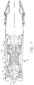
- FIG. 1 Illustrated in FIG. 1 is a schematic representation of an exemplary aircraft turbofan gas turbine engine 10 including a fan blade 8 in accordance with one embodiment of the present invention.
- the gas turbine engine 10 is circumferentially disposed about an engine centerline 11 and has, in serial flow relationship, a fan section 12, a high pressure compressor 16, a combustion section 18, a high pressure turbine 20, and a low pressure turbine 22.
- the combustion section 18, high pressure turbine 20, and low pressure turbine 22 are often referred to as the hot section of the engine 10.
- a high pressure rotor shaft 24 connects, in driving relationship, the high pressure turbine 20 to the high pressure compressor 16 and a low pressure rotor shaft 26 drivingly connects the low pressure turbine 22 to the fan section 12.
- Fuel is burned in the combustion section 18 producing a very hot gas flow 28 which is directed through the high pressure and low pressure turbines 20 and 22 respectively to power the engine 10.
- a portion of the air passing through the fan section 12 is bypassed around the high pressure compressor 16 and the hot section through a bypass duct 30 having an entrance or splitter 32 between the fan section 12 and the high pressure compressor 16.
- Many engines have a low pressure compressor (not shown) mounted on the low pressure rotor shaft 26 between the splitter 32 and the high pressure compressor 16.
- the fan section 12 is a multi-stage fan section, as are many gas turbine engines, illustrated by first, second, and third fan stages; 12a, 12b, and 12c respectively.
- the fan blade 8 of the present invention is designed to be used in a single stage fan section or in any stage of a multi-stage fan section.
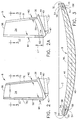
- the fan blade 8 includes an airfoil 34 extending radially outward from a blade platform 36 to a blade tip 38.
- the fan blade 8 includes a root section 40 extending radially inward from the platform 36 to a radially inward end 37 of the root section 40.
- a blade root 42 which is connected to the platform 36 by a blade shank 44.
- the airfoil 34 extends in the chordwise direction between a leading edge LE and a trailing edge TE of the airfoil.
- a chord C of the airfoil 34 is the line between the leading LE and trailing edge TE at each cross section of the blade as illustrated in FIG. 3.
- a pressure side 46 of the airfoil 34 faces in the general direction of rotation as indicated by the arrow and a suction side 48 is on the other side of the airfoil and a mean-line ML is generally disposed midway between the two faces in the chordwise direction.
- fan blade 8 has a leading edge section 50 that extends along the leading edge LE of the airfoil 34 from the blade platform 36 to the blade tip 38.
- the leading edge section 50 includes a predetermined first width W1 such that the leading edge section 50 encompasses nicks 52 and tears that may occur along the leading edge of the airfoil 34.
- the airfoil 34 subject to a significant tensile stress field due to centrifugal forces generated by the fan blade 8 rotating during engine operation.
- the airfoil 34 is also subject to vibrations generated during engine operation and the nicks 52 and tears operate as high cycle fatigue stress risers producing additional stress concentrations around them.
- At least one and preferably both of the pressure side 46 and the suction side 48 have at least one laser shock peened surface 54 and a pre-stressed region 56 having deep compressive residual stresses imparted by laser shock peening (LSP) extending into the airfoil 34 from the laser shock peened surface as seen in FIG. 3.
- LSP laser shock peening
- the airfoil has two laser shock peened surface 54 along the leading edge LE and the pre-stressed regions 56 are coextensive with the leading edge section 50 in the chordwise direction to the full extent of width W1 and are deep enough into the airfoil 34 to coalesce for at least a part of the width W1.
- the pre-stressed regions 56 are shown coextensive with the leading edge section 50 in the radial direction along the leading edge LE but may be shorter.
- the entire laser shock peened surfaces 54 is formed by overlapping laser shocked peened circular spots 58.
- FIG. 2A illustrates the invention for a partial leading edge length pre-stressed regions 56 extending over a laser shock peened surface length L1 of the leading edge LE that is generally centered about a predetermined nodal line 59 where it intercepts the leading edge LE.
- the nodal line 59 is one of a dominant failure modes due to vibratory stress. This stress may be due to excitations of the blade in bending and torsional flexure modes. The dominant failure mode may not always be the maximum stress mode but rather a lower stress mode or combination of modes that exist for longer durations over the engine's mission.
- the predetermined nodal line 59 illustrated in FIG. 2A is due to a first flex mode.
- a nick 52 located in this area of the leading edge LE has the greatest potential for failing the blade under resonance in this mode.
- the laser shock peened surface length L1 of the partial leading edge length pre-stressed regions 56 may extend along the leading edge LE about 20% of the fan blade length from the tip 38 to the platform 36.
- the present invention includes a fan blade construction with only the trailing edge TE having laser shock peened surfaces 54 on a trailing edge section 70 having a second width W2 and along the trailing edge TE.
- the associated pre-stressed regions 56 having deep compressive residual stresses imparted by laser shock peening (LSP) extends into the airfoil 34 from the laser shock peened surfaces 54 on the trailing edge section 70.
- At least one and preferably both of the pressure side 46 and the suction side 48 have a laser shock peened surfaces 54 and a pre-stressed region 56 having deep compressive residual stresses imparted by laser shock peening (LSP) extending into the airfoil 34 from the laser shock peened surfaces on a trailing edge section along the trailing edge TE.
- the compressive pre-stressed regions 56 are coextensive with the leading edge section 50 in the chordwise direction to the full extent of width W2 and are deep enough into the airfoil 34 to coalesce for at least a part of the width W2.
- the compressive pre-stressed regions 56 are shown coextensive with the leading edge section 50 in the radial direction along the trailing edge TE but may be shorter, extending from the tip 38 a portion of the way along the trailing edge TE towards the platform 36.
- the laser beam shock induced deep compressive residual stresses in the compressive pre-stressed regions 56 are generally about 50-150 KPSI (Kilo Pounds per Square Inch) extending from the laser shocked surfaces 54 to a depth of about 20-50 mils into laser shock induced compressive residually stressed regions 56.
- the laser beam shock induced deep compressive residual stresses are produced by repetitively firing a high energy laser beam that is defocused ⁇ a few mils with respect to the surface 54 which is covered with paint.
- the laser beam typically has a peak power density on the order of magnitude of a gigawatt/cm 2 and is fired through a curtain of flowing water that is flowed over the painted surface 54.
- the paint is ablated generating plasma which results in shock waves on the surface of the material.
- shock waves are re-directed towards the painted surface by the curtain of flowing water to generate travelling shock waves (pressure waves) in the material below the painted surface.
- the amplitude and quantity of these shockwave determine the depth and intensity of compressive stresses.
- the paint is used to protect the target surface and also to generate plasma. Ablated paint material is washed out by the curtain of flowing water.
- the laser may be fired sequentially "on the fly", as illustrated in FIG. 4, to hit a pattern of non adjacent centers X along a row centerline 62 of laser shocked peened circular spots 58 (indicated by the circles) having a diameter D in a row 64 of overlapping laser shock peened circular spots.
- the pattern may be of multiple overlapping rows 64 of overlapping shock peened circular spots on the laser shock peened surfaces 54.
- a first overlap is between adjacent laser shock peened circular spots 58 in a given row and is generally defined by a first offset O1 between centers X of the adjacent laser shock peened circular spots 58 and can vary from about 30%-50% or more of the diameter D.
- a second overlap is between adjacent laser shock peened circular spots 58 in adjacent rows and is generally defined by a second offset O2 between adjacent row centerlines 62 and can vary from about 30%-50% of the diameter D depending on applications and the strength or fluency of the laser beam.
- This method is designed so that only virgin or near virgin paint is ablated away without any appreciable effect or damage on the surface of the airfoil. This is to prevent even minor blemishes or remelt due to the laser which might otherwise cause unwanted aerodynamic effects on the blade's operation.
- Several sequences may be required to cover the entire pattern and repainting of the laser shock peened surfaces 54 is done between each sequence of laser firings.
- the laser firing each sequence has multiple laser firings or pulses with a period between firings that is often referred to a "rep". During the rep the part is moved so that the next pulse occurs at the location of the next laser shocked peened circular spot 58 in the sequence.
- the part is moved continuously and timed to be at the appropriate location at the pulse or firing of the laser beam.
- One or more repeats of each sequence may be used to hit each laser shocked peened circular spot 58 more than once. This may also allow for less laser power to be used in each firing or laser pulse.
- One example of the present invention is a fan blade 8 having an airfoil about 11 inches long, a chord C about 3.5 inches, and laser shock peened surfaces 54 about 2 inches long along the leading edge LE.
- the laser shock peened surfaces 54 are about .5 inches wide (W1).
- a first row 64 of laser shocked peened circular spots 58 nearest the leading edge LE extends past the leading edge by about 20% of the laser spot diameter D which is about .27" thus imparting deep compressive residual stresses in the pre-stressed region 56 below the laser shock peened surfaces 54 which extend about .54 inches from the leading edge.
- Four sequences of continuous laser firings and blade movement are used.
- the firings between reps of the laser are done on spots 58 which lie on unabated painted surfaces which requires a repaint between each of the sequences.
- Each spot 58 is hit three times and therefore three sets of four sequences are used for a total of twelve paint and repaints of the laser shock peened surface 54.
- An alternative to painting and repainting is to use no painting at all and form the above mentioned plasma with metal alloy on the surface of the airfoil. After the laser shock peening process is done the laser shock peened surface may be removed to a depth sufficient to remove the remelt that forms on the surface that might interfere with the airfoils operation.
- the present invention includes a fan blade 8 construction with either the leading edge LE or the trailing edge TE sections or both the leading edge LE and the trailing edge TE sections having laser shock peened surfaces 54 and associated pre-stressed regions 56 with deep compressive residual stresses imparted by laser shock peening (LSP) as disclosed above.
- LSP laser shock peening
- the laser shocked surface and associated pre-stressed region on the trailing edge TE section is constructed similarly to the leading edge LE section as described above.
- Nicks on the leading edge LE tend to be larger than nicks on the trailing edge TE and therefore the first width W1 of the leading edge section 50 may be greater than the second width W2 of the trailing edge section 70.
- W1 may be about .5 inches and W2 may be about .25 inches.
Landscapes
- Engineering & Computer Science (AREA)
- Chemical & Material Sciences (AREA)
- Physics & Mathematics (AREA)
- Materials Engineering (AREA)
- Mechanical Engineering (AREA)
- Optics & Photonics (AREA)
- General Engineering & Computer Science (AREA)
- Thermal Sciences (AREA)
- Crystallography & Structural Chemistry (AREA)
- Metallurgy (AREA)
- Organic Chemistry (AREA)
- Structures Of Non-Positive Displacement Pumps (AREA)
- Laser Beam Processing (AREA)
Priority Applications (3)
| Application Number | Priority Date | Filing Date | Title |
|---|---|---|---|
| US08/373,133 US5591009A (en) | 1995-01-17 | 1995-01-17 | Laser shock peened gas turbine engine fan blade edges |
| EP96301460A EP0794264B1 (de) | 1995-01-17 | 1996-03-05 | Gasturbinenbläserschaufeln mit Laserschock behandelte Kanten |
| DE69626779T DE69626779T2 (de) | 1996-03-05 | 1996-03-05 | Gasturbinenbläserschaufeln mit Laserschock behandelte Kanten |
Applications Claiming Priority (2)
| Application Number | Priority Date | Filing Date | Title |
|---|---|---|---|
| US08/373,133 US5591009A (en) | 1995-01-17 | 1995-01-17 | Laser shock peened gas turbine engine fan blade edges |
| EP96301460A EP0794264B1 (de) | 1995-01-17 | 1996-03-05 | Gasturbinenbläserschaufeln mit Laserschock behandelte Kanten |
Publications (2)
| Publication Number | Publication Date |
|---|---|
| EP0794264A1 true EP0794264A1 (de) | 1997-09-10 |
| EP0794264B1 EP0794264B1 (de) | 2003-03-19 |
Family
ID=26143585
Family Applications (1)
| Application Number | Title | Priority Date | Filing Date |
|---|---|---|---|
| EP96301460A Expired - Lifetime EP0794264B1 (de) | 1995-01-17 | 1996-03-05 | Gasturbinenbläserschaufeln mit Laserschock behandelte Kanten |
Country Status (2)
| Country | Link |
|---|---|
| US (1) | US5591009A (de) |
| EP (1) | EP0794264B1 (de) |
Cited By (3)
| Publication number | Priority date | Publication date | Assignee | Title |
|---|---|---|---|---|
| EP1380657A1 (de) * | 2002-07-12 | 2004-01-14 | General Electric Company | Einseitige Laserschockstrahlen |
| EP1739195A1 (de) * | 2005-06-30 | 2007-01-03 | General Electronic Company | Entgegenwirken des durch Laserschockstrahlen induzierten Verzugs an Turbinenschaufeln |
| EP1752234A1 (de) * | 2005-08-12 | 2007-02-14 | Snecma | Metallteil behandelt durch Komprimierung seiner unteren Schichten sowie Verfahren zum Herstellen eines solchen Metallteils |
Families Citing this family (60)
| Publication number | Priority date | Publication date | Assignee | Title |
|---|---|---|---|---|
| IL117347A (en) * | 1995-03-06 | 1999-10-28 | Gen Electric | Laser shock peened gas turbine engine compressor airfoil edges |
| US5735044A (en) * | 1995-12-12 | 1998-04-07 | General Electric Company | Laser shock peening for gas turbine engine weld repair |
| US5683226A (en) * | 1996-05-17 | 1997-11-04 | Clark; Eugene V. | Steam turbine components with differentially coated surfaces |
| US6551064B1 (en) * | 1996-07-24 | 2003-04-22 | General Electric Company | Laser shock peened gas turbine engine intermetallic parts |
| US6095755A (en) * | 1996-11-26 | 2000-08-01 | United Technologies Corporation | Gas turbine engine airfoils having increased fatigue strength |
| US5771729A (en) * | 1997-06-30 | 1998-06-30 | General Electric Company | Precision deep peening with mechanical indicator |
| US5988982A (en) * | 1997-09-09 | 1999-11-23 | Lsp Technologies, Inc. | Altering vibration frequencies of workpieces, such as gas turbine engine blades |
| US5911891A (en) * | 1997-09-11 | 1999-06-15 | Lsp Technologies, Inc. | Laser shock peening with tailored multiple laser beams |
| US5813265A (en) * | 1997-12-12 | 1998-09-29 | General Electric Company | Balanced electromagnetic peening |
| US6005219A (en) * | 1997-12-18 | 1999-12-21 | General Electric Company | Ripstop laser shock peening |
| US5932120A (en) | 1997-12-18 | 1999-08-03 | General Electric Company | Laser shock peening using low energy laser |
| US6130400A (en) * | 1998-06-26 | 2000-10-10 | General Electric Company | Ballistic momentum apparatus and method for monitoring and controlling laser shock peening |
| US5951790A (en) * | 1998-06-26 | 1999-09-14 | General Electric Company | Method of monitoring and controlling laser shock peening using an in plane deflection test coupon |
| US6183882B1 (en) | 1998-06-29 | 2001-02-06 | General Electric Company | In plane deflection coupon for monitoring and controlling of laser shock peening |
| US6094260A (en) * | 1998-08-12 | 2000-07-25 | General Electric Company | Holographic interferometry for monitoring and controlling laser shock peening |
| GB9818484D0 (en) | 1998-08-26 | 1998-10-21 | Rolls Royce Plc | A method and apparatus for improving material properties |
| US6200689B1 (en) | 1998-10-14 | 2001-03-13 | General Electric Company | Laser shock peened gas turbine engine seal teeth |
| US5948293A (en) * | 1998-12-03 | 1999-09-07 | General Electric Company | Laser shock peening quality assurance by volumetric analysis of laser shock peened dimple |
| US6155789A (en) * | 1999-04-06 | 2000-12-05 | General Electric Company | Gas turbine engine airfoil damper and method for production |
| ATE478160T1 (de) | 1999-07-19 | 2010-09-15 | Univ California | Formgebung von metallen durch laserschockstrahlen |
| US6670578B2 (en) | 1999-07-19 | 2003-12-30 | The Regents Of The University Of California | Pre-loading of components during laser peenforming |
| US6296448B1 (en) | 1999-09-30 | 2001-10-02 | General Electric Company | Simultaneous offset dual sided laser shock peening |
| US6479790B1 (en) * | 2000-01-31 | 2002-11-12 | General Electric Company | Dual laser shock peening |
| US6423935B1 (en) | 2000-02-18 | 2002-07-23 | The Regents Of The University Of California | Identification marking by means of laser peening |
| US6341936B1 (en) * | 2000-04-21 | 2002-01-29 | General Electric Company | FOD inspection of laser shock peened gas turbine engine airfoils |
| US6852179B1 (en) | 2000-06-09 | 2005-02-08 | Lsp Technologies Inc. | Method of modifying a workpiece following laser shock processing |
| US6672838B1 (en) * | 2000-07-27 | 2004-01-06 | General Electric Company | Method for making a metallic article with integral end band under compression |
| GB2367028B (en) * | 2000-09-22 | 2004-06-09 | Rolls Royce Plc | Gas turbine engine rotor blades |
| US6657160B2 (en) | 2001-01-25 | 2003-12-02 | The Regents Of The University Of California | Laser peening of components of thin cross-section |
| US6541733B1 (en) | 2001-01-29 | 2003-04-01 | General Electric Company | Laser shock peening integrally bladed rotor blade edges |
| US6664506B2 (en) * | 2001-08-01 | 2003-12-16 | Lsp Technologies, Inc. | Method using laser shock processing to provide improved residual stress profile characteristics |
| US6570126B2 (en) | 2001-08-31 | 2003-05-27 | General Electric Company | Simultaneous offset dual sided laser shock peening using low energy laser beams |
| US6570125B2 (en) | 2001-08-31 | 2003-05-27 | General Electric Company | Simultaneous offset dual sided laser shock peening with oblique angle laser beams |
| US6629464B2 (en) | 2001-10-03 | 2003-10-07 | Ui Won Suh | Laser shock peening quality assurance by acoustic analysis |
| US6875953B2 (en) * | 2002-07-29 | 2005-04-05 | Lsp Technologies, Inc. | Method using laser shock processing to provide improved residual stress profile characteristics |
| US6914215B2 (en) * | 2003-06-27 | 2005-07-05 | General Electric Company | Real time laser shock peening quality assurance by natural frequency analysis |
| US6917012B2 (en) * | 2003-07-03 | 2005-07-12 | General Electric Company | Reducing electromagnetic feedback during laser shock peening |
| US6900409B2 (en) * | 2003-08-22 | 2005-05-31 | General Electric Company | Single head laser high throughput laser shock peening |
| US7008179B2 (en) * | 2003-12-16 | 2006-03-07 | General Electric Co. | Turbine blade frequency tuned pin bank |
| US7229253B2 (en) * | 2004-11-30 | 2007-06-12 | General Electric Company | Fatigue-resistant components and method therefor |
| US7304266B2 (en) | 2004-12-09 | 2007-12-04 | General Electric Company | Laser shock peening coating with entrapped confinement medium |
| US7384244B2 (en) * | 2004-12-16 | 2008-06-10 | General Electric Company | Fatigue-resistant components and method therefor |
| US20060254681A1 (en) * | 2005-05-13 | 2006-11-16 | Mannava Seetha R | Bare metal laser shock peening |
| US7217102B2 (en) * | 2005-06-30 | 2007-05-15 | General Electric Campany | Countering laser shock peening induced airfoil twist using shot peening |
| US7906746B2 (en) * | 2005-11-30 | 2011-03-15 | General Electric Company | Laser shock peening system with time-of-flight monitoring |
| EP1986814A4 (de) * | 2006-01-09 | 2010-04-07 | Surface Technology Holdings | Verfahren zur verbesserung der eigenschaften einer reparierten komponente und dadurch verbesserte komponente |
| US7530792B2 (en) * | 2006-06-30 | 2009-05-12 | General Electric Company | Component of variable thickness having residual compressive stresses therein, and method therefor |
| US7736450B2 (en) * | 2006-09-29 | 2010-06-15 | General Electric Company | Varying fluence as a function of thickness during laser shock peening |
| US8051565B2 (en) * | 2006-12-30 | 2011-11-08 | General Electric Company | Method for increasing fatigue notch capability of airfoils |
| US8079120B2 (en) * | 2006-12-30 | 2011-12-20 | General Electric Company | Method for determining initial burnishing parameters |
| US20080241546A1 (en) | 2007-03-30 | 2008-10-02 | General Electric Company | Machining features in laser shock peened regions |
| GB2448109A (en) * | 2007-04-04 | 2008-10-08 | Alstom Technology Ltd | Enhanced erosion resistance for low pressure steam turbine bl ades |
| FR2921448A1 (fr) * | 2007-09-24 | 2009-03-27 | Snecma Sa | Procede de formation de reliefs pertubateurs de couche limite |
| US20100028711A1 (en) | 2008-07-29 | 2010-02-04 | General Electric Company | Thermal barrier coatings and methods of producing same |
| DE102008044407A1 (de) * | 2008-12-05 | 2010-06-17 | Airbus Deutschland Gmbh | Verfahren zum Vermeiden einer Rissbildung und einer Verlangsamung des Rissfortschritts in metallischen Flugzeugstrukturen mittels Laserschockstrahlen |
| US8834126B2 (en) | 2011-06-30 | 2014-09-16 | United Technologies Corporation | Fan blade protection system |
| US9803258B2 (en) | 2012-08-13 | 2017-10-31 | United Technologies Corporation | Post processing of components that are laser peened |
| CN103203543B (zh) * | 2013-02-04 | 2015-03-11 | 中国航空工业集团公司北京航空制造工程研究所 | 一种用于激光冲击强化叶片的水约束层的喷射方法和装置 |
| WO2015034612A1 (en) * | 2013-09-09 | 2015-03-12 | United Technologies Corporation | Fan blades and manufacture methods |
| CN115111191B (zh) * | 2021-03-23 | 2024-05-14 | 中国航发商用航空发动机有限责任公司 | 风扇叶片和航空发动机 |
Citations (7)
| Publication number | Priority date | Publication date | Assignee | Title |
|---|---|---|---|---|
| GB302657A (en) * | 1927-12-19 | 1929-03-07 | Gen Electric | Improvements in and relating to turbine blades |
| FR2172727A5 (de) * | 1972-02-18 | 1973-09-28 | Bbc Brown Boveri & Cie | |
| EP0074918A2 (de) * | 1981-09-10 | 1983-03-23 | United Technologies Corporation | Verfahren zum gleichzeitigen Kugelstrahlen und Polieren |
| EP0085278A1 (de) * | 1982-01-28 | 1983-08-10 | Battelle Development Corporation | Verfahren zum Verändern von Materialeigenschaften durch einen geteilten Laserstrahl |
| US4937421A (en) * | 1989-07-03 | 1990-06-26 | General Electric Company | Laser peening system and method |
| FR2709762A1 (fr) * | 1993-09-07 | 1995-03-17 | Aerospatiale | Procédé d'application de chocs laser sur un matériau solide cristallin. |
| US5492447A (en) * | 1994-10-06 | 1996-02-20 | General Electric Company | Laser shock peened rotor components for turbomachinery |
Family Cites Families (15)
| Publication number | Priority date | Publication date | Assignee | Title |
|---|---|---|---|---|
| US1763256A (en) * | 1929-01-16 | 1930-06-10 | Westinghouse Electric & Mfg Co | Turbine blade |
| US3566662A (en) * | 1969-04-28 | 1971-03-02 | Boeing Co | Coldworking method and apparatus |
| US3689176A (en) * | 1971-04-02 | 1972-09-05 | Gen Electric | Turbomachinery rotor consturction |
| US3850698A (en) * | 1972-06-23 | 1974-11-26 | Ind Materials Ltd | Altering material properties |
| US4002403A (en) * | 1973-10-11 | 1977-01-11 | Battelle Memorial Institute | Suppressing superradiance |
| US4060769A (en) * | 1974-09-20 | 1977-11-29 | Battelle Memorial Institute | Directing radiation |
| US4028787A (en) * | 1975-09-15 | 1977-06-14 | Cretella Salvatore | Refurbished turbine vanes and method of refurbishment thereof |
| US4426867A (en) * | 1981-09-10 | 1984-01-24 | United Technologies Corporation | Method of peening airfoils and thin edged workpieces |
| US4401477A (en) * | 1982-05-17 | 1983-08-30 | Battelle Development Corporation | Laser shock processing |
| US4557033A (en) * | 1983-07-11 | 1985-12-10 | Fatigue Technology, Inc. | Method of cold expanding and sizing fastener holes |
| US4934170A (en) * | 1989-02-16 | 1990-06-19 | Fatigue Technology, Incorporated | Fatigue life enhancement of noncircular openings |
| CA2072070A1 (en) * | 1990-01-11 | 1991-07-12 | Harold M. Epstein | Material properties |
| GB2257163B (en) * | 1991-07-02 | 1995-04-05 | Res & Dev Min Def Gov In | A process for improving fatigue crack growth resistance |
| US5226785A (en) * | 1991-10-30 | 1993-07-13 | General Electric Company | Impeller system for a gas turbine engine |
| US5307622A (en) * | 1993-08-02 | 1994-05-03 | General Electric Company | Counterrotating turbine support assembly |
-
1995
- 1995-01-17 US US08/373,133 patent/US5591009A/en not_active Expired - Lifetime
-
1996
- 1996-03-05 EP EP96301460A patent/EP0794264B1/de not_active Expired - Lifetime
Patent Citations (7)
| Publication number | Priority date | Publication date | Assignee | Title |
|---|---|---|---|---|
| GB302657A (en) * | 1927-12-19 | 1929-03-07 | Gen Electric | Improvements in and relating to turbine blades |
| FR2172727A5 (de) * | 1972-02-18 | 1973-09-28 | Bbc Brown Boveri & Cie | |
| EP0074918A2 (de) * | 1981-09-10 | 1983-03-23 | United Technologies Corporation | Verfahren zum gleichzeitigen Kugelstrahlen und Polieren |
| EP0085278A1 (de) * | 1982-01-28 | 1983-08-10 | Battelle Development Corporation | Verfahren zum Verändern von Materialeigenschaften durch einen geteilten Laserstrahl |
| US4937421A (en) * | 1989-07-03 | 1990-06-26 | General Electric Company | Laser peening system and method |
| FR2709762A1 (fr) * | 1993-09-07 | 1995-03-17 | Aerospatiale | Procédé d'application de chocs laser sur un matériau solide cristallin. |
| US5492447A (en) * | 1994-10-06 | 1996-02-20 | General Electric Company | Laser shock peened rotor components for turbomachinery |
Non-Patent Citations (1)
| Title |
|---|
| J. FOURNIER ET AL: "Mechanical effects induced by shock waves generated by high energy laser pulses", JOURNAL DE PHYSIQUE, vol. 1, no. 9, September 1991 (1991-09-01), PARIS FR, pages 1467 - 1480, XP000461098 * |
Cited By (7)
| Publication number | Priority date | Publication date | Assignee | Title |
|---|---|---|---|---|
| EP1380657A1 (de) * | 2002-07-12 | 2004-01-14 | General Electric Company | Einseitige Laserschockstrahlen |
| EP1739195A1 (de) * | 2005-06-30 | 2007-01-03 | General Electronic Company | Entgegenwirken des durch Laserschockstrahlen induzierten Verzugs an Turbinenschaufeln |
| US7204677B2 (en) | 2005-06-30 | 2007-04-17 | General Electric Company | Countering laser shock peening induced blade twist |
| EP1752234A1 (de) * | 2005-08-12 | 2007-02-14 | Snecma | Metallteil behandelt durch Komprimierung seiner unteren Schichten sowie Verfahren zum Herstellen eines solchen Metallteils |
| FR2889669A1 (fr) * | 2005-08-12 | 2007-02-16 | Snecma | Piece metallique traitee par mise en compression de sous couches. procede pour obtenir une telle piece. |
| JP2007050504A (ja) * | 2005-08-12 | 2007-03-01 | Snecma | 副層を圧縮することにより処理された金属部品、および、このような部品を得る方法 |
| US7582174B2 (en) | 2005-08-12 | 2009-09-01 | Snecma | Metal component treated by putting sublayers in compression, and method of obtaining such a component |
Also Published As
| Publication number | Publication date |
|---|---|
| US5591009A (en) | 1997-01-07 |
| EP0794264B1 (de) | 2003-03-19 |
Similar Documents
| Publication | Publication Date | Title |
|---|---|---|
| EP0794264B1 (de) | Gasturbinenbläserschaufeln mit Laserschock behandelte Kanten | |
| US6215097B1 (en) | On the fly laser shock peening | |
| US5620307A (en) | Laser shock peened gas turbine engine blade tip | |
| EP0758406B1 (de) | Verfahren zum umlenken von rissen | |
| US5531570A (en) | Distortion control for laser shock peened gas turbine engine compressor blade edges | |
| EP0731184B1 (de) | Gasturbinenschaufeln mit Laserschock behandelte Kanten | |
| US5584662A (en) | Laser shock peening for gas turbine engine vane repair | |
| US6551064B1 (en) | Laser shock peened gas turbine engine intermetallic parts | |
| EP0850321B1 (de) | Laserschockstrahlen unter verwendung eines trockenen bandes | |
| US5525429A (en) | Laser shock peening surface enhancement for gas turbine engine high strength rotor alloy repair | |
| EP0933438B1 (de) | Laser-Schock-Bearbeitungsverfahren mit Niederenergie-Laser | |
| US6005219A (en) | Ripstop laser shock peening | |
| EP1227164B1 (de) | Laserschockstrahlen der Kanten der Schaufeln eines Rotors mit Integralbeschaufelung | |
| US5674329A (en) | Adhesive tape covered laser shock peening | |
| US5742028A (en) | Preloaded laser shock peening | |
| US20090313823A1 (en) | Imparting deep compressive residual stresses into a gas turbine engine airfoil peripheral repair weldment | |
| US6159619A (en) | Ripstop laser shock peening | |
| EP1288317A1 (de) | Gleichzeitiges versetztes doppelseitiges Laserschockstrahlen mit schrägwinkligen Laserstrahlen | |
| US6341936B1 (en) | FOD inspection of laser shock peened gas turbine engine airfoils | |
| JP3728006B2 (ja) | ガスタービン機関のファンの羽根 | |
| KR100416013B1 (ko) | 가스터빈엔진통풍기블레이드 |
Legal Events
| Date | Code | Title | Description |
|---|---|---|---|
| PUAI | Public reference made under article 153(3) epc to a published international application that has entered the european phase |
Free format text: ORIGINAL CODE: 0009012 |
|
| AK | Designated contracting states |
Kind code of ref document: A1 Designated state(s): DE GB IT |
|
| 17P | Request for examination filed |
Effective date: 19980310 |
|
| 17Q | First examination report despatched |
Effective date: 19991005 |
|
| GRAH | Despatch of communication of intention to grant a patent |
Free format text: ORIGINAL CODE: EPIDOS IGRA |
|
| GRAH | Despatch of communication of intention to grant a patent |
Free format text: ORIGINAL CODE: EPIDOS IGRA |
|
| GRAA | (expected) grant |
Free format text: ORIGINAL CODE: 0009210 |
|
| AK | Designated contracting states |
Designated state(s): DE GB IT |
|
| REG | Reference to a national code |
Ref country code: GB Ref legal event code: FG4D |
|
| REF | Corresponds to: |
Ref document number: 69626779 Country of ref document: DE Date of ref document: 20030424 Kind code of ref document: P |
|
| PLBE | No opposition filed within time limit |
Free format text: ORIGINAL CODE: 0009261 |
|
| STAA | Information on the status of an ep patent application or granted ep patent |
Free format text: STATUS: NO OPPOSITION FILED WITHIN TIME LIMIT |
|
| 26N | No opposition filed |
Effective date: 20031222 |
|
| PGFP | Annual fee paid to national office [announced via postgrant information from national office to epo] |
Ref country code: IT Payment date: 20150325 Year of fee payment: 20 Ref country code: DE Payment date: 20150327 Year of fee payment: 20 |
|
| PGFP | Annual fee paid to national office [announced via postgrant information from national office to epo] |
Ref country code: GB Payment date: 20150327 Year of fee payment: 20 |
|
| REG | Reference to a national code |
Ref country code: DE Ref legal event code: R071 Ref document number: 69626779 Country of ref document: DE |
|
| REG | Reference to a national code |
Ref country code: GB Ref legal event code: PE20 Expiry date: 20160304 |
|
| PG25 | Lapsed in a contracting state [announced via postgrant information from national office to epo] |
Ref country code: GB Free format text: LAPSE BECAUSE OF EXPIRATION OF PROTECTION Effective date: 20160304 |