EP0794380B1 - Dispositif d'élimination d'eau pour un système de lubrification à huile - Google Patents
Dispositif d'élimination d'eau pour un système de lubrification à huile Download PDFInfo
- Publication number
- EP0794380B1 EP0794380B1 EP97660021A EP97660021A EP0794380B1 EP 0794380 B1 EP0794380 B1 EP 0794380B1 EP 97660021 A EP97660021 A EP 97660021A EP 97660021 A EP97660021 A EP 97660021A EP 0794380 B1 EP0794380 B1 EP 0794380B1
- Authority
- EP
- European Patent Office
- Prior art keywords
- oil
- receiver
- dehydrating device
- dehydrating
- duct
- Prior art date
- Legal status (The legal status is an assumption and is not a legal conclusion. Google has not performed a legal analysis and makes no representation as to the accuracy of the status listed.)
- Expired - Lifetime
Links
- 238000005461 lubrication Methods 0.000 title claims description 24
- 239000003921 oil Substances 0.000 claims description 57
- 238000000926 separation method Methods 0.000 claims description 11
- 239000010687 lubricating oil Substances 0.000 claims description 2
- 239000012780 transparent material Substances 0.000 claims description 2
- XLYOFNOQVPJJNP-UHFFFAOYSA-N water Substances O XLYOFNOQVPJJNP-UHFFFAOYSA-N 0.000 description 26
- 239000012535 impurity Substances 0.000 description 4
- 238000000034 method Methods 0.000 description 3
- 230000000712 assembly Effects 0.000 description 1
- 238000000429 assembly Methods 0.000 description 1
- 238000013016 damping Methods 0.000 description 1
- 238000010586 diagram Methods 0.000 description 1
- 238000001035 drying Methods 0.000 description 1
- 238000005516 engineering process Methods 0.000 description 1
- 239000011521 glass Substances 0.000 description 1
- 230000005484 gravity Effects 0.000 description 1
- 230000036571 hydration Effects 0.000 description 1
- 238000006703 hydration reaction Methods 0.000 description 1
- 230000001050 lubricating effect Effects 0.000 description 1
Images
Classifications
-
- F—MECHANICAL ENGINEERING; LIGHTING; HEATING; WEAPONS; BLASTING
- F16—ENGINEERING ELEMENTS AND UNITS; GENERAL MEASURES FOR PRODUCING AND MAINTAINING EFFECTIVE FUNCTIONING OF MACHINES OR INSTALLATIONS; THERMAL INSULATION IN GENERAL
- F16N—LUBRICATING
- F16N7/00—Arrangements for supplying oil or unspecified lubricant from a stationary reservoir or the equivalent in or on the machine or member to be lubricated
- F16N7/38—Arrangements for supplying oil or unspecified lubricant from a stationary reservoir or the equivalent in or on the machine or member to be lubricated with a separate pump; Central lubrication systems
- F16N7/40—Arrangements for supplying oil or unspecified lubricant from a stationary reservoir or the equivalent in or on the machine or member to be lubricated with a separate pump; Central lubrication systems in a closed circulation system
-
- F—MECHANICAL ENGINEERING; LIGHTING; HEATING; WEAPONS; BLASTING
- F16—ENGINEERING ELEMENTS AND UNITS; GENERAL MEASURES FOR PRODUCING AND MAINTAINING EFFECTIVE FUNCTIONING OF MACHINES OR INSTALLATIONS; THERMAL INSULATION IN GENERAL
- F16N—LUBRICATING
- F16N39/00—Arrangements for conditioning of lubricants in the lubricating system
Definitions
- the present invention relates to a dehydrating device belonging to an oil circulating lubrication system as defined in the preamble of claim 1.
- the dehydrating device of the invention has been specifically developed for the oil circulating lubrication system of a paper machine, but it can also be used in other areas of process technology and in large mechanical assemblies employing oil circulating lubrication systems.
- a prior-art attempt to solve the hydration problem involves the use of large oil containers in which the water, being heavier than oil, will sink to the bottom of the container and can then be removed.
- the oil tends to form stationary oil layers at the top and bottom parts of the container, so that the incoming oil together with any impurities contained in it will flow almost unchanged between these layers through the container and back into circulation.
- the dehydrating device of the invention is based on the observation that water, as it circulates together with oil in the return pipe system and in the oil container, is dissolved with oil to such a degree that separating it by gravity in the oil container becomes largely impossible.
- the inventive idea is based on placing the dehydrating device near the point where the water has been introduced into the oil, where the water in the oil flow is still in the form of distinct drops that have not yet been dissolved in the oil.
- the object of the present invention is to eliminate the drawbacks mentioned above.
- a specific object of the invention is to produce a new type of dehydrating device that allows the water to be removed from the oil in an oil circulating lubrication system in a manner as effective and simple as possible.
- the dehydrating unit of the dehydrating device of the invention is located in the return piping associated with the object to be lubricated by the oil circulating lubrication system, preferably immediately after the object to be lubricated.
- the dehydrating unit comprises a separation chamber of a vertically elongated shape.
- the upper part of the separation chamber is of a large cross-section and comprises a separator part, while the lower part of the separation chamber is of a small cross-section and forms a receiver part which gathers the water separated.
- the dehydrating unit also comprises a return pipe exit duct, a return pipe entrance duct opening downward into the separation chamber at a level below the lower edge of the exit duct, a replacement air duct in the space associated with the exit duct in the upper part of the separating chamber, and an outlet valve at the lower end of the receiver part for letting out the water gathered in it.
- the dehydrating device forms an effective air trap, it needs to have a replacement air source on the exit side to prevent the occurrence of pressure differences across the device.
- the device thus works evenly all the time and no impurities can pass through it with the flow.
- the receiver part may be made of a transparent material such as glass or e.g. clear plastic tube.
- the device is preferably provided with a safety valve placed between the separator part and the receiver part to allow the receiver part to be closed and separated from the rest of the dehydrating unit when necessary.
- the volume of the separator part is preferably substantially larger than the volume of the receiver part and thus the separator part preferably tapers conically downwards into a narrower and smaller receiver part, so that oil flowing freely with a quiet turbulence will only circulate in the separator part without affecting the receiver part, into which the separated water can flow, being heavier than oil.
- the entrance duct opens downward in the separator part at a level below the lower edge of the exit duct so that in all circumstances the port of the entrance duct is completely immersed in oil, which means that the dehydrating unit also acts as an air trap. Therefore, the upper part of the separator part is provided with a replacement air duct with e.g. a ball valve and a suitable air filter in it.
- the receiver part If it is to be expected that plenty of water will be accumulated and recovered from the receiver part, it is possible to provide the receiver part with a suitable larger receiver or other expansion, which is preferably placed in the lower part of the receiver part so that the receiver part first tapers into a clearly narrower shape than the separator part and only further down expands into a receiver.
- a suitable larger receiver or other expansion which is preferably placed in the lower part of the receiver part so that the receiver part first tapers into a clearly narrower shape than the separator part and only further down expands into a receiver.
- the relatively narrow structure of the receiver part ensures that the separated water will remain in the receiver part, preventing it from flowing back into the oil.
- a dehydrating unit as provided by the invention is connected to the return pipe of each object of lubrication and preferably as close as possible to the object, so that the water cannot be dissolved in the oil before separation.
- a dehydrating unit as provided by the invention is connected to the return pipe of each object of lubrication and preferably as close as possible to the object, so that the water cannot be dissolved in the oil before separation.
- 'Object of lubrication' refers e.g. to a single drying assembly in a paper machine, but other classification principles can also be applied as necessary.
- the dehydrating device of the invention has the advantage that a very simple structure can be used to effectively recover water from lubricating oil and the water is not mixed in a clean oil tank but can be removed before it. Furthermore, the invention makes it possible in a large oil circulating lubrication system to monitor the system to see exactly in which part of the process water is introduced into the oil, and in this way to obtain information about other aspects regarding the process or the equipment used.
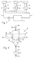
- Fig. 1 illustrates the principle of the oil circulating lubrication system of a paper machine, which comprises an oil tank 1, a lubrication oil pump 2 connected to the pressure side main piping 3, and a system of distribution pipes 4 branching out from the main piping to the objects of lubrication 5. From the objects of lubrication 5, return pipes 6 are connected to the return side main piping 7, through which the oil flows back into the oil tank 1. Placed in each one of the return pipes 6 at a point close to the object of lubrication 5 is a dehydrating unit 8.
- the dehydrating unit 8 consists of a vertical elongated container of a circular cross-section, a separation chamber 9 which has an upper part of a larger cross-section acting as a separator part 10 and tapering conically downward into a receiver part 11 in the lower part of the container.
- the entrance duct 13 for the return pipe 6 opens downward in the separator part 10 below the level of the oil surface 12 and the lower edge of the exit duct 14.
- the entrance duct 13 for the return pipe 6 opens downward in the separator part 10 below the level of the oil surface 12 and the lower edge of the exit duct 14.
- These vertical flows separated from each other form a flow damping area, which also constitutes an air trap in the flow, below which the cylindrical and conical separator part contains a turbulent flow in which the actual water separating action occurs.
- a replacement air duct with an air filter 20 and a valve 19, through which replacement air can flow when required into that part of the oil circulating lubrication system which lies between the dehydrating unit 8 and the oil tank 1.
- the dehydrating device presented in Fig. 2 works as follows. As oil gravitates down through the return pipe 6 via the entrance duct 13 into the separator part 10, the oil flow is smoothed and, due to the difference between the specific weight of oil and that of the water drops in it, the water drops flow downward into the receiver part 11 while the pure oil flows upward via the exit duct 14 and out of the dehydrating unit. As the tubular receiver part 11 has a relatively small cross-section, the oil flow in the separator part 10 cannot affect the water in the receiver part 11, but substantially all water in the form of drops in the oil is gathered and remains in the receiver part. At suitable intervals of time, i.e.
- the water can be removed manually by opening the valve 15. It is also possible to provide the device, in a manner known in itself, with various sensing systems for automatic removal of water from the receiver part when necessary or at regular intervals.
Landscapes
- Engineering & Computer Science (AREA)
- General Engineering & Computer Science (AREA)
- Mechanical Engineering (AREA)
- Treatment Of Sludge (AREA)
- Removal Of Floating Material (AREA)
- Compressor (AREA)
- Treatment Of Liquids With Adsorbents In General (AREA)
- Paper (AREA)
Claims (9)
- Un dispositif de séchage pour un système de lubrification par circulation d'huile comprenant un réservoir d'huile (1), une pompe (2) à huile de lubrification, des conduits (3) de côté pressurisé, des conduits (4) de distribution vers les objets à lubrifier (5), des conduits de retour (6) à partir des objets à lubrifier (5) et un système (7) de conduit principal,
et les conduits de retour (6, 7) à partir de l'objet à lubrifier (5) sont munis d'une unité de séchage, l'unité de séchage comprenant :caractérisé en ce que :une chambre (9) de séparation de forme allongée verticale, dont la partie supérieure comprend une partie de séparation (10) et dont la partie inférieure est d'une section transversale plus étroite que la section transversale de la partie supérieure, la partie inférieure formant une partie de réception (11);un passage (14) de sortie pour les conduits de retour, à partir de la partie supérieure de la chambre de séparation ;un passage (13) d'entrée pour les conduits de retour (6, 7); etune valve de sortie (15) à l'extrémité inférieure de la partie de réception,le passage (13) d'entrée débouche vers le bas dans la chambre de séparation à un niveau inférieur au bord inférieur du passage de sortie (14) ; etl'espace associé avec le passage de sortie dans la partie supérieure de la chambre de séparation est muni d'un passage (18) de remplacement d'air. - Dispositif de séchage selon la revendication 1, caractérisé en ce que le dispositif a une valve de sécurité (16) entre la partie (10) de séparation et la partie (11) de réception.
- Dispositif de séchage selon la revendication 1, caractérisé en ce que la partis (11) de réception est en matériau transparent.
- Dispositif de séchage selon la revendication 1, caractérisé en ce que le volume de la partie (19) de séparation est sensiblement plus grand que le volume de la partie de réception (11).
- Dispositif de séchage selon la revendication 1, caractérisé en ce que la partie (10) de séparation a une forme conique se rétrécissant vers le bas vers la partie (11) de réception.
- Dispositif de séchage selon la revendication 1, caractérisé en ce que l'extrémité inférieure de la partie de réception (11) est munie d'un collecteur (17).
- Dispositif de séchage selon la revendication 1, caractérisé en ce que le passage (18) de remplacement d'air est muni d'une valve (19) et d'un filtre à air (20).
- Dispositif de séchage selon l'une quelconque des revendications 1 à 7, caractérisé en ce que le conduit de retour à partir de chaque objet à lubrifier (5) est muni d'une unité (8) de séchage.
- Dispositif de séchage selon l'une quelconque des revendications 1 à 8, caractérisé en ce que l'unité de séchage (8) est reliée au conduit (6) de retour en un point situé immédiatement après l'objet à lubrifier.
Applications Claiming Priority (2)
| Application Number | Priority Date | Filing Date | Title |
|---|---|---|---|
| FI961114A FI103147B (fi) | 1996-03-08 | 1996-03-08 | Vedenpoistolaite kiertovoitelujärjestelmään |
| FI961114 | 1996-03-08 |
Publications (3)
| Publication Number | Publication Date |
|---|---|
| EP0794380A2 EP0794380A2 (fr) | 1997-09-10 |
| EP0794380A3 EP0794380A3 (fr) | 1998-04-15 |
| EP0794380B1 true EP0794380B1 (fr) | 2002-06-05 |
Family
ID=8545614
Family Applications (1)
| Application Number | Title | Priority Date | Filing Date |
|---|---|---|---|
| EP97660021A Expired - Lifetime EP0794380B1 (fr) | 1996-03-08 | 1997-03-04 | Dispositif d'élimination d'eau pour un système de lubrification à huile |
Country Status (3)
| Country | Link |
|---|---|
| EP (1) | EP0794380B1 (fr) |
| DE (1) | DE69712948T2 (fr) |
| FI (1) | FI103147B (fr) |
Families Citing this family (4)
| Publication number | Priority date | Publication date | Assignee | Title |
|---|---|---|---|---|
| FI104851B (fi) * | 1997-02-18 | 2000-04-14 | Safematic Oy | Sovitelma kiertovoitelujärjestelmän yhteydessä |
| US6715461B2 (en) * | 2001-08-27 | 2004-04-06 | Honda Giken Kogyo Kabushiki Kaisha | System for lubricating valve-operating mechanism in engine |
| JP3958054B2 (ja) * | 2002-01-31 | 2007-08-15 | 株式会社東芝 | 回転機械の軸受油循環系統の改修方法 |
| CN111810825A (zh) * | 2020-07-21 | 2020-10-23 | 中铁工程装备集团有限公司 | 一种掘进机润滑密封系统 |
Family Cites Families (3)
| Publication number | Priority date | Publication date | Assignee | Title |
|---|---|---|---|---|
| US2660309A (en) * | 1949-08-06 | 1953-11-24 | Bowser Inc | Lubricant conditioning apparatus |
| FI924468A0 (fi) * | 1992-10-05 | 1992-10-05 | Karibu Oy | System foer reglering av zenindelning och trycknivao i behaollare som ingaor i pappers- och andra maskinens cirkulationssmoerjkretsar och returroersystem |
| YU49049B (sh) * | 1995-06-07 | 2003-07-07 | Vladimir Pantić | Postupak za filtriranje, degazaciju, dehidraciju i odstranjivanje produkata starenja naftnih ulja |
-
1996
- 1996-03-08 FI FI961114A patent/FI103147B/fi active
-
1997
- 1997-03-04 DE DE69712948T patent/DE69712948T2/de not_active Expired - Fee Related
- 1997-03-04 EP EP97660021A patent/EP0794380B1/fr not_active Expired - Lifetime
Also Published As
| Publication number | Publication date |
|---|---|
| FI961114A0 (fi) | 1996-03-08 |
| FI961114L (fi) | 1997-09-09 |
| EP0794380A3 (fr) | 1998-04-15 |
| DE69712948T2 (de) | 2003-01-23 |
| FI103147B1 (fi) | 1999-04-30 |
| FI103147B (fi) | 1999-04-30 |
| DE69712948D1 (de) | 2002-07-11 |
| EP0794380A2 (fr) | 1997-09-10 |
Similar Documents
| Publication | Publication Date | Title |
|---|---|---|
| FI75139C (fi) | Foerfarande och apparatur foer avskiljning av olja fraon vatten. | |
| CA2023782C (fr) | Procede de purification du produit de condensation de systemes a air comprime | |
| US7364663B2 (en) | Filter system | |
| SU1655535A1 (ru) | Устройство дл двухступенчатой сепарации жидкостей различной плотности с автоматическим выпуском | |
| US12447432B2 (en) | Switchable two-stage coalescence separation system | |
| US5417848A (en) | Coalescence separator with changeable coalescence element | |
| US5296150A (en) | Water oil separator | |
| US6391198B1 (en) | Method and apparatus for sludge and oil separation from aqueous solutions/emulsions | |
| KR101933459B1 (ko) | 빗물 재활용 시스템 | |
| US6113676A (en) | Deaerator for use in lubrication systems | |
| US7172688B2 (en) | Mixed immiscible liquids vacuum, separation, and disposal method and system (Mod 1) | |
| US2193261A (en) | Apparatus for effecting the separation of commingled liquids | |
| EP0794380A2 (fr) | Dispositif d'élimination d'eau pour un système de lubrification à huile | |
| NO166166B (no) | Fremgangsmaate og anordning for aa skille legemer fra en vaeske. | |
| US6962656B2 (en) | Liquid reconditioning system including a venturi pump | |
| NO119779B (fr) | ||
| GB2435226A (en) | Separation apparatus and method | |
| KR200242426Y1 (ko) | 유수분리기 | |
| FI104851B (fi) | Sovitelma kiertovoitelujärjestelmän yhteydessä | |
| NO313448B1 (no) | Anordning ved posefilter | |
| EP3894517B1 (fr) | Système d'élimination de l'eau de l'huile | |
| SE0802079A1 (sv) | Anordning för separation av en lättare vätskefas från en tyngre processvätskefas, anläggning för rening av en recirkulerande processvätska medelst separationsanordningen, samt förfarande för att separera en lättare vätskefas från en tyngre processvätskefas | |
| JP2006118342A (ja) | 油水分離装置 | |
| WO1989007971A1 (fr) | Separateurs | |
| US20090107928A1 (en) | Paint spray booth sludge consolidation method and apparatus |
Legal Events
| Date | Code | Title | Description |
|---|---|---|---|
| PUAI | Public reference made under article 153(3) epc to a published international application that has entered the european phase |
Free format text: ORIGINAL CODE: 0009012 |
|
| AK | Designated contracting states |
Kind code of ref document: A2 Designated state(s): DE FR GB SE |
|
| PUAL | Search report despatched |
Free format text: ORIGINAL CODE: 0009013 |
|
| AK | Designated contracting states |
Kind code of ref document: A3 Designated state(s): DE FR GB SE |
|
| 17P | Request for examination filed |
Effective date: 19981005 |
|
| 17Q | First examination report despatched |
Effective date: 20000218 |
|
| GRAG | Despatch of communication of intention to grant |
Free format text: ORIGINAL CODE: EPIDOS AGRA |
|
| GRAG | Despatch of communication of intention to grant |
Free format text: ORIGINAL CODE: EPIDOS AGRA |
|
| GRAH | Despatch of communication of intention to grant a patent |
Free format text: ORIGINAL CODE: EPIDOS IGRA |
|
| GRAH | Despatch of communication of intention to grant a patent |
Free format text: ORIGINAL CODE: EPIDOS IGRA |
|
| GRAA | (expected) grant |
Free format text: ORIGINAL CODE: 0009210 |
|
| AK | Designated contracting states |
Kind code of ref document: B1 Designated state(s): DE FR GB SE |
|
| PG25 | Lapsed in a contracting state [announced via postgrant information from national office to epo] |
Ref country code: FR Free format text: LAPSE BECAUSE OF FAILURE TO SUBMIT A TRANSLATION OF THE DESCRIPTION OR TO PAY THE FEE WITHIN THE PRESCRIBED TIME-LIMIT Effective date: 20020605 |
|
| REG | Reference to a national code |
Ref country code: GB Ref legal event code: FG4D |
|
| REF | Corresponds to: |
Ref document number: 69712948 Country of ref document: DE Date of ref document: 20020711 |
|
| EN | Fr: translation not filed | ||
| PGFP | Annual fee paid to national office [announced via postgrant information from national office to epo] |
Ref country code: GB Payment date: 20030303 Year of fee payment: 7 |
|
| PGFP | Annual fee paid to national office [announced via postgrant information from national office to epo] |
Ref country code: DE Payment date: 20030324 Year of fee payment: 7 |
|
| PLBE | No opposition filed within time limit |
Free format text: ORIGINAL CODE: 0009261 |
|
| STAA | Information on the status of an ep patent application or granted ep patent |
Free format text: STATUS: NO OPPOSITION FILED WITHIN TIME LIMIT |
|
| 26N | No opposition filed |
Effective date: 20030306 |
|
| PG25 | Lapsed in a contracting state [announced via postgrant information from national office to epo] |
Ref country code: GB Free format text: LAPSE BECAUSE OF NON-PAYMENT OF DUE FEES Effective date: 20040304 |
|
| PG25 | Lapsed in a contracting state [announced via postgrant information from national office to epo] |
Ref country code: DE Free format text: LAPSE BECAUSE OF NON-PAYMENT OF DUE FEES Effective date: 20041001 |
|
| GBPC | Gb: european patent ceased through non-payment of renewal fee | ||
| PGFP | Annual fee paid to national office [announced via postgrant information from national office to epo] |
Ref country code: SE Payment date: 20080313 Year of fee payment: 12 |
|
| EUG | Se: european patent has lapsed | ||
| PG25 | Lapsed in a contracting state [announced via postgrant information from national office to epo] |
Ref country code: SE Free format text: LAPSE BECAUSE OF NON-PAYMENT OF DUE FEES Effective date: 20090305 |