EP0794430A2 - Verfahren und Vorrichtung zur Bestimmung und überprüfung von mit Verbundwerkstoffen reparierten Materialien - Google Patents
Verfahren und Vorrichtung zur Bestimmung und überprüfung von mit Verbundwerkstoffen reparierten Materialien Download PDFInfo
- Publication number
- EP0794430A2 EP0794430A2 EP96250231A EP96250231A EP0794430A2 EP 0794430 A2 EP0794430 A2 EP 0794430A2 EP 96250231 A EP96250231 A EP 96250231A EP 96250231 A EP96250231 A EP 96250231A EP 0794430 A2 EP0794430 A2 EP 0794430A2
- Authority
- EP
- European Patent Office
- Prior art keywords
- signal
- accordance
- area
- mechanical
- generating
- Prior art date
- Legal status (The legal status is an assumption and is not a legal conclusion. Google has not performed a legal analysis and makes no representation as to the accuracy of the status listed.)
- Withdrawn
Links
- 238000000034 method Methods 0.000 title claims abstract description 18
- 238000007689 inspection Methods 0.000 title claims abstract description 15
- 238000011156 evaluation Methods 0.000 title claims abstract description 13
- 230000008439 repair process Effects 0.000 claims abstract description 44
- 238000012360 testing method Methods 0.000 claims abstract description 26
- 238000012545 processing Methods 0.000 claims abstract description 5
- 230000004044 response Effects 0.000 claims description 21
- 230000005540 biological transmission Effects 0.000 claims description 4
- 239000002131 composite material Substances 0.000 abstract description 38
- 230000001066 destructive effect Effects 0.000 description 8
- 238000010586 diagram Methods 0.000 description 5
- 229910052782 aluminium Inorganic materials 0.000 description 4
- XAGFODPZIPBFFR-UHFFFAOYSA-N aluminium Chemical compound [Al] XAGFODPZIPBFFR-UHFFFAOYSA-N 0.000 description 4
- 230000008859 change Effects 0.000 description 4
- 230000032798 delamination Effects 0.000 description 2
- 238000001514 detection method Methods 0.000 description 2
- 238000005259 measurement Methods 0.000 description 2
- 229910052751 metal Inorganic materials 0.000 description 2
- 239000002184 metal Substances 0.000 description 2
- 239000000126 substance Substances 0.000 description 2
- 239000004593 Epoxy Substances 0.000 description 1
- 238000013016 damping Methods 0.000 description 1
- 239000002828 fuel tank Substances 0.000 description 1
- 238000002955 isolation Methods 0.000 description 1
- 239000000463 material Substances 0.000 description 1
- 238000012986 modification Methods 0.000 description 1
- 230000004048 modification Effects 0.000 description 1
- 230000008707 rearrangement Effects 0.000 description 1
- 238000006467 substitution reaction Methods 0.000 description 1
- 238000010408 sweeping Methods 0.000 description 1
- 238000001931 thermography Methods 0.000 description 1
- 238000002604 ultrasonography Methods 0.000 description 1
Images


Classifications
-
- G—PHYSICS
- G01—MEASURING; TESTING
- G01N—INVESTIGATING OR ANALYSING MATERIALS BY DETERMINING THEIR CHEMICAL OR PHYSICAL PROPERTIES
- G01N29/00—Investigating or analysing materials by the use of ultrasonic, sonic or infrasonic waves; Visualisation of the interior of objects by transmitting ultrasonic or sonic waves through the object
- G01N29/04—Analysing solids
- G01N29/12—Analysing solids by measuring frequency or resonance of acoustic waves
-
- G—PHYSICS
- G01—MEASURING; TESTING
- G01N—INVESTIGATING OR ANALYSING MATERIALS BY DETERMINING THEIR CHEMICAL OR PHYSICAL PROPERTIES
- G01N29/00—Investigating or analysing materials by the use of ultrasonic, sonic or infrasonic waves; Visualisation of the interior of objects by transmitting ultrasonic or sonic waves through the object
- G01N29/34—Generating the ultrasonic, sonic or infrasonic waves, e.g. electronic circuits specially adapted therefor
- G01N29/348—Generating the ultrasonic, sonic or infrasonic waves, e.g. electronic circuits specially adapted therefor with frequency characteristics, e.g. single frequency signals, chirp signals
-
- G—PHYSICS
- G01—MEASURING; TESTING
- G01N—INVESTIGATING OR ANALYSING MATERIALS BY DETERMINING THEIR CHEMICAL OR PHYSICAL PROPERTIES
- G01N2291/00—Indexing codes associated with group G01N29/00
- G01N2291/02—Indexing codes associated with the analysed material
- G01N2291/023—Solids
- G01N2291/0231—Composite or layered materials
-
- G—PHYSICS
- G01—MEASURING; TESTING
- G01N—INVESTIGATING OR ANALYSING MATERIALS BY DETERMINING THEIR CHEMICAL OR PHYSICAL PROPERTIES
- G01N2291/00—Indexing codes associated with group G01N29/00
- G01N2291/04—Wave modes and trajectories
- G01N2291/042—Wave modes
- G01N2291/0423—Surface waves, e.g. Rayleigh waves, Love waves
-
- G—PHYSICS
- G01—MEASURING; TESTING
- G01N—INVESTIGATING OR ANALYSING MATERIALS BY DETERMINING THEIR CHEMICAL OR PHYSICAL PROPERTIES
- G01N2291/00—Indexing codes associated with group G01N29/00
- G01N2291/10—Number of transducers
- G01N2291/102—Number of transducers one emitter, one receiver
Definitions
- the present invention relates to an apparatus and method for evaluation and inspection of structures and, in particular, to an apparatus and method for non-destructive evaluation and inspection of composite-repaired metal structures.
- Composite repair refers to the repair of a damaged structure (e.g., an aluminum aircraft wing panel having a damaged area) by adhesively bonding a composite material, such as a multiple ply composite material, to the damaged structure.
- NDE/I non-destructive evaluation and inspection
- NDE/I techniques utilize eddy-current, ultrasound, thermal imaging, laser, X-ray, etc. All of these techniques require substantial accessibility to the structure to be evaluated and inspected.
- performance of conventional NDE/I requires disassembly of the aircraft structure(s) to gain access to the inspection article.
- composite-repaired structural inspection such as inspection of a C-130 outer wing fuel tank, it requires upwards of 1300 man-hours to disassemble the aircraft structure to gain access to the inspection article for conventional NDE/I.
- an apparatus and method for non-destructive evaluation and inspection of a repaired area of a structure includes a signal generator for generating a first electrical signal.
- a transducer coupled to the signal generator and to the structure converts the first electrical signal into a mechanical signal for transmission through the repaired area of the structure.
- Another transducer coupled to the structure receives and converts the mechanical signal into a second electrical signal.
- the apparatus further includes a signal processor coupled to the second transducer for generating, in response to the second electrical signal, an output signal indicative of the present condition of the repaired area of the structure.
- the output signal is then used for comparison to a baseline reference signal to determine whether the repaired area of the structure is damaged.
- the baseline reference signal is generated after repair of the structure is accomplished.
- the signal processor includes an impedance analyzer for measuring the impedance response of the repaired area in relation to the frequency of the first electrical signal generated by the signal generator.
- the impedance response measured at the time of testing is compared with the impedance response measured at the time of repair of the structure (undamaged condition) to determine if the repaired area is damaged.
- the tester 10 includes a signal generator 12, a first transducer 16, a second transducer 18 and a signal processor 22.
- the signal generator 12 is a sine wave generator and the test signal 14 varies in frequency over time, such as a sine sweep over a predetermined frequency range.
- FIGURE 1 there is shown a composite-repaired structure 30 having a composite repair doubler 32 including a composite-repaired area 31.
- the structure 30 is a metal structure such as an aluminum plate.
- the composite repair doubler 32 is used to repair a damaged area of the structure 30 by having the composite repair doubler adhesively bonded onto the structure 30 to repair the damaged area.
- the composite repair doubler 32 covers the composite-repaired area 31. It is the integrity of the composite repair doubler 32 or area 31 that is tested by the present invention.
- the first transducer 16 is coupled to, or installed onto, the structure 30 near the composite repair doubler 32, as shown.
- the first transducer 16 is also electrically coupled to the signal generator 12 and receives the signal 14.
- the first transducer 16 converts the signal 14 into a mechanical signal and transmits the mechanical signal into the composite repair area 31 and through both the structure 30 and composite repair doubler 32.
- the second transducer 18 is also coupled to, or installed onto, the structure near the composite repair doubler 32, as shown.
- the transducers 16, 18 can be located in any configuration, with a preferred configuration such that an imaginary line drawn between the two transducers 16, 18 intersects a point on the composite repair doubler 32, i.e. in the area 31.
- the transducers 16, 18 are positioned diagonal to the corners of the doubler 32, as shown, such that the imaginary line drawn between the transers 16, 18 substantially intersects with the central region of the composite repair doubler 32 (area 31).
- the mechanical signal produced by he transducer 16 travels through both the structure 30 and the composite repair doubler 32 (area 31) and is received by the transducer 18.
- the transducer 18 converts the received mechanical signal into an electrical signal and outputs a response electrical signal 20.
- the transducers 16, 18 are piezoelectric transducers (PZT) whereby the first transducer 16 is a signal transmitter PZT and the second transducer 18 is a sensor PZT.
- the signal 20 is input to the signal processor 22 for processing to generate an output signal indicative of the present condition of the composite-repaired structure 30.
- Damage detection of the composite-repaired structure 30 i.e. damage of the composite repair doubler 32 in the form of delamination, disbond, crack propagation, etc.; and increased damage to the structure 30 such as crack propagation, etc.
- the baseline reference signal(s), representing the undamaged condition of the composite-repaired structure 30, is generated at the time of the composite repair of the structure 30.
- the baseline reference signal(s) is then stored for later use when the composite-repaired structure 30 is tested and inspected to determine the integrity (damaged or undamaged) of the repair after the composite-repaired structure 30 has been in use for some period of time.
- the signal processor 22 includes an isolation filter and amplifier 40, a frequency domain integrator 42, and a digital indicator 44.
- the response electrical signal 20 (the current test signal) output from the second transducer 18 is input to the filter and amplifier 40.
- the filter and amplifier 40 filters out any signals having frequencies outside the range of frequencies of the test electrical signal 14 generated by the signal generator 12, and further amplifies the filtered signal.
- the filtered signal referred to as the sine sweep response 41, is input to the frequency domain integrator 42.
- the frequency domain integrator 42 generates and outputs a DC signal 43 in response to the sine sweep response 41.
- the digital indicator 44 receives the DC signal 43 and provides a display (or value) indicative of the present condition of the composite-repaired structure 30. The display is thereafter read or stored by the user for comparison with the baseline reference signal(s).
- the composite repair doubler 32 possesses particular electro-mechanical admittance and/or impedance characteristics. These characteristics are determined by the physical and/or chemical properties of the materials of the composite repair doubler 32. These properties include inertia, spring and viscous damping designated by coefficients m, k and c, respectively, with the mechanical properties analogous to the electrical properties of inductance, capacitance and resistance. A change in the physical and/or chemical characteristics of the composite repair doubler 32 causes a corresponding change in the coefficients m, k or c. It is this change (difference measured at two different times) that is used to detect the presence of a damaged condition (delamination, disbond, crack propagation, etc.) of the composite repair doubler 32.
- FIGURE 3 there is shown an alternative embodiment of a tester 100 in accordance with the present invention.
- an impedance analyzer 102 is coupled to the test electrical signal 14 and the response electrical signal 20.
- the impedance analyzer 102 measures the impedance and/or admittance from the first transducer 16 to the second transducer 18.
- a damaged condition in the composite repair doubler 32 will result in an impedance response different from the impedance response (baseline reference signal) generated from an undamaged composite repair doubler 32.
- the impedance analyzer 102 is a Hewlett-Packard HP 4194A impedance analyzer capable of providing impedance signal response (magnitude and phase) graphs or plots in relation to frequency (of the test electrical signal 14).
- impedance signal response magnitude and phase
- any measuring equipment, and the like, capable of measuring any change(s) in the properties of the composite repair doubler 32 detected in response to the signal(s) passing through the composite repair doubler 32 may be used.
- a 14-ply B/Epoxy composite repair doubler 32 (7.5 inch length, 2.5 inch width, 0.1 inch thickness) was applied to an aluminum plate specimen 30.
- a thin metallic shim (1.25 inch length, 0.5 inch width, 0.05 inch thickness) was inserted between the composite repair doubler 32 and the aluminum plate specimen 30.
- test specimen was tested using the tester 10 in accordance with the test configuration shown in FIGURE 1.
- the digital readout from the signal processor 22 provided an output signal of "68".
- test specimen was tested using the tester 100 in accordance with the test configuration shown in FIGURE 3 whereby impedance-vs-frequency plots or graphs were obtained from the impedance analyzer 102.
- the thin metallic shim was removed from the composite repair doubler 32 to provide a damaged condition (disbond) for the composite repair doubler 32.
- the output signal from the tester 10 provided a reading of "92”.
- An output signal of "68” was generated by the tester 10 for an undamaged condition and an output signal of "92" for a damaged condition.
- impedance-vs-frequency plots or graphs were generated from the impedance analyzer 102 for the damaged condition.
- the graphs generated from the undamaged and damaged composite repair doubler were overlayed and the resulting graphs 200, 202 are shown in FIGURE 4.
- the solid line represents measurements for the undamaged condition and the dotted line represents measurements for the damaged condition.
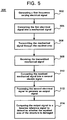
- the signal generator 12 generates the test electrical signal 14 for input to the first transducer 16.
- the frequency of the test electrical signal 14 varies according to a desired pattern (e.g. frequency sweeping from 18 KHz to 19 KHz over a time period T).
- the signal 14 may have a single frequency or a range of frequencies.
- the electrical signal 14 is converted into a mechanical signal. The mechanical signal is transmitted through the composite-repaired doubler 32 (i.e. the repaired area 31) at a step 306.
- the mechanical signal is received by the second transducer 18 at a step 308.
- the received mechanical signal is converted into the response electrical signal 20.
- the signal 20 is processed to generate a display signal at a step 312.
- the output signal is compared to a baseline reference signal to determine whether the composite-repaired doubler (the repaired area 31) of the structure 30 is damaged.
- an alternative embodiment of the method 300 includes repeating the steps 302 through 312 after the structure 30 is repaired with the composite repair doubler 32. Performance of these steps after repair of the structure will generate the baseline reference signal that is used, at step 314, for comparison to the output signal to determine if a damaged condition is present.
Landscapes
- Physics & Mathematics (AREA)
- General Physics & Mathematics (AREA)
- Pathology (AREA)
- Life Sciences & Earth Sciences (AREA)
- Chemical & Material Sciences (AREA)
- Analytical Chemistry (AREA)
- Biochemistry (AREA)
- Health & Medical Sciences (AREA)
- Immunology (AREA)
- General Health & Medical Sciences (AREA)
- Acoustics & Sound (AREA)
- Investigating Or Analyzing Materials By The Use Of Electric Means (AREA)
- Investigating Or Analyzing Materials By The Use Of Ultrasonic Waves (AREA)
- Measuring Instrument Details And Bridges, And Automatic Balancing Devices (AREA)
- Measurement Of Resistance Or Impedance (AREA)
- Testing Of Devices, Machine Parts, Or Other Structures Thereof (AREA)
Applications Claiming Priority (2)
| Application Number | Priority Date | Filing Date | Title |
|---|---|---|---|
| US612421 | 1996-03-07 | ||
| US08/612,421 US5665913A (en) | 1996-03-07 | 1996-03-07 | Method and apparatus for evaluation and inspection of composite-repaired structures |
Publications (2)
| Publication Number | Publication Date |
|---|---|
| EP0794430A2 true EP0794430A2 (de) | 1997-09-10 |
| EP0794430A3 EP0794430A3 (de) | 1999-03-10 |
Family
ID=24453086
Family Applications (1)
| Application Number | Title | Priority Date | Filing Date |
|---|---|---|---|
| EP96250231A Withdrawn EP0794430A3 (de) | 1996-03-07 | 1996-10-16 | Verfahren und Vorrichtung zur Bestimmung und überprüfung von mit Verbundwerkstoffen reparierten Materialien |
Country Status (5)
| Country | Link |
|---|---|
| US (2) | US5665913A (de) |
| EP (1) | EP0794430A3 (de) |
| JP (1) | JPH09243584A (de) |
| KR (1) | KR970066535A (de) |
| TW (1) | TW364058B (de) |
Cited By (1)
| Publication number | Priority date | Publication date | Assignee | Title |
|---|---|---|---|---|
| US7736452B2 (en) | 2001-12-22 | 2010-06-15 | Airbus Operations Limited | Method of forming and indirect testing of a bond on or in an aircraft component |
Families Citing this family (21)
| Publication number | Priority date | Publication date | Assignee | Title |
|---|---|---|---|---|
| US5665913A (en) * | 1996-03-07 | 1997-09-09 | E-Systems, Inc. | Method and apparatus for evaluation and inspection of composite-repaired structures |
| US6006163A (en) * | 1997-09-15 | 1999-12-21 | Mcdonnell Douglas Corporation | Active damage interrogation method for structural health monitoring |
| US6205859B1 (en) | 1999-01-11 | 2001-03-27 | Southwest Research Institute | Method for improving defect detectability with magnetostrictive sensors for piping inspection |
| US6732587B2 (en) | 2002-02-06 | 2004-05-11 | Lockheed Martin Corporation | System and method for classification of defects in a manufactured object |
| US20110001064A1 (en) * | 2002-06-06 | 2011-01-06 | Howard Letovsky | Self tuning frequency generator |
| US7312608B2 (en) * | 2005-11-03 | 2007-12-25 | The Boeing Company | Systems and methods for inspecting electrical conductivity in composite materials |
| US7891247B2 (en) * | 2007-05-16 | 2011-02-22 | The Boeing Company | Method and system for detecting an anomaly and determining its size |
| US8015877B2 (en) * | 2007-05-16 | 2011-09-13 | The Boeing Company | Imaging an anomaly using backscattered waves |
| US7734429B2 (en) * | 2007-10-15 | 2010-06-08 | Boeing Company | Method and apparatus for creating at least one parameter for algorithmically evaluating damage in a structure |
| US20090287085A1 (en) * | 2008-05-15 | 2009-11-19 | Shmuel Ben-Ezra | Device, system, and method of determining an acoustic contact between an ultrasonic transducer and a body |
| US8209838B2 (en) * | 2008-12-19 | 2012-07-03 | The Boeing Company | Repairing composite structures |
| US8499632B1 (en) | 2010-08-23 | 2013-08-06 | The Boeing Company | Characterizing anomalies in a laminate structure |
| US8831895B2 (en) | 2011-06-27 | 2014-09-09 | Honeywell International Inc. | Structural damage index mapping system and method |
| CN102944581B (zh) * | 2012-12-07 | 2014-10-15 | 大连理工大学 | 一种导管架海洋平台的结构损伤监测方法 |
| EP3066461A1 (de) * | 2013-11-08 | 2016-09-14 | Bombardier Inc. | Integritätsüberwachung von verbundstrukturen |
| AU2015333544B2 (en) | 2014-10-14 | 2021-02-25 | Inversa Systems Ltd. | Method of inspecting a degraded area of a metal structure covered by a composite repair and method of measuring a remaining wall thickness of a composite structure |
| JP6317708B2 (ja) | 2015-06-12 | 2018-04-25 | 株式会社Subaru | 超音波探傷システム、超音波探傷方法及び航空機構造体 |
| JP6758815B2 (ja) * | 2015-10-28 | 2020-09-23 | 三菱重工業株式会社 | 接合部評価方法 |
| JP7174236B2 (ja) * | 2018-11-15 | 2022-11-17 | 日本電信電話株式会社 | クラック検出装置とその方法 |
| NO20200190A1 (en) * | 2020-02-14 | 2021-08-16 | Optonor As | System and method for analysing an object |
| CN111579870B (zh) * | 2020-04-23 | 2022-07-26 | 南京邮电大学 | 结构件损伤监测与累积程度的诊断方法 |
Family Cites Families (18)
| Publication number | Priority date | Publication date | Assignee | Title |
|---|---|---|---|---|
| US3341774A (en) * | 1962-07-17 | 1967-09-12 | Comm Res Inc | Capacitance detector having a transmitter connected to one plate and a receiver connected to another plate |
| US3960004A (en) * | 1972-04-20 | 1976-06-01 | Lockheed Aircraft Corporation | Method for measuring impedance |
| US4109520A (en) * | 1976-03-30 | 1978-08-29 | Svenska Traforskningsinstitutet | Method and means for measuring web tension in paper or foils |
| US4301684A (en) * | 1980-01-31 | 1981-11-24 | Rockwell International Corporation | Ultrasonic non-destructive evaluation technique for structures of complex geometry |
| US4387601A (en) * | 1980-07-01 | 1983-06-14 | Hokushin Electric Works, Ltd. | Capacitance type displacement conversion device |
| NL8202942A (nl) * | 1982-07-21 | 1984-02-16 | Tno | Toestel voor het vaststellen van ijsafzetting of dergelijke. |
| US4519245A (en) * | 1983-04-05 | 1985-05-28 | Evans Herbert M | Method and apparatus for the non-destructive testing of materials |
| US4667149A (en) * | 1983-05-31 | 1987-05-19 | American Telephone And Telegraph Company, At&T Bell Laboratories | Precision nondestructive testing of metals |
| IT1206837B (it) * | 1987-01-09 | 1989-05-11 | Fiat Auto Spa | Procedimento e dispositivo per il controllo non distruttivo di puntidi saldatura di lamiera realizzati mediante saldatura elettrica |
| US4983034A (en) * | 1987-12-10 | 1991-01-08 | Simmonds Precision Products, Inc. | Composite integrity monitoring |
| GB8817725D0 (en) * | 1988-07-26 | 1988-09-01 | Matelect Ltd | Techniques to improve accuracy of measurement of crack depth by a c p d |
| US4956999A (en) * | 1988-11-30 | 1990-09-18 | Gp Taurio, Inc. | Methods and apparatus for monitoring structural members subject to transient loads |
| US5195046A (en) * | 1989-01-10 | 1993-03-16 | Gerardi Joseph J | Method and apparatus for structural integrity monitoring |
| US5093626A (en) * | 1990-05-11 | 1992-03-03 | E. I. Dupont De Nemours And Company | Contact measuring device for determining the dry film thickness of a paint on a conductive primer adhered to a plastic substrate |
| US5113079A (en) * | 1990-09-05 | 1992-05-12 | Matulka Robert D | Non-destructive testing of aircraft for structural integrity using holographic moire patterns |
| GB9023555D0 (en) * | 1990-10-30 | 1990-12-12 | Capcis Ltd | Detecting defects in concrete |
| US5374011A (en) * | 1991-11-13 | 1994-12-20 | Massachusetts Institute Of Technology | Multivariable adaptive surface control |
| US5665913A (en) * | 1996-03-07 | 1997-09-09 | E-Systems, Inc. | Method and apparatus for evaluation and inspection of composite-repaired structures |
-
1996
- 1996-03-07 US US08/612,421 patent/US5665913A/en not_active Expired - Lifetime
- 1996-10-16 EP EP96250231A patent/EP0794430A3/de not_active Withdrawn
- 1996-11-13 TW TW085113819A patent/TW364058B/zh active
-
1997
- 1997-02-26 KR KR1019970005954A patent/KR970066535A/ko not_active Withdrawn
- 1997-02-27 JP JP9058593A patent/JPH09243584A/ja active Pending
- 1997-05-21 US US08/861,165 patent/US5841031A/en not_active Expired - Lifetime
Cited By (1)
| Publication number | Priority date | Publication date | Assignee | Title |
|---|---|---|---|---|
| US7736452B2 (en) | 2001-12-22 | 2010-06-15 | Airbus Operations Limited | Method of forming and indirect testing of a bond on or in an aircraft component |
Also Published As
| Publication number | Publication date |
|---|---|
| JPH09243584A (ja) | 1997-09-19 |
| TW364058B (en) | 1999-07-11 |
| US5841031A (en) | 1998-11-24 |
| EP0794430A3 (de) | 1999-03-10 |
| KR970066535A (ko) | 1997-10-13 |
| US5665913A (en) | 1997-09-09 |
Similar Documents
| Publication | Publication Date | Title |
|---|---|---|
| US5665913A (en) | Method and apparatus for evaluation and inspection of composite-repaired structures | |
| EP0655623B1 (de) | Relative Resonanzfrequenzumtastung zur Feststellung von Rissen | |
| Hayashi et al. | Defect imaging with guided waves in a pipe | |
| US5351543A (en) | Crack detection using resonant ultrasound spectroscopy | |
| US5408880A (en) | Ultrasonic differential measurement | |
| Liu et al. | Adhesive debonding inspection with a small EMAT in resonant mode | |
| US4265120A (en) | Fatigue detection utilizing acoustic harmonics | |
| Dixon et al. | The analysis of adhesive bonds using electromagnetic acoustic transducers | |
| da Silva et al. | Development of circuits for excitation and reception in ultrasonic transducers for generation of guided waves in hollow cylinders for fouling detection | |
| US7231304B2 (en) | Interference pattern testing of materials | |
| WO2006110089A1 (en) | Method and apparatus for assessing quality of rivets using ultrasound | |
| Kline et al. | Nondestructive evaluation of adhesively bonded joints | |
| Cuc et al. | Disbond detection in adhesively bonded structures using piezoelectric wafer active sensors | |
| US6584848B1 (en) | Non-destructive evaluation method employing dielectric electrostatic ultrasonic transducers | |
| JPH11118771A (ja) | 板厚変化のある薄板の超音波探傷方法及び装置 | |
| US6343513B1 (en) | Non-destructive evaluation method and apparatus for measuring acoustic material nonlinearity | |
| Bar-Cohen et al. | Composite materials stiffness determination and defects characterization using enhanced leaky Lamb wave dispersion data acquisition method | |
| Aparna et al. | An effective sensor debond identification by employing wave energy-based signal analysis in isotropic plates utilizing ultrasonic guided waves | |
| Billson et al. | Laser-EMAT ultrasonic measurements of bonded metals | |
| Basu et al. | Guided Wave Resonance to Identify Damage in Thin Composite Plates | |
| Lalande et al. | Debond detection using broad-band high-frequency excitation and non-contacting laser vibrometer system | |
| Cawley | The sensitivity of an NDT instrument based on the membrane resonance method | |
| Hosten et al. | Air-coupled ultrasonic bulk waves to measure elastic constants in composite materials | |
| Chang et al. | Ultrasonic Evaluation of Adhesive Bond Strength Using Spectroscopic Techniques | |
| Grondel et al. | Study of fatigue crack in riveted plate by acoustic emission and Lamb wave analysis |
Legal Events
| Date | Code | Title | Description |
|---|---|---|---|
| PUAI | Public reference made under article 153(3) epc to a published international application that has entered the european phase |
Free format text: ORIGINAL CODE: 0009012 |
|
| AK | Designated contracting states |
Kind code of ref document: A2 Designated state(s): ES FR GB IT NL |
|
| PUAL | Search report despatched |
Free format text: ORIGINAL CODE: 0009013 |
|
| AK | Designated contracting states |
Kind code of ref document: A3 Designated state(s): ES FR GB IT NL |
|
| 17P | Request for examination filed |
Effective date: 19990908 |
|
| RAP1 | Party data changed (applicant data changed or rights of an application transferred) |
Owner name: RAYTHEON COMPANY |
|
| STAA | Information on the status of an ep patent application or granted ep patent |
Free format text: STATUS: THE APPLICATION HAS BEEN WITHDRAWN |
|
| 18W | Application withdrawn |
Withdrawal date: 20010606 |