EP0794468B1 - Méthode de développement à impression - Google Patents
Méthode de développement à impression Download PDFInfo
- Publication number
- EP0794468B1 EP0794468B1 EP97301430A EP97301430A EP0794468B1 EP 0794468 B1 EP0794468 B1 EP 0794468B1 EP 97301430 A EP97301430 A EP 97301430A EP 97301430 A EP97301430 A EP 97301430A EP 0794468 B1 EP0794468 B1 EP 0794468B1
- Authority
- EP
- European Patent Office
- Prior art keywords
- toner
- developing roller
- odd
- weight
- parts
- Prior art date
- Legal status (The legal status is an assumption and is not a legal conclusion. Google has not performed a legal analysis and makes no representation as to the accuracy of the status listed.)
- Expired - Lifetime
Links
- 238000000034 method Methods 0.000 title claims description 51
- 238000011161 development Methods 0.000 title claims description 38
- 239000002245 particle Substances 0.000 claims description 53
- 239000010419 fine particle Substances 0.000 claims description 46
- VYPSYNLAJGMNEJ-UHFFFAOYSA-N Silicium dioxide Chemical compound O=[Si]=O VYPSYNLAJGMNEJ-UHFFFAOYSA-N 0.000 claims description 24
- SZVJSHCCFOBDDC-UHFFFAOYSA-N iron(II,III) oxide Inorganic materials O=[Fe]O[Fe]O[Fe]=O SZVJSHCCFOBDDC-UHFFFAOYSA-N 0.000 claims description 20
- PNEYBMLMFCGWSK-UHFFFAOYSA-N Alumina Chemical compound [O-2].[O-2].[O-2].[Al+3].[Al+3] PNEYBMLMFCGWSK-UHFFFAOYSA-N 0.000 claims description 12
- 239000000377 silicon dioxide Substances 0.000 claims description 12
- XLOMVQKBTHCTTD-UHFFFAOYSA-N Zinc monoxide Chemical compound [Zn]=O XLOMVQKBTHCTTD-UHFFFAOYSA-N 0.000 claims description 6
- GWEVSGVZZGPLCZ-UHFFFAOYSA-N Titan oxide Chemical compound O=[Ti]=O GWEVSGVZZGPLCZ-UHFFFAOYSA-N 0.000 claims description 5
- 230000003746 surface roughness Effects 0.000 claims description 5
- OGIDPMRJRNCKJF-UHFFFAOYSA-N titanium oxide Inorganic materials [Ti]=O OGIDPMRJRNCKJF-UHFFFAOYSA-N 0.000 claims description 5
- 239000011787 zinc oxide Substances 0.000 claims description 3
- 230000000052 comparative effect Effects 0.000 description 26
- 239000003795 chemical substances by application Substances 0.000 description 23
- 229920001577 copolymer Polymers 0.000 description 19
- 229920005989 resin Polymers 0.000 description 17
- 239000011347 resin Substances 0.000 description 17
- -1 etc.) Chemical compound 0.000 description 16
- 239000000463 material Substances 0.000 description 12
- 239000006229 carbon black Substances 0.000 description 9
- 235000019241 carbon black Nutrition 0.000 description 9
- 238000012360 testing method Methods 0.000 description 9
- PPBRXRYQALVLMV-UHFFFAOYSA-N Styrene Chemical compound C=CC1=CC=CC=C1 PPBRXRYQALVLMV-UHFFFAOYSA-N 0.000 description 8
- 238000009826 distribution Methods 0.000 description 7
- 238000004519 manufacturing process Methods 0.000 description 7
- 239000000843 powder Substances 0.000 description 7
- UQSXHKLRYXJYBZ-UHFFFAOYSA-N Iron oxide Chemical compound [Fe]=O UQSXHKLRYXJYBZ-UHFFFAOYSA-N 0.000 description 6
- 239000003086 colorant Substances 0.000 description 6
- 230000000694 effects Effects 0.000 description 6
- 238000000227 grinding Methods 0.000 description 6
- 238000004898 kneading Methods 0.000 description 6
- 238000002156 mixing Methods 0.000 description 6
- 230000000704 physical effect Effects 0.000 description 6
- OKTJSMMVPCPJKN-UHFFFAOYSA-N Carbon Chemical compound [C] OKTJSMMVPCPJKN-UHFFFAOYSA-N 0.000 description 5
- 238000012674 dispersion polymerization Methods 0.000 description 5
- 239000005357 flat glass Substances 0.000 description 5
- 238000003756 stirring Methods 0.000 description 5
- 238000010558 suspension polymerization method Methods 0.000 description 5
- 238000010298 pulverizing process Methods 0.000 description 4
- IJGRMHOSHXDMSA-UHFFFAOYSA-N Atomic nitrogen Chemical compound N#N IJGRMHOSHXDMSA-UHFFFAOYSA-N 0.000 description 3
- 239000004743 Polypropylene Substances 0.000 description 3
- 150000001875 compounds Chemical class 0.000 description 3
- 235000014113 dietary fatty acids Nutrition 0.000 description 3
- 239000000975 dye Substances 0.000 description 3
- 239000000194 fatty acid Substances 0.000 description 3
- 229930195729 fatty acid Natural products 0.000 description 3
- 210000003746 feather Anatomy 0.000 description 3
- 229910052751 metal Inorganic materials 0.000 description 3
- 239000002184 metal Substances 0.000 description 3
- 238000005498 polishing Methods 0.000 description 3
- 229920001155 polypropylene Polymers 0.000 description 3
- XLYOFNOQVPJJNP-UHFFFAOYSA-N water Substances O XLYOFNOQVPJJNP-UHFFFAOYSA-N 0.000 description 3
- OZAIFHULBGXAKX-UHFFFAOYSA-N 2-(2-cyanopropan-2-yldiazenyl)-2-methylpropanenitrile Chemical compound N#CC(C)(C)N=NC(C)(C)C#N OZAIFHULBGXAKX-UHFFFAOYSA-N 0.000 description 2
- XFCMNSHQOZQILR-UHFFFAOYSA-N 2-[2-(2-methylprop-2-enoyloxy)ethoxy]ethyl 2-methylprop-2-enoate Chemical compound CC(=C)C(=O)OCCOCCOC(=O)C(C)=C XFCMNSHQOZQILR-UHFFFAOYSA-N 0.000 description 2
- SOGAXMICEFXMKE-UHFFFAOYSA-N Butylmethacrylate Chemical compound CCCCOC(=O)C(C)=C SOGAXMICEFXMKE-UHFFFAOYSA-N 0.000 description 2
- 239000004698 Polyethylene Substances 0.000 description 2
- 229920006311 Urethane elastomer Polymers 0.000 description 2
- 150000001338 aliphatic hydrocarbons Chemical class 0.000 description 2
- 230000007613 environmental effect Effects 0.000 description 2
- 150000004665 fatty acids Chemical class 0.000 description 2
- 238000010438 heat treatment Methods 0.000 description 2
- 238000002844 melting Methods 0.000 description 2
- 230000008018 melting Effects 0.000 description 2
- 239000011259 mixed solution Substances 0.000 description 2
- 239000000178 monomer Substances 0.000 description 2
- 229910052757 nitrogen Inorganic materials 0.000 description 2
- 229920000573 polyethylene Polymers 0.000 description 2
- 239000003381 stabilizer Substances 0.000 description 2
- 229920005792 styrene-acrylic resin Polymers 0.000 description 2
- 239000000725 suspension Substances 0.000 description 2
- 238000012935 Averaging Methods 0.000 description 1
- CTQNGGLPUBDAKN-UHFFFAOYSA-N O-Xylene Chemical compound CC1=CC=CC=C1C CTQNGGLPUBDAKN-UHFFFAOYSA-N 0.000 description 1
- 239000004793 Polystyrene Substances 0.000 description 1
- 229920007962 Styrene Methyl Methacrylate Polymers 0.000 description 1
- 239000006230 acetylene black Substances 0.000 description 1
- 239000000654 additive Substances 0.000 description 1
- 230000000996 additive effect Effects 0.000 description 1
- 125000001931 aliphatic group Chemical group 0.000 description 1
- 150000001336 alkenes Chemical group 0.000 description 1
- XYLMUPLGERFSHI-UHFFFAOYSA-N alpha-Methylstyrene Chemical compound CC(=C)C1=CC=CC=C1 XYLMUPLGERFSHI-UHFFFAOYSA-N 0.000 description 1
- 150000003927 aminopyridines Chemical class 0.000 description 1
- 239000000981 basic dye Substances 0.000 description 1
- 230000015572 biosynthetic process Effects 0.000 description 1
- 125000004432 carbon atom Chemical group C* 0.000 description 1
- 125000003178 carboxy group Chemical group [H]OC(*)=O 0.000 description 1
- 239000006231 channel black Substances 0.000 description 1
- 239000013522 chelant Substances 0.000 description 1
- 239000008119 colloidal silica Substances 0.000 description 1
- 238000007796 conventional method Methods 0.000 description 1
- 238000001816 cooling Methods 0.000 description 1
- 239000003431 cross linking reagent Substances 0.000 description 1
- 230000006866 deterioration Effects 0.000 description 1
- 229910001873 dinitrogen Inorganic materials 0.000 description 1
- 238000007599 discharging Methods 0.000 description 1
- 239000006185 dispersion Substances 0.000 description 1
- 238000001035 drying Methods 0.000 description 1
- 229920001971 elastomer Polymers 0.000 description 1
- 239000003822 epoxy resin Substances 0.000 description 1
- 239000005038 ethylene vinyl acetate Substances 0.000 description 1
- 239000000945 filler Substances 0.000 description 1
- 238000001914 filtration Methods 0.000 description 1
- ZZUFCTLCJUWOSV-UHFFFAOYSA-N furosemide Chemical compound C1=C(Cl)C(S(=O)(=O)N)=CC(C(O)=O)=C1NCC1=CC=CO1 ZZUFCTLCJUWOSV-UHFFFAOYSA-N 0.000 description 1
- 229920001519 homopolymer Polymers 0.000 description 1
- 230000002209 hydrophobic effect Effects 0.000 description 1
- 229920000554 ionomer Polymers 0.000 description 1
- 150000002576 ketones Chemical class 0.000 description 1
- 238000005259 measurement Methods 0.000 description 1
- 229910044991 metal oxide Inorganic materials 0.000 description 1
- 150000004706 metal oxides Chemical class 0.000 description 1
- ADFPJHOAARPYLP-UHFFFAOYSA-N methyl 2-methylprop-2-enoate;styrene Chemical compound COC(=O)C(C)=C.C=CC1=CC=CC=C1 ADFPJHOAARPYLP-UHFFFAOYSA-N 0.000 description 1
- 239000000203 mixture Substances 0.000 description 1
- 238000012986 modification Methods 0.000 description 1
- 230000004048 modification Effects 0.000 description 1
- 125000005609 naphthenate group Chemical group 0.000 description 1
- 125000004433 nitrogen atom Chemical group N* 0.000 description 1
- 150000002894 organic compounds Chemical class 0.000 description 1
- TWNQGVIAIRXVLR-UHFFFAOYSA-N oxo(oxoalumanyloxy)alumane Chemical compound O=[Al]O[Al]=O TWNQGVIAIRXVLR-UHFFFAOYSA-N 0.000 description 1
- 239000012188 paraffin wax Substances 0.000 description 1
- 239000005011 phenolic resin Substances 0.000 description 1
- 239000000049 pigment Substances 0.000 description 1
- 229920001200 poly(ethylene-vinyl acetate) Polymers 0.000 description 1
- 229920002037 poly(vinyl butyral) polymer Polymers 0.000 description 1
- 229920006122 polyamide resin Polymers 0.000 description 1
- 229920000647 polyepoxide Polymers 0.000 description 1
- 229920001225 polyester resin Polymers 0.000 description 1
- 239000004645 polyester resin Substances 0.000 description 1
- 239000003505 polymerization initiator Substances 0.000 description 1
- 238000006116 polymerization reaction Methods 0.000 description 1
- 229920000098 polyolefin Polymers 0.000 description 1
- 229920002223 polystyrene Polymers 0.000 description 1
- 229920005749 polyurethane resin Polymers 0.000 description 1
- 229920002451 polyvinyl alcohol Polymers 0.000 description 1
- 229920000915 polyvinyl chloride Polymers 0.000 description 1
- 239000004800 polyvinyl chloride Substances 0.000 description 1
- 230000002265 prevention Effects 0.000 description 1
- RAPZEAPATHNIPO-UHFFFAOYSA-N risperidone Chemical compound FC1=CC=C2C(C3CCN(CC3)CCC=3C(=O)N4CCCCC4=NC=3C)=NOC2=C1 RAPZEAPATHNIPO-UHFFFAOYSA-N 0.000 description 1
- 239000005060 rubber Substances 0.000 description 1
- 229960001860 salicylate Drugs 0.000 description 1
- 150000003839 salts Chemical class 0.000 description 1
- FZHAPNGMFPVSLP-UHFFFAOYSA-N silanamine Chemical class [SiH3]N FZHAPNGMFPVSLP-UHFFFAOYSA-N 0.000 description 1
- 229920002545 silicone oil Polymers 0.000 description 1
- 229920002050 silicone resin Polymers 0.000 description 1
- 239000000344 soap Substances 0.000 description 1
- 230000003068 static effect Effects 0.000 description 1
- 229920003048 styrene butadiene rubber Polymers 0.000 description 1
- 238000010557 suspension polymerization reaction Methods 0.000 description 1
- 239000006234 thermal black Substances 0.000 description 1
- 238000005406 washing Methods 0.000 description 1
- 239000001993 wax Substances 0.000 description 1
- 239000008096 xylene Substances 0.000 description 1
Images
Classifications
-
- G—PHYSICS
- G03—PHOTOGRAPHY; CINEMATOGRAPHY; ANALOGOUS TECHNIQUES USING WAVES OTHER THAN OPTICAL WAVES; ELECTROGRAPHY; HOLOGRAPHY
- G03G—ELECTROGRAPHY; ELECTROPHOTOGRAPHY; MAGNETOGRAPHY
- G03G15/00—Apparatus for electrographic processes using a charge pattern
- G03G15/06—Apparatus for electrographic processes using a charge pattern for developing
- G03G15/08—Apparatus for electrographic processes using a charge pattern for developing using a solid developer, e.g. powder developer
-
- G—PHYSICS
- G03—PHOTOGRAPHY; CINEMATOGRAPHY; ANALOGOUS TECHNIQUES USING WAVES OTHER THAN OPTICAL WAVES; ELECTROGRAPHY; HOLOGRAPHY
- G03G—ELECTROGRAPHY; ELECTROPHOTOGRAPHY; MAGNETOGRAPHY
- G03G13/00—Electrographic processes using a charge pattern
- G03G13/06—Developing
- G03G13/08—Developing using a solid developer, e.g. powder developer
-
- G—PHYSICS
- G03—PHOTOGRAPHY; CINEMATOGRAPHY; ANALOGOUS TECHNIQUES USING WAVES OTHER THAN OPTICAL WAVES; ELECTROGRAPHY; HOLOGRAPHY
- G03G—ELECTROGRAPHY; ELECTROPHOTOGRAPHY; MAGNETOGRAPHY
- G03G9/00—Developers
- G03G9/08—Developers with toner particles
-
- G—PHYSICS
- G03—PHOTOGRAPHY; CINEMATOGRAPHY; ANALOGOUS TECHNIQUES USING WAVES OTHER THAN OPTICAL WAVES; ELECTROGRAPHY; HOLOGRAPHY
- G03G—ELECTROGRAPHY; ELECTROPHOTOGRAPHY; MAGNETOGRAPHY
- G03G9/00—Developers
- G03G9/08—Developers with toner particles
- G03G9/0819—Developers with toner particles characterised by the dimensions of the particles
-
- G—PHYSICS
- G03—PHOTOGRAPHY; CINEMATOGRAPHY; ANALOGOUS TECHNIQUES USING WAVES OTHER THAN OPTICAL WAVES; ELECTROGRAPHY; HOLOGRAPHY
- G03G—ELECTROGRAPHY; ELECTROPHOTOGRAPHY; MAGNETOGRAPHY
- G03G9/00—Developers
- G03G9/08—Developers with toner particles
- G03G9/0827—Developers with toner particles characterised by their shape, e.g. degree of sphericity
-
- G—PHYSICS
- G03—PHOTOGRAPHY; CINEMATOGRAPHY; ANALOGOUS TECHNIQUES USING WAVES OTHER THAN OPTICAL WAVES; ELECTROGRAPHY; HOLOGRAPHY
- G03G—ELECTROGRAPHY; ELECTROPHOTOGRAPHY; MAGNETOGRAPHY
- G03G9/00—Developers
- G03G9/08—Developers with toner particles
- G03G9/097—Plasticisers; Charge controlling agents
-
- G—PHYSICS
- G03—PHOTOGRAPHY; CINEMATOGRAPHY; ANALOGOUS TECHNIQUES USING WAVES OTHER THAN OPTICAL WAVES; ELECTROGRAPHY; HOLOGRAPHY
- G03G—ELECTROGRAPHY; ELECTROPHOTOGRAPHY; MAGNETOGRAPHY
- G03G9/00—Developers
- G03G9/08—Developers with toner particles
- G03G9/097—Plasticisers; Charge controlling agents
- G03G9/09708—Inorganic compounds
Definitions
- the present invention relates to a method for impression development using a non-magnetic one-component toner as a developer, which is used for image forming devices such as electrostatic copying machines, laser printer devices, plain paper facsimile devices and the like.
- the method for impression development is a method of contacting a developing roller wherein a thin layer of a non-magnetic one-component toner is formed on the surface, with the surface of a photoconductor, and allowing the toner in the thin layer to electrostatically adhere to an electrostatic latent image of the surface of the photoconductor, thereby visualizing (developing) the electrostatic image to form a toner image.
- the amount of the toner held on the surface of the developing roller is controlled by using control means made of an elastic member such as rubber, etc., thereby adjusting the thickness of the thin layer formed on the surface of the developing roller.
- the elastic member is pressure-contacted with the developing roller by its elasticity, physical properties such as elasticity, hardness, etc. of the elastic member exert an influence directly on a pressure contacting force of the elastic member to the developing roller, which is an important factor for deciding the thickness of the thin layer, uniformity of the thickness of the thin layer, etc. Therefore, the following problems arise.
- a plate-like rigid member whose surface is smooth e.g. plate glass, etc.
- a plate-like rigid member whose surface is smooth (e.g. plate glass, etc.) is used as the above control means in the state where one smooth surface of the rigid member is pressure-contacted with the surface of the developing roller (see JP Laid-Open No. 7-36277 or corresponding US-A-5 450 176).
- the rigid member is pressure-contacted with the developing roller by the other member such as spring, etc. and the pressure contacting force in that case is not directly related to physical properties of the rigid member. Besides, the durability of the rigid member is higher than that of the elastic member, and the rigid member withstands use for a long period of time and, therefore, the above-mentioned problems of the elastic member do not arise.
- the thin layer of the toner formed on the developing roller becomes thinner at the part where fusing occurs.
- the thickness of the thin layer of the toner becomes non-uniform and unevenness of the image density occurs.
- traces are likely to remain as white streaks (streaks which occur in the rotative direction of the developing roller or photoconductor, and in the conveying direction of the paper) on the formed image.
- the present inventors have studied to improve the thermal or mechanical durability of the toner by increasing the molecular weight of the fixing resin constituting the toner or to improve the fluidity of the toner by increasing the amount of the fluidizing agent (e.g. fine particles whose mean particle diameter on the volume basis is about 0.01 ⁇ m) to be added to the toner, in order to prevent the toner from fusing to the rigid member.
- the fluidizing agent e.g. fine particles whose mean particle diameter on the volume basis is about 0.01 ⁇ m
- the toner having a shape which is quite different from the spherical form e.g. needle-like shape, scale-like shape, etc.
- the total thin layer formed on the developing roller becomes thin and the image density is lowered.
- the thickness of the thin layer becomes small, the stress applied to each toner becomes large and a problem such as fusing of the toner is liable to occur, similar to the above term (d).
- the first method for impression development of the present invention is characterized by a method for impression development which comprises forming a thin layer of a toner on the surface of a developing roller with a control means for adjusting an amount of the toner held on the surface of the developing roller, and developing an electrostatic latent image formed on a photoconductor by contacting the thin layer with the electrostatic latent image,
- the first method for impression development of the present invention it becomes possible to prevent with high certainty a toner from fusing to a rigid member as the control means, thereby forming an image having no image failures and good image quality.
- the second method for impression development of the present invention is characterized by a method for impression development which comprises forming a thin layer of a toner on the surface of a developing roller with a control means for adjusting an amount of the toner held on the surface of the developing roller, and developing an electrostatic latent image formed on a photoconductor by contacting the thin layer with the electrostatic latent image,
- the second method for impression development of the present invention it becomes possible to control a thin layer formed on a developing roller to a suitable thickness, thereby forming an image having no or acceptably few image failures and good image quality.
- the toner when the mean value of the odd-shape degree of the toner is less than 0.5, or when the proportion of the toner having the odd-shape degree of not more than 0.2 exceeds 20%, the toner has a shape, which is quite different from the spherical shape, and the proportion of the number of toners, which do not easily pass through the space between the rigid member and developing roller, becomes large. Accordingly, image failures such as the above-mentioned reduction in image density, unevenness, streak, etc. occur.
- the mean value of the odd-shape of the toner exceeds 0.8, the toner has a shape, which is almost the same as the spherical shape, and the proportion of the number of toners, which easily pass through the space between the rigid member and developing roller, becomes large. Accordingly, image failures such as the above-mentioned fog occurs in the formed image.
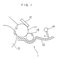
- Fig. 1 is a partially cross sectional view illustrating one embodiment of the developing device used in the present invention.
- a developing device 1 is equipped with a developing roller 11, a rigid member 12 as control means for forming a thin layer, a toner supplying roller 13 and stirring means 14 arranged behind the toner supplying roller 13, and the respective parts are contained in a device body 10.
- This developing device body 10 is arranged so that the surface of the developing roller 11 is pressure-contacted with the surface of a photoconductor 2 in an image forming device.
- the rigid member 12 has a plate-like shape and one surface thereof is pressure-contacted with the surface of the developing roller 11.
- the surface of the toner supplying roller 13 is also pressure-contacted with the surface of the developing roller 11.
- the developing roller 11 those wherein at least the surface is made of a flexible urethane rubber etc. are preferably used.
- the developing roller 11 having the flexible surface is not likely to damage the surface of the photoconductor 2 and has an effect of preventing the above-mentioned image failures (e.g. unevenness of the image density, streak, etc.) caused because the toner easily pass through the space between the rigid member and developing roller, to some extent.
- the hardness of the surface of the developing roller 11 is from 45 to 100, preferably 70 to 80, in Asker C.
- the hardness of the surface of the developing roller 11 exceeds the above range, there tends to arise a problem that the surface of the photoconductor 2 is liable to be damaged.
- the hardness of the surface of the developing roller 11 is smaller than the above range, the durability of the developing roller 11 tends to be lowered. Therefore, the developing roller 11 is liable to be worn, causing a fog in the formed image.
- the rigid member 12 to be pressure-contacted with the above developing roller 11 various plate materials of the rigid material can be used.
- a plate glass is preferably used, as described above, in view of smoothness of the surface as a surface to be pressure-contacted with the developing roller 11 or whole rigidity.
- the surface of the above rigid member 12 is smooth. Specifically, the surface roughness Ra is not more than 0.2, preferably from 0.001 to 0.1. When the surface roughness Ra of the rigid member 12 exceeds the above range, there tends to arise a problem that the toner is liable to fuse to the rigid member 12.
- the rigid member 12 is pressure-contacted with the surface of the developing roller 11 in a predetermined pressure contacting force by pressure contacting means (not shown) (e.g. spring, etc.).
- pressure contacting means e.g. spring, etc.
- the developing roller 11 is pressure-contacted with the surface of the photoconductor 2 in a predetermined pressure contacting force by pressure contacting means (not shown) (e.g. spring, etc.).
- the pressure contacting force applied when the rigid member 12 is pressure-contacted with the surface of the developing roller 11 is preferably from 4 to 15 g/mm, more preferably from 7 to 12 g/mm, in linear pressure.
- the pressure contacting force is smaller than the above wider range, an effect of controlling the amount of the toner tends to become insufficient and it becomes less easy to form the thin layer of the toner on the developing roller 11.
- the pressure contacting force exceeds the above range, the surface of the developing roller 11 is likely to be damaged.
- Impression development of the static latent image using the above developing device 1 is conducted by the following procedure.
- the photoconductor 2, developing roller 11, toner supplying roller 13 and stirring means 14 are rotated in the direction of the arrows shown in the figure at a predetermined rotation rate.
- the toner (not shown) which is stirred by the stirring means 14 and supplied to the surface of the developing roller 11 by the toner supplying roller 13, is charged by friction with the developing roller 11 and held on the surface of the developing roller 11.
- the amount of the toner held is controlled by the rigid member 12 as control means and, at the same time, the toner adheres to the surface of the developing roller 11 by an action of an image force of the rigid member 12, thereby forming a thin layer of the toner on the surface of the developing roller 11.
- an electrostatic latent image corresponding to the formed image is formed on the surface of the photoconductor 2 through the steps of charging and exposure.
- the steps of impression development has been accomplished.
- the method for impression development includes so-called "negative-positive reversal development” wherein a photoconductor and a toner, which are charged to the same polarity each other, are used in combination and the toner is allowed to selectively adhere to the part whose potential was reduced by exposure among the uniformly charged surface of the photoconductor, thereby forming a toner image, and so-called “positive-positive development” wherein a photoconductor and a toner, which are charged to the reverse polarity each other, are used in combination and the toner is allowed to selectively adhere to the part whose potential was not reduced by exposure among the uniformly charged surface of the photoconductor, thereby forming a toner image.
- the method for impression development of the present invention can be applied to any one of both systems.
- the toner used for the method for impression development may be any one of the toner in the above first invention and toner in the above second invention.
- the toner in the first invention may be one prepared by adding inorganic fine particles having a mean particle diameter of 0.1 to 1.0 ⁇ m on the volume basis as an additive in an amount x (parts by weight), based on 100 parts by weight of the toner, which satisfies the following expression (i). 0.1 ⁇ x ⁇ 1.5 This reason is as described above.
- Examples of the above inorganic fine particles include fine particles of magnetite (e.g. iron oxide (III), iron oxide (II), etc.), aluminum oxide, silica, titanium oxide and zinc oxide, but are not limited thereto.
- fine particles of magnetite is preferably used because they are superior in polishing effect of the fused toner and cause little wear of drum.
- the fine particles of magnetite are mainly supplied in the spherical shape or cubic shape. In the present invention, fine particles having any shape may be used alone, or fine particles having the spherical shape and those having the cubic shape may be used in combination.
- the mean particle diameter on the volume basis of magnetite fine particles is preferably from about 0.3 to 0.7 ⁇ m within the above range, taking the polishing effect of the fused toner and prevention of wear of drum into consideration.
- the amount of magnetite fine particles added based on 100 parts by weight of the toner is preferably not less than 0.3 parts by weight, more preferably from about 0.5 to 0.7 parts by weight, within the above range, taking coexistence of the above both effects into consideration.
- fine particles whose particle diameter is smaller than that of the above inorganic fine particles as the abrasive by about one order i.e. fine particles having a primary mean particle diameter on the volume basis of the order of 10 nm may be added as the fluidizing agent as usual.
- the fluidizing agent there can be used fine powders of metal oxides such as aluminium oxide, silica, titanium oxide, zinc oxide, etc. and various fine particles which have hitherto been known, such as fluororesin fine particles, etc.
- a silica surface treating agent containing hydrophobic or hydrophilic silica fine particles, such as ultrafine silica anhydride, colloidal silica, etc. is preferably used.
- the amount of the fluidizing agent added is not specifically limited, and may be the same as that used in a conventional method. Specifically, the fluidizing agent is preferably added in the total amount from about 0.1 to 3.0 parts by weight based on 100 parts by weight of the toner. Sometimes, the amount may be out of this range.
- the toner in the first invention i.e. toner wherein the above-mentioned abrasive and fluidizing agent are added
- those produced by the grinding method are preferably used as usual.
- the toner is obtained as follows. First, the colorant and other components are added to the fixing resin, followed by homogeneously premixing with a dry blender, Henschel mixer, ball mill and the like. The resulting mixture is uniformly molten and kneaded, using a kneading device such as Banbury mixer, roll, single- or twin-screw kneading extruder, etc., and then the resulting kneaded product is cooled, ground and optionally classified to obtain a toner.
- a kneading device such as Banbury mixer, roll, single- or twin-screw kneading extruder, etc.
- this first invention it is also possible to use a toner having a shape, which is almost the same as the spherical shape, produced by the producing method utilizing a suspension polymerization method, dispersion polymerization method, etc., in addition to the toner obtained by the above grinding method. Since the toner having a shape, which is almost the same as the spherical shape, easily pass through the space between the rigid member as control means and developing roller, it is preferred to use those having an odd-shape obtained by the method described hereinafter in the step after the production of the toner, or in the production process.
- the proportion of the number of toners becomes, the better. It is ideal that the proportion is 0%, that is, the toner having the odd-shape degree of not more than 0.2 is not contained at all. Therefore, the lower limitation of the proportion of the number of toners having the odd-shape degree of not more than 0.2 is not defined.
- the mean value of the odd-shape degree of the toner is determined by measuring each minimum diameter and maximum diameter of the predetermined number of toners extracted as the sample, using a microscope etc., calculating the data of the odd-shape degree by the above equation (i), and averaging the data.
- the proportion of the number of toners having the odd-shape degree of not more than 0.2 is obtained by determining the number of toners having the odd-shape degree of not more than 0.2 from the measuring results of the odd-shape degree in the above predetermined number of toners, and calculating the percentage of them to the total number of measurement.
- the average of the odd-shape degree of the toner and proportion of the number of toners having the odd-shape degree of not more than 0.2 are determined by setting the number of toners as the sample to 100.
- toner in the second invention those produced by the grinding method are preferably used in the same manner as in the toner in the first invention.
- conditions of grinding may be adjusted.
- the mean value of the odd-shape degree of the toner is liable to become smaller and the proportion of the number of toners having the odd-shape degree of not more than 0.2 is liable to become larger.
- the mean value of the odd-shape degree of the toner is liable to become larger and the proportion of the number of toners having the odd-shape degree of not more than 0.2 is liable to become smaller.
- a toner having a nearly spherical shape produced by the process utilizing a suspension polymerization method, a dispersion polymerization method, etc. can be modified into those having an odd-shape by any means described hereinafter in the step after the production of the toner, or in the production process.
- the second invention it is possible to use a toner whose distribution of the odd-shape degree of the toner particle after modification (mean value of the odd-shape degree of the toner particle and the proportion of the number of toner particles having the odd-shape degree of not more than 0.2) is within the above range defined in the present invention, even if the toner is produced by the process utilizing a suspension polymerization method, the dispersion polymerization method, etc.
- Examples of the method of modifying the toner having the nearly spherical shape, produced by the producing method utilizing a suspension polymerization method, dispersion polymerization method, etc. into a toner having an odd-shape include a method of cohering fine particles to form a toner particle having a particle diameter of a few ⁇ m; a method of modifying the toner particle by impregnating water into the toner during polymerization process and then heating it; and the like.
- the toner in the first and second inventions has a median size of about 6.0 to 12.0 ⁇ m and a mean particle diameter on the volume basis of about 8 to 11 ⁇ m.
- the median size of the toner is preferably not more than 10 ⁇ m, but a normal toner having a particle diameter of more than 10 ⁇ m may be used.
- a volume resistivity of the toner is preferably not less than 10 8 ⁇ cm, taking charging characteristics into consideration.
- Examples of the fixing resin constituting the toner produced by the above grinding method include styrene resin (homopolymer or copolymer containing styrene or a styrene substitute) such as polystyrene, chloropolystyrene, poly- ⁇ -methylstyrene, styrene-chlorostyrene copolymer, styrene-propylene copolymer, styrene-butadiene copolymer, styrene-vinyl chloride copolymer, styrene-vinyl acetate copolymer, styrene-maleic acid copolymer, styrene-acrylate copolymer (e.g.,
- styrene-methyl acrylate copolymer styrene-ethyl acrylate copolymer, styrene-butyl acrylate copolymer, styrene-octyl acrylate copolymer, styrene-phenyl acrylate copolymer, etc.
- styrene-methacrylate copolymer e.g.
- styrene-methyl methacrylate copolymer styrene-ethyl methacrylate copolymer, styrene-butyl methacrylate copolymer, styrene-phenyl methacrylate copolymer, etc.
- colorant there can be used various dyes, pigments, etc. including those which have hitherto been known.
- carbon black is mainly used in case of a black toner.
- the carbon black there can be used various carbon blacks which have hitherto been known, such as channel black, roller black, disk black, gas furnace black, oil furnace black, thermal black, acetylene black and the like.
- An amount of carbon black added to the fixing resin is not specifically limited. However, since carbon black itself has an electroconductivity, it also serve as means for controlling electric characteristics which exerts an influence on charging properties of the toner. Accordingly, it is preferred to set the preferable range of the amount added according to the desired performances of the toner (particularly, above-mentioned volume resistivity).
- the amount of carbon black added is not specifically limited, but is preferably from about 1 to 9 parts by weight based on 100 parts by weight of the fixing resin, in view of charging properties of the developer.
- Examples of the other components to be added to the fixing resin, together with the colorant include electric charge controlling material, release agent (anti-offset agent) and various stabilizers.
- any one of two electric charge controlling materials for controlling a positive charge and a negative charge may be used according to the charged polarity of the toner.
- an electric charge controlling material which has a counter charge polarity may be added in a fine amount, in addition to the main electric charge controlling material.
- Examples of the electric charge controlling material for controlling a positive charge include organic compounds containing a basic nitrogen atom, such as basic dyes, aminopyridine, pyrimidine compound, polynuclear polyamino compound, aminosilanes, etc., and fillers surface-treated with the above compounds.
- Examples of the electric charge controlling material for controlling a negative electric charge include compound containing a carboxyl group (e.g. metal chelate alkyl salicylate, etc.), metal complex salt dyes, fatty acid soap, metal naphthenate, oil-soluble dyes (e.g. nigrosine base (C.I. 5045), oil black (C.I. 26150), bontron S, spiron black, etc.) and electric charge controlling resins (CCR) (e.g. styrene-styrene sulfonate copolymer, etc.).
- a carboxyl group e.g. metal chelate alkyl salicylate, etc.
- metal complex salt dyes e.g. nigrosine base (C.I. 5045), oil black (C.I. 26150), bontron S, spiron black, etc.
- CCR electric charge controlling resins
- the electric charge controlling material is preferably added in the amount of 0.1 to 10 parts by weight, more preferably 0.5 to 5 parts by weight, based on 100 parts by weight of the fixing resin.
- release agent examples include aliphatic hydrocarbons, aliphatic metal salts, higher fatty acids, fatty acid esters or partially saponified materials thereof, silicone oil, various waxes and the like.
- aliphatic hydrocarbons having a weight-average molecular weight of about 1,000 to 10,000 are preferred.
- examples thereof include low-molecular weight polypropylene, low-molecular weight polyethylene, paraffin wax, low-molecular weight olefin polymer of an olefin unit having not fewer than 4 carbon atoms, and they may be suitably used alone or in combination thereof.
- the release agent is preferably added in the amount of 0.1 to 10 parts by weight, more preferably 0.5 to 8 parts by weight, based on 100 parts by weight of the fixing resin.
- silica fine powders having a primary mean particle diameter on the volume basis of 16 nm and magnetite fine particles (abrasive) having a mean particle diameter on the volume basis of 0.3 ⁇ m, followed by mixing with Henschel mixer to produce a positive charging type non-magnetic one-component developer.
- the amount of the magnetite fine particles added based on 100 parts by weight of the toner is 0.1 parts by weight (Example 1), 0.3 parts by weight (Example 2), 0.5 parts by weight (Example 3), 0.7 parts by weight (Example 4), 1.0 parts by weight (Example 5) or 1.5 parts by weight (Comparative Example 2).
- a developer wherein no magnetite fine particle was added was taken as Comparative Example 1.
- a developing device 1 used for the practical machine test has a structure shown in Fig. 1, wherein a developing roller 11 made of an urethane rubber and a rigid member 12 made of a plate glass are combined.
- the developing device 1 was used in combination with a positive charging type organic photoconductor 2.
- a hardness of the surface of the developing roller 11 was 76 in Asker C.
- a surface roughness Ra of the rigid member 12 was 0.01, and a pressure contacting force of this rigid member 12 to the developing roller 11 was 7.09 g/mm in linear pressure.
- silica fine powders having a primary mean particle diameter on the volume basis of 16 nm and magnetite fine particles (abrasive) having a mean particle diameter on the volume basis of 0.7 ⁇ m, followed by mixing with Henschel mixer to produce a positive charging type non-magnetic one-component developer.
- the amount of the magnetite fine particles added based on 100 parts by weight of the toner is 0.1 parts by weight (Example 6), 0.3 parts by weight (Example 7), 0.5 parts by weight (Example 8), 0.7 parts by weight (Example 9), 1.0 parts by weight (Example 10) or 1.5 parts by weight (Comparative Example 3).
- Example 11 To 100 parts by weight of the toner produced in Reference Example 1 were added 0.3 parts by weight of silica fine powders (fluidizing agent) having a primary mean particle diameter on the volume basis of 16 nm and aluminium oxide fine particles (abrasive) having a mean particle diameter on the volume basis of 0.5 ⁇ m, followed by mixing with Henschel mixer to produce a positive charging type non-magnetic one-component developer.
- the amount of the aluminium oxide fine particles added based on 100 parts by weight of the toner is 0.1 parts by weight (Example 11), 0.5 parts by weight (Example 12) or 1.0 parts by weight (Example 13).
- Example 14 To 100 parts by weight of the toner produced in Reference Example 1 were added 0.3 parts by weight of silica fine powders (fluidizing agent) having a primary mean particle diameter on the volume basis of 16 nm and titanium oxide fine particles (abrasive) having a mean particle diameter on the volume basis of 0.4 ⁇ m, followed by mixing with Henschel mixer to produce a positive charging type non-magnetic one-component developer.
- the amount of the titanium oxide fine particles added based on 100 parts by weight of the toner is 0.1 parts by weight (Example 14), 0.5 parts by weight (Example 15) or 1.0 parts by weight (Example 16).
- the mean value of the odd-shape degree of this toner and proportion of the number of toners having the odd-shape degree of not more than 0.2 were determined.
- the mean value of the odd-shape degree of the toner was 0.8 and the proportion of the number of toners having the odd-shape degree of not more than 0.2 was 15%.
- the mean value of the odd-shape degree of this toner and proportion of the number of toners having the odd-shape degree of not more than 0.2 were determined.
- the mean value of the odd-shape degree of the toner was 0.5 and the proportion of the number of toners having the odd-shape degree of not more than 0.2 was 25%.
- the above monomer phase mixed solution was mixed with an aqueous dispersing medium comprising the following respective components, followed by stirring at 10,000 r.p.m. with the aforecited high-speed stirrer for 10 minutes to prepare a suspension wherein a mean particle diameter of droplets is 10.5 ⁇ m.
- aqueous dispersing medium comprising the following respective components, followed by stirring at 10,000 r.p.m. with the aforecited high-speed stirrer for 10 minutes to prepare a suspension wherein a mean particle diameter of droplets is 10.5 ⁇ m.
- Components Parts by weight
- the above suspension was transferred to a 3 liter separable flask equipped with a stirrer, a nitrogen introducing tube and a condenser, wherein the interior is substituted with nitrogen gas, and polymerized by heating to 80°C with stirring at 120 r.p.m. for 5 hours, followed by cooling to room temperature.
- the mean value of the odd-shape degree of this toner and proportion of the number of toners having the odd-shape degree of not more than 0.2 were determined.
- the mean value of the odd-shape degree of the toner was 0.9 and the proportion of the number of toners having the odd-shape degree of not more than 0.2 was 0%.
- a thickness ( ⁇ m) of the thin layer was measured at five points in the width direction of the developing roller 11.
- points A to E were selected from one end side (driving side) connected with a driving gear to the other end side (driven side) of the developing roller 11.
- the results are shown in Table 5, together with the mean value of the odd-shape degree of the toner (A DF ) and proportion of the number of toners having the odd-shape degree of not more than 0.2 (DF 0.2 (%)) in the toners of the respective Examples and Comparative Examples.
Landscapes
- Physics & Mathematics (AREA)
- General Physics & Mathematics (AREA)
- Chemical & Material Sciences (AREA)
- Inorganic Chemistry (AREA)
- Developing Agents For Electrophotography (AREA)
Claims (14)
- Un procédé de développement par impression qui comprend la formation d'une couche mince de toner sur la surface d'un cylindre de développement, avec un moyen de commande pour ajuster la quantité de toner maintenue sur la surface du cylindre de développement, et le développement d'une image électrostatique latente formée sur un photoconducteur par mise en contact de la couche mince avec l'image électrostatique latente,
ledit moyen de commande comprenant un organe rigide en forme de plaque dont une surface est mise en contact de pression avec la surface du cylindre de développement,
caractérisé en ce que ledit toner comprend des particules de toner et des particules inorganiques fines qui ont un diamètre de particules moyen de 0,1 à 1,0 µm sur la base du volume et qui sont ajoutées aux particules de toner en quantité x (parties en poids) satisfaisant l'expression suivante : - Un procédé de développement par impression selon la revendication 1,
dans lequel les particules inorganiques fines comprennent au moins un corps sélectionné dans le groupe constitué par une magnétite, un oxyde d'aluminium, une silice, un oxyde de titane et un oxyde de zinc. - Un procédé de développement par impression selon la revendication 2,
dans lequel les particules inorganiques fines comprennent une magnétite. - Un procédé de développement par impression selon la revendication 3,
dans lequel le diamètre de particules moyen sur la base du volume de la magnétite est de 0,3 à 0,7 µm et la quantité de magnétite ajoutée, basée sur 100 parties en poids de particules de toner, est de 0,3 à 1,5 partie en poids. - Un procédé de développement par impression selon la revendication 1,
dans lequel la dimension médiane du toner est de 6,0 à 12,0 µm. - Un procédé de développement par impression selon la revendication 1,
dans lequel la rugosité superficielle Ra de l'organe rigide mis en contact de pression avec le cylindre de développement n'est pas supérieure à 0,2 µm. - Un procédé de développement par impression selon la revendication 1,
dans lequel la force de mise en contact de pression de l'organe rigide sur le cylindre de développement est de 4 à 15 g/mm en pression linéaire. - Un procédé de développement par impression selon la revendication 1,
dans lequel la dureté de la surface du cylindre de développement est de 45 à 100 en Asker C. - Un procédé de développement par impression qui comprend la formation d'une couche mince de toner sur la surface d'un cylindre de développement, avec un moyen de commande pour ajuster la quantité de toner maintenue sur la surface du cylindre de développement, et le développement d'une image électrostatique latente formée sur un photoconducteur par mise en contact de la couche mince avec l'image électrostatique latente,
ledit moyen de commande comprenant un organe rigide en forme de plaque dont une surface est mise en contact de pression avec la surface du cylindre de développement, caractérisé en ce que ledit toner comprend des particules de toner dans lesquelles la valeur moyenne d'un degré de forme dépareillée, déterminé à partir d'un diamètre minimal et d'un diamètre maximal de chaque particule de toner, par l'équation (ii) suivante : - Un procédé de développement par impression selon la revendication 9,
dans lequel la dimension médiane du toner est de 6,0 à 12,0 µm. - Un procédé de développement par impression selon la revendication 9,
dans lequel la rugosité superficielle Ra de l'organe rigide mis en contact de pression avec le cylindre de développement n'est pas supérieure à 0,2 µm. - Un procédé de développement par impression selon la revendication 9,
dans lequel la force de mise en contact de pression de l'organe rigide sur le cylindre de développement est de 4 à 15 g/mm en pression linéaire. - Un procédé de développement par impression selon la revendication 9,
dans lequel la dureté de la surface du cylindre de développement est de 45 à 100 en Asker C. - Un procédé de développement par impression qui comprend la formation d'une couche mince de toner sur la surface d'un cylindre de développement, avec un moyen de commande pour ajuster la quantité de toner maintenue sur la surface du cylindre de développement, et le développement d'une image électrostatique latente formée sur un photoconducteur par mise en contact de la couche mince avec l'image électrostatique latente,
ledit moyen de commande comprenant un organe rigide en forme de plaque dont une surface est mise en contact de pression avec la surface du cylindre de développement, caractérisé en ce que ledit toner comprend des particules de toner et des particules inorganiques fines qui ont un diamètre de particules moyen de 0,1 à 1,0 µm sur la base du volume et qui sont ajoutées aux particules de toner en quantité x (parties en poids) satisfaisant l'expression suivante :
Applications Claiming Priority (6)
| Application Number | Priority Date | Filing Date | Title |
|---|---|---|---|
| JP4774796A JPH09244290A (ja) | 1996-03-05 | 1996-03-05 | 接触現像方法 |
| JP47747/96 | 1996-03-05 | ||
| JP47749/96 | 1996-03-05 | ||
| JP4774796 | 1996-03-05 | ||
| JP4774996A JPH09244405A (ja) | 1996-03-05 | 1996-03-05 | 接触現像方法 |
| JP4774996 | 1996-03-05 |
Publications (3)
| Publication Number | Publication Date |
|---|---|
| EP0794468A2 EP0794468A2 (fr) | 1997-09-10 |
| EP0794468A3 EP0794468A3 (fr) | 1998-01-21 |
| EP0794468B1 true EP0794468B1 (fr) | 2001-01-10 |
Family
ID=26387919
Family Applications (1)
| Application Number | Title | Priority Date | Filing Date |
|---|---|---|---|
| EP97301430A Expired - Lifetime EP0794468B1 (fr) | 1996-03-05 | 1997-03-04 | Méthode de développement à impression |
Country Status (5)
| Country | Link |
|---|---|
| US (1) | US5702857A (fr) |
| EP (1) | EP0794468B1 (fr) |
| KR (1) | KR970066752A (fr) |
| DE (1) | DE69703854T2 (fr) |
| TW (1) | TW336289B (fr) |
Families Citing this family (2)
| Publication number | Priority date | Publication date | Assignee | Title |
|---|---|---|---|---|
| JP3733706B2 (ja) * | 1997-08-29 | 2006-01-11 | コニカミノルタビジネステクノロジーズ株式会社 | 一成分現像用負荷電性トナー及び一成分現像方法 |
| KR100350972B1 (ko) | 1997-12-08 | 2002-12-18 | 삼성전자 주식회사 | 식별번호저장기능을갖는컴퓨터시스템및그방법 |
Family Cites Families (6)
| Publication number | Priority date | Publication date | Assignee | Title |
|---|---|---|---|---|
| GB2158257B (en) * | 1984-03-09 | 1987-12-31 | Canon Kk | Developing an electrophotographic latent image |
| JPH01126665A (ja) * | 1987-11-12 | 1989-05-18 | Konica Corp | 画像形成方法 |
| JPH04204962A (ja) * | 1990-11-30 | 1992-07-27 | Konica Corp | 現像剤層の形成方法 |
| US5450176A (en) * | 1993-05-20 | 1995-09-12 | Mita Industrial Co., Ltd. | Developing device with rigid member toner limiting means |
| JP3127344B2 (ja) * | 1993-05-20 | 2001-01-22 | 京セラミタ株式会社 | 静電潜像現像装置 |
| JPH08152734A (ja) * | 1994-11-30 | 1996-06-11 | Toshiba Corp | 現像剤及び現像方法 |
-
1997
- 1997-02-28 US US08/808,640 patent/US5702857A/en not_active Expired - Lifetime
- 1997-03-03 TW TW086102493A patent/TW336289B/zh active
- 1997-03-04 EP EP97301430A patent/EP0794468B1/fr not_active Expired - Lifetime
- 1997-03-04 DE DE69703854T patent/DE69703854T2/de not_active Expired - Fee Related
- 1997-03-05 KR KR1019970007190A patent/KR970066752A/ko not_active Withdrawn
Also Published As
| Publication number | Publication date |
|---|---|
| US5702857A (en) | 1997-12-30 |
| EP0794468A3 (fr) | 1998-01-21 |
| KR970066752A (ko) | 1997-10-13 |
| TW336289B (en) | 1998-07-11 |
| DE69703854D1 (de) | 2001-02-15 |
| DE69703854T2 (de) | 2001-08-02 |
| EP0794468A2 (fr) | 1997-09-10 |
Similar Documents
| Publication | Publication Date | Title |
|---|---|---|
| US8053154B2 (en) | Toner and image forming method | |
| US6360068B1 (en) | Electrophotographic image formation process and apparatus | |
| US7704661B2 (en) | Toner and image forming method | |
| US7153625B2 (en) | Process for producing toner particles, and toner | |
| JP2002357920A (ja) | 現像方法及び画像形成方法 | |
| EP0649065B1 (fr) | Elément relaté à la chargeabilité, comprenant un composé calix arène | |
| KR20120090597A (ko) | 전자사진용 토너 및 그의 제조방법 | |
| US7018765B2 (en) | Toner particle having a hardnes of 6.0 to 24.0 mN and a circularity of 0.92 to 0.99 | |
| KR20100084017A (ko) | 전자 사진용 토너 및 그의 제조방법 | |
| US6440630B2 (en) | Toner and image forming method | |
| JP4054644B2 (ja) | 電子写真用非磁性一成分トナーおよび現像方法 | |
| JPH0772654A (ja) | 磁性トナー、磁性現像剤及び画像形成方法 | |
| JP4140189B2 (ja) | 画像形成方法および画像形成装置 | |
| EP0794468B1 (fr) | Méthode de développement à impression | |
| JP2004191532A (ja) | 画像形成方法及び該画像形成方法に用いる補給用現像剤 | |
| KR20120085080A (ko) | 전자사진용 토너 및 그의 제조방법 | |
| JP4103326B2 (ja) | 画像形成方法及び画像形成装置 | |
| JP2009015259A (ja) | 画像形成装置及び画像形成方法 | |
| JP2009015257A (ja) | 画像形成方法 | |
| JP3191811B2 (ja) | 静電荷像現像用トナー | |
| JP3869954B2 (ja) | 磁性トナー、画像形成方法及びプロセスカートリッジ | |
| JP2009080247A (ja) | 静電荷像現像用トナー並びにそれを用いた画像形成方法及び画像形成装置 | |
| US7813674B2 (en) | Developing toner for electrophotography and electro-photographic device | |
| JP3720631B2 (ja) | 乾式トナー、乾式トナーの製造方法及び画像形成方法 | |
| JP2986139B2 (ja) | 磁性現像剤 |
Legal Events
| Date | Code | Title | Description |
|---|---|---|---|
| PUAI | Public reference made under article 153(3) epc to a published international application that has entered the european phase |
Free format text: ORIGINAL CODE: 0009012 |
|
| AK | Designated contracting states |
Kind code of ref document: A2 Designated state(s): DE FR GB IT |
|
| PUAL | Search report despatched |
Free format text: ORIGINAL CODE: 0009013 |
|
| AK | Designated contracting states |
Kind code of ref document: A3 Designated state(s): DE FR GB IT |
|
| 17P | Request for examination filed |
Effective date: 19980326 |
|
| GRAG | Despatch of communication of intention to grant |
Free format text: ORIGINAL CODE: EPIDOS AGRA |
|
| 17Q | First examination report despatched |
Effective date: 20000428 |
|
| GRAG | Despatch of communication of intention to grant |
Free format text: ORIGINAL CODE: EPIDOS AGRA |
|
| GRAH | Despatch of communication of intention to grant a patent |
Free format text: ORIGINAL CODE: EPIDOS IGRA |
|
| RAP1 | Party data changed (applicant data changed or rights of an application transferred) |
Owner name: KYOCERA MITA CORPORATION |
|
| GRAH | Despatch of communication of intention to grant a patent |
Free format text: ORIGINAL CODE: EPIDOS IGRA |
|
| GRAA | (expected) grant |
Free format text: ORIGINAL CODE: 0009210 |
|
| AK | Designated contracting states |
Kind code of ref document: B1 Designated state(s): DE FR GB IT |
|
| PG25 | Lapsed in a contracting state [announced via postgrant information from national office to epo] |
Ref country code: IT Free format text: LAPSE BECAUSE OF FAILURE TO SUBMIT A TRANSLATION OF THE DESCRIPTION OR TO PAY THE FEE WITHIN THE PRE;WARNING: LAPSES OF ITALIAN PATENTS WITH EFFECTIVE DATE BEFORE 2007 MAY HAVE OCCURRED AT ANY TIME BEFORE 2007. THE CORRECT EFFECTIVE DATE MAY BE DIFFERENT FROM THE ONE RECORDED.SCRIBED TIME-LIMIT Effective date: 20010110 Ref country code: FR Free format text: LAPSE BECAUSE OF FAILURE TO SUBMIT A TRANSLATION OF THE DESCRIPTION OR TO PAY THE FEE WITHIN THE PRESCRIBED TIME-LIMIT Effective date: 20010110 |
|
| REF | Corresponds to: |
Ref document number: 69703854 Country of ref document: DE Date of ref document: 20010215 |
|
| EN | Fr: translation not filed | ||
| PLBE | No opposition filed within time limit |
Free format text: ORIGINAL CODE: 0009261 |
|
| STAA | Information on the status of an ep patent application or granted ep patent |
Free format text: STATUS: NO OPPOSITION FILED WITHIN TIME LIMIT |
|
| REG | Reference to a national code |
Ref country code: GB Ref legal event code: IF02 |
|
| 26N | No opposition filed | ||
| PGFP | Annual fee paid to national office [announced via postgrant information from national office to epo] |
Ref country code: GB Payment date: 20030226 Year of fee payment: 7 |
|
| PGFP | Annual fee paid to national office [announced via postgrant information from national office to epo] |
Ref country code: DE Payment date: 20030313 Year of fee payment: 7 |
|
| PG25 | Lapsed in a contracting state [announced via postgrant information from national office to epo] |
Ref country code: GB Free format text: LAPSE BECAUSE OF NON-PAYMENT OF DUE FEES Effective date: 20040304 |
|
| PG25 | Lapsed in a contracting state [announced via postgrant information from national office to epo] |
Ref country code: DE Free format text: LAPSE BECAUSE OF NON-PAYMENT OF DUE FEES Effective date: 20041001 |
|
| GBPC | Gb: european patent ceased through non-payment of renewal fee |