EP0794926B1 - Vorrichtung zum trennen von flock - Google Patents
Vorrichtung zum trennen von flock Download PDFInfo
- Publication number
- EP0794926B1 EP0794926B1 EP95900780A EP95900780A EP0794926B1 EP 0794926 B1 EP0794926 B1 EP 0794926B1 EP 95900780 A EP95900780 A EP 95900780A EP 95900780 A EP95900780 A EP 95900780A EP 0794926 B1 EP0794926 B1 EP 0794926B1
- Authority
- EP
- European Patent Office
- Prior art keywords
- pipe
- separating
- flock
- tank
- separating pipe
- Prior art date
- Legal status (The legal status is an assumption and is not a legal conclusion. Google has not performed a legal analysis and makes no representation as to the accuracy of the status listed.)
- Expired - Lifetime
Links
- 244000144992 flock Species 0.000 title claims abstract description 40
- 238000005868 electrolysis reaction Methods 0.000 claims abstract description 6
- XLYOFNOQVPJJNP-UHFFFAOYSA-N water Substances O XLYOFNOQVPJJNP-UHFFFAOYSA-N 0.000 claims description 13
- 239000007787 solid Substances 0.000 claims description 7
- 239000007788 liquid Substances 0.000 claims description 6
- 230000000630 rising effect Effects 0.000 claims description 6
- 239000004576 sand Substances 0.000 claims description 4
- 239000010865 sewage Substances 0.000 claims description 4
- 239000010802 sludge Substances 0.000 claims description 4
- 239000004744 fabric Substances 0.000 claims description 2
- UFHFLCQGNIYNRP-UHFFFAOYSA-N Hydrogen Chemical compound [H][H] UFHFLCQGNIYNRP-UHFFFAOYSA-N 0.000 abstract description 9
- XEEYBQQBJWHFJM-UHFFFAOYSA-N Iron Chemical compound [Fe] XEEYBQQBJWHFJM-UHFFFAOYSA-N 0.000 abstract description 6
- 229910052742 iron Inorganic materials 0.000 abstract description 3
- 230000009194 climbing Effects 0.000 description 4
- 239000002245 particle Substances 0.000 description 4
- 238000000926 separation method Methods 0.000 description 4
- 239000007789 gas Substances 0.000 description 3
- 238000000746 purification Methods 0.000 description 3
- 238000006243 chemical reaction Methods 0.000 description 1
- 238000010276 construction Methods 0.000 description 1
- 238000007599 discharging Methods 0.000 description 1
- 210000003608 fece Anatomy 0.000 description 1
- XLYOFNOQVPJJNP-ZSJDYOACSA-N heavy water Substances [2H]O[2H] XLYOFNOQVPJJNP-ZSJDYOACSA-N 0.000 description 1
- 150000002431 hydrogen Chemical class 0.000 description 1
- 239000001257 hydrogen Substances 0.000 description 1
- 229910052739 hydrogen Inorganic materials 0.000 description 1
- 230000002706 hydrostatic effect Effects 0.000 description 1
- 239000012535 impurity Substances 0.000 description 1
- 239000010842 industrial wastewater Substances 0.000 description 1
- 229910021506 iron(II) hydroxide Inorganic materials 0.000 description 1
- FLTRNWIFKITPIO-UHFFFAOYSA-N iron;trihydrate Chemical compound O.O.O.[Fe] FLTRNWIFKITPIO-UHFFFAOYSA-N 0.000 description 1
- 239000010871 livestock manure Substances 0.000 description 1
- 238000004519 manufacturing process Methods 0.000 description 1
- 239000002184 metal Substances 0.000 description 1
- 229910052751 metal Inorganic materials 0.000 description 1
- 238000009931 pascalization Methods 0.000 description 1
- 239000011435 rock Substances 0.000 description 1
- 239000003643 water by type Substances 0.000 description 1
Images
Classifications
-
- C—CHEMISTRY; METALLURGY
- C02—TREATMENT OF WATER, WASTE WATER, SEWAGE, OR SLUDGE
- C02F—TREATMENT OF WATER, WASTE WATER, SEWAGE, OR SLUDGE
- C02F1/00—Treatment of water, waste water, or sewage
- C02F1/46—Treatment of water, waste water, or sewage by electrochemical methods
- C02F1/461—Treatment of water, waste water, or sewage by electrochemical methods by electrolysis
- C02F1/465—Treatment of water, waste water, or sewage by electrochemical methods by electrolysis by electroflotation
-
- B—PERFORMING OPERATIONS; TRANSPORTING
- B03—SEPARATION OF SOLID MATERIALS USING LIQUIDS OR USING PNEUMATIC TABLES OR JIGS; MAGNETIC OR ELECTROSTATIC SEPARATION OF SOLID MATERIALS FROM SOLID MATERIALS OR FLUIDS; SEPARATION BY HIGH-VOLTAGE ELECTRIC FIELDS
- B03D—FLOTATION; DIFFERENTIAL SEDIMENTATION
- B03D1/00—Flotation
- B03D1/14—Flotation machines
- B03D1/1437—Flotation machines using electroflotation
-
- B—PERFORMING OPERATIONS; TRANSPORTING
- B03—SEPARATION OF SOLID MATERIALS USING LIQUIDS OR USING PNEUMATIC TABLES OR JIGS; MAGNETIC OR ELECTROSTATIC SEPARATION OF SOLID MATERIALS FROM SOLID MATERIALS OR FLUIDS; SEPARATION BY HIGH-VOLTAGE ELECTRIC FIELDS
- B03D—FLOTATION; DIFFERENTIAL SEDIMENTATION
- B03D1/00—Flotation
- B03D1/14—Flotation machines
- B03D1/1443—Feed or discharge mechanisms for flotation tanks
- B03D1/1462—Discharge mechanisms for the froth
-
- B—PERFORMING OPERATIONS; TRANSPORTING
- B03—SEPARATION OF SOLID MATERIALS USING LIQUIDS OR USING PNEUMATIC TABLES OR JIGS; MAGNETIC OR ELECTROSTATIC SEPARATION OF SOLID MATERIALS FROM SOLID MATERIALS OR FLUIDS; SEPARATION BY HIGH-VOLTAGE ELECTRIC FIELDS
- B03D—FLOTATION; DIFFERENTIAL SEDIMENTATION
- B03D1/00—Flotation
- B03D1/14—Flotation machines
- B03D1/1443—Feed or discharge mechanisms for flotation tanks
- B03D1/1475—Flotation tanks having means for discharging the pulp, e.g. as a bleed stream
Definitions
- the present invention relates to a flock separating apparatus for use in sewage or sludge treatment, comprising an electrolytic cell and a separating tank, into which the flock developed in the electrolytic cell is delivered and in which the flock rises up through the action of a gas produced in electrolysis.
- the treatment or purification of sewage and industrial process waters is conventionally (e.g. WO 89/06161) carried out by using flock separating tanks with air blown therein, so that the rising air bubbles carry the lighter solids to the surface as flock which can be removed.
- the Patent publications US-4,673,494 and US-4,294,697 disclose such a combination of an electrolytic cell and a separating tank that the electrolytically produced flock can be brought up to the surface in the separating tank by means of a gas released in electrolysis. Such a combination does not allow the use of optimal cell and tank structures and dimensions, resulting in a poor separation efficiency.
- the prior known flock separating tanks are relatively shallow and have been aimed at a relatively large surface area.
- An object of the invention is to provide an improved flock separating apparatus, wherein the flock rising speed and a resulting separation efficiency have been substantially increased when compared to the prior known equipment.
- the separating tank comprises a substantially vertical pipe, separated from the electrolytic cell (2) and having a diameter within the range of 100 - 500 mm and length within the range of 2000 - 10.000 mm, whereby the length is at least 10 times, preferably at least 15 times more than the diameter, and that a supply pipe (4) extending from the electrolytic cell (2) to the separating pipe (3) opens below the mid-point of the separating pipe (3), said separating pipe (3) having its bottom end connected to a treated-water receiving and discharge tank (10) and its top end rising above the surface level (11) of said receiving and discharge tank (10) and being connected to a substantially horizontal flock discharge pipe (7) provided with a conveyor (9a), the flock discharge pipe (7) being connected to a solids separator (8) for removing liquid from the flock.
- the essential point in the invention is that a hydrogen gas produced in electrolysis is used for carrying the flock up in a narrow pipe with a high hydrostatic pressure and a high flow rate. Because of a high flow rate, the hydrogen gas adhered to flock particles does not have enough time to separate and, thus, the hydrostatic pressure in a high separating space produces a high rising speed for flock particles.
- the receiving and discharge tank with a sufficiently large surface area makes sure, according to the principle of communicating vessels, that the water contained in the separating pipe does not pursue a high rising speed and comes virtually to a halt at the water level of said receiving and discharge tank. Thus, the discharging flock carries along a minimal amount of water.
- the separating pipe can be extended downwards e.g. for positioning a sand filter in such a manner that typically about 1/2 - 1/8 of the separating pipe length is located below the supply pipe opening area.
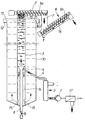
- the water or sludge subjected to a purification treatment is delivered through a coarse matter separator 17 and supplied by a pump 1 through an electrolytic cell 2 into a separating pipe 3.
- the cell 2 is provided e.g. with iron electrodes for passing therebetween the water or sludge to be treated.
- the electrodes are supplied with a direct current, the cell being subjected e.g. to the following reactions: 2H 2 O ⁇ 2OH - + 2H + + 2e - ⁇ H 2 ⁇ Fe 2+ + 2OH - ⁇ Fe(OH) 2 ⁇ Fe 3+ + 3OH - ⁇ Fe(OH) 3 ⁇
- the developing hydrogen gas adheres to ferro- and ferrihydroxide deposits, which are in turn producing a web or mesh structure for trapping solid impurities. This way, the solid matter flocculates and the flock-adhered hydrogen gas makes the flock lighter than water.
- the iron electrodes can be replaced with other metal electrodes as well.
- the electrolysis may produce other gases as well depending on a liquid to be treated.
- the supply pipe 4 opens into a cone 5 included in the separating pipe 3 and provided at its bottom end with a pipe 6 for collecting and removing heavy objects, such as small rocks.
- the flock particles begin to rise from the cone 5 upwards in the pipe 3 at quite a high climbing speed.
- the flock particles pack into a froth-like flock deposit which is forced by a conveyor screw 9a into a flock discharge pipe 7.
- the pipe 7 carries the flock to a solids separator 8, such as e.g. a filter web, a screw press, a separator, a centrifuge or a like.
- the separator 8 includes a chute-like filter web 16 and a conveyor screw 9b on top of it.
- the solid matter can be carried e.g. to a composter and the liquid can be returned back to the intake side of the pump 1.
- the separating pipe 3 extends also downwards from the cone 5 and, thus, it can be fitted with a sand filter 14.
- the treated water has a passage through ports 15 into a receiving and discharge tank 10 having a surface area which is multiple compared to that of the separating pipe 3.
- the climbing speed of water in the separating pipe 3 decelerates in relation to the flock climbing speed for a further improved separation efficiency.
- the tank 10 may simultaneously serve as a storage bin for a liquid to be treated.
- the height difference between the overflow edge 11 and a flock discharge edge 13 included in the receiving and discharge tank 10 can be made adjustable e.g. by providing the pipe 3 with a telescopic top end. By adjusting the top end of the pipe 3 (and the pipe 7) downwards it is possible to receive wetter flock more quickly.
- the overflow edge 11 must be located slightly below the level of the flock discharge edge 13 but a substantial distance above the inlet of the supply pipe 4. Since the pipes 10 and 3 operate on the principle of communicating vessels, the height difference therebetween must be adjusted or balanced in such a manner that both experience overflow and the height difference is caused or determined by the fact that the flock contained in said separating pipe 3 is lighter than water as a result of the hydrogen gas adhered thereto.
- the overflow equilibrium for communicating vessels is achieved by means of vessels having different heights.
- the top end of the separating pipe 3 can be provided with a duct for the discharge of hydrogen gas.
- the hydrogen gas can be recovered. It is also possible to recycle the hydrogen gas back into the separating pipe 3 below the cone 5.
- the invention can be exploited both in a small and a large scale operation.
- the possible large-scale applications include both industrial waste waters and community sewage.
- the possible smaller scale applications include e.g. agricultural farms.
- the invention has already been practically tested in the purification treatment of liquid manure in a hog farm. Hence, it was found out that the great length of separating pipe 3 in relation to the diameter is a particularly critical factor in view of securing a sufficient climbing speed and separation efficiency. In addition, the large surface area of tank 10 in relation to the surface area of pipe 3 was found advantageous in that water separates effectively from flock instead of pursuing to rise into the flock discharge pipe 7.
Landscapes
- Engineering & Computer Science (AREA)
- Life Sciences & Earth Sciences (AREA)
- Biotechnology (AREA)
- Environmental & Geological Engineering (AREA)
- Water Supply & Treatment (AREA)
- Chemical & Material Sciences (AREA)
- Organic Chemistry (AREA)
- Electrochemistry (AREA)
- General Chemical & Material Sciences (AREA)
- Hydrology & Water Resources (AREA)
- Chemical Kinetics & Catalysis (AREA)
- Fish Paste Products (AREA)
- Water Treatment By Electricity Or Magnetism (AREA)
- Separation Of Suspended Particles By Flocculating Agents (AREA)
- Electrolytic Production Of Non-Metals, Compounds, Apparatuses Therefor (AREA)
- Combined Means For Separation Of Solids (AREA)
- Processing And Handling Of Plastics And Other Materials For Molding In General (AREA)
- Filtration Of Liquid (AREA)
- Centrifugal Separators (AREA)
- Glass Compositions (AREA)
Claims (6)
- Eine Abscheidevorrichtung für Flockmasse zur Verwendung bei der Behandlung von Abwasser oder Faulschlamm, umfassend eine Elektrolysezelle (2) und einen Abscheidebehälter (3), in den die in der Elektrolysezelle entwickelte Flockmasse geliefert wird, und in dem die Flockmasse durch die Einwirkung eines bei der Elektrolyse entwickelten Gases nach oben steigt, dadurch gekennzeichnet, daß der Abscheidebehälter (3) ein im wesentlichen vertikales Rohr ist, das von der Elektrolysezelle (2) getrennt ist und einen Durchmesser im Bereich von 100 - 500 mm und eine Länge im Bereich von 2000 - 10 000 mm aufweist, wodurch die Länge wenigstens das 10-fache, vorzugsweise wenigstens das 15-fache des Durchmessers beträgt, und daß ein sich von der Elektrolysezelle (2) zu dem Abscheiderohr (3) erstreckendes Zuführrohr (4) unterhalb des Mittelpunktes des Abscheiderohrs (3) mündet, wobei das Abscheiderohr (3) in Durchflußverbindung mit einem Aufnahme- und Abführbehälter (10) für aufbereitetes Wasser steht und sein oberes Ende über das Oberflächenniveau (11) des Aufnahme- und Abführbehälters (10) ansteigt und mit einem im wesentlichen horizontalen, mit einem Förderer (9a) versehenen Flockmasseabführrohr (7) verbunden ist, wobei das Flockmasseabführrohr (7) mit einem Feststoffabscheider (8) zum Entfernen von Flüssigkeit aus der Flockmasse verbunden ist.
- Vorrichtung nach Anspruch 1, dadurch gekennzeichnet, daß das Zuführrohr (4) in das untere Ende des Abscheiderohrs (3) oder in eine Stelle längs des Abscheiderohrs (3) mündet, dessen Abstand vom unteren Ende des Abscheiderohrs (3) annähernd 1/2 - 1/8 der Länge des Abscheiderohrs (3) beträgt, und daß das obere Ende des Abscheiderohrs (3) eine regulierbare Höhe aufweist, und auf einem höheren Niveau als das Oberflächenniveau (11) in dem Aufnahme- und Abführbehälter angeordnet ist.
- Vorrichtung nach Anspruch 1 oder 2, dadurch gekennzeichnet, daß der Aufnahme- und Abführbehälter (10) für das aufbereitete Wasser den Abscheidebehälter (3) umgibt und eine Oberfläche aufweist, die wesentlich größer als die Querschnittsfläche des Abscheiderohrs (3) ist.
- Vorrichtung nach einem der Ansprüche 1 - 3, dadurch gekennzeichnet, daß das Abscheiderohr (3) an seinem unteren Ende mit einem Sandfilter (14) ausgestattet ist.
- Vorrichtung nach einem der Ansprüche 1 - 4, dadurch gekennzeichnet, daß das Zuführrohr (4) mit einem in dem Abscheiderohr (3) enthaltenen Kegel (5) verbunden ist, wobei das Bodenteil des Kegels in ein Abführrohr (6) für schwere Gegenstände mündet.
- Vorrichtung nach Anspruch 1, dadurch gekennzeichnet, daß das unterhalb der Mündungsstelle des Zuführrohrs (4) angeordnete Abschnitt des Abscheiderohrs (3) aus einer Filtertuchmuffe oder einem Filtersack ausgebildet ist.
Applications Claiming Priority (1)
| Application Number | Priority Date | Filing Date | Title |
|---|---|---|---|
| PCT/FI1994/000518 WO1996015989A1 (en) | 1994-11-18 | 1994-11-18 | Flock separating apparatus |
Publications (2)
| Publication Number | Publication Date |
|---|---|
| EP0794926A1 EP0794926A1 (de) | 1997-09-17 |
| EP0794926B1 true EP0794926B1 (de) | 2000-03-15 |
Family
ID=8556593
Family Applications (1)
| Application Number | Title | Priority Date | Filing Date |
|---|---|---|---|
| EP95900780A Expired - Lifetime EP0794926B1 (de) | 1994-11-18 | 1994-11-18 | Vorrichtung zum trennen von flock |
Country Status (9)
| Country | Link |
|---|---|
| US (1) | US5888359A (de) |
| EP (1) | EP0794926B1 (de) |
| AT (1) | ATE190590T1 (de) |
| AU (1) | AU688410B2 (de) |
| DE (1) | DE69423524T2 (de) |
| DK (1) | DK0794926T3 (de) |
| ES (1) | ES2146304T3 (de) |
| NO (1) | NO317206B1 (de) |
| WO (1) | WO1996015989A1 (de) |
Cited By (1)
| Publication number | Priority date | Publication date | Assignee | Title |
|---|---|---|---|---|
| WO2026032504A1 (en) * | 2024-08-08 | 2026-02-12 | Applied Physics Instruments Api Oy | A method and a system for recovering nutrients from wet animal manure |
Families Citing this family (9)
| Publication number | Priority date | Publication date | Assignee | Title |
|---|---|---|---|---|
| FI111355B (fi) | 1999-03-17 | 2003-07-15 | Metso Paper Inc | Menetelmä ja laite rainan rullauksessa |
| FI115904B (fi) | 2002-01-25 | 2005-08-15 | Bcde Group Waste Man Ltd Oy | Menetelmä ja laite epäpuhtauksien poistamiseksi jätevedestä elektroflotaatiolla |
| FI20020168L (fi) * | 2002-01-30 | 2003-07-31 | Bcde Group Waste Man Ltd Oy | Menetelmä ja laite sekajätteen käsittelemiseksi pyrolyysilla |
| ES2272182B1 (es) * | 2005-10-03 | 2008-03-01 | Novoltec Automatizacion, S.A. | Procedimiento de depuracion de los residuos de la fabricacion de aceite de oliva. |
| FI123310B (fi) * | 2009-08-14 | 2013-02-15 | Hannu Suominen | Menetelmä ja laite rikkivetyä sisältävien vesiliuosten puhdistamiseksi |
| FI123434B (fi) * | 2009-08-26 | 2013-04-30 | Hannu Suominen | Menetelmä ja laite jäteveden puhdistamiseksi |
| SE539404C2 (en) | 2015-10-08 | 2017-09-12 | Axolot Solutions Ab | Electroflotation apparatus having an outlet pipe with a low turbulence orifice |
| BE1026047B1 (nl) | 2018-08-28 | 2019-09-24 | Noah Water Solutions bvba | Methode en inrichting voor het reinigen van de elektrode cellen die gebruikt wordt voor het verwijderen van verontreinigingen uit afvalwater door middel van elektrocoagulatie |
| BE1029516B1 (nl) | 2021-06-21 | 2023-01-23 | Noah Water Solutions bvba | Methode voor het behandelen van zwart water |
Family Cites Families (3)
| Publication number | Priority date | Publication date | Assignee | Title |
|---|---|---|---|---|
| US1099396A (en) * | 1913-09-18 | 1914-06-09 | Colorado Iron Works Co | Apparatus for thickening pulps. |
| DE3643931A1 (de) * | 1986-12-22 | 1988-07-07 | Kernforschungsanlage Juelich | Begasungs/flotationsreaktor |
| WO1993004003A1 (de) * | 1991-08-14 | 1993-03-04 | Iwatech Konradt Gmbh | Verfahren und vorrichtung zum aufbereiten von verunreinigten flüssigkeiten |
-
1994
- 1994-11-18 AU AU81459/94A patent/AU688410B2/en not_active Ceased
- 1994-11-18 US US08/836,849 patent/US5888359A/en not_active Expired - Lifetime
- 1994-11-18 DK DK95900780T patent/DK0794926T3/da active
- 1994-11-18 DE DE69423524T patent/DE69423524T2/de not_active Expired - Fee Related
- 1994-11-18 WO PCT/FI1994/000518 patent/WO1996015989A1/en not_active Ceased
- 1994-11-18 EP EP95900780A patent/EP0794926B1/de not_active Expired - Lifetime
- 1994-11-18 ES ES95900780T patent/ES2146304T3/es not_active Expired - Lifetime
- 1994-11-18 AT AT95900780T patent/ATE190590T1/de active
-
1997
- 1997-05-14 NO NO972229A patent/NO317206B1/no not_active Application Discontinuation
Cited By (1)
| Publication number | Priority date | Publication date | Assignee | Title |
|---|---|---|---|---|
| WO2026032504A1 (en) * | 2024-08-08 | 2026-02-12 | Applied Physics Instruments Api Oy | A method and a system for recovering nutrients from wet animal manure |
Also Published As
| Publication number | Publication date |
|---|---|
| AU688410B2 (en) | 1998-03-12 |
| US5888359A (en) | 1999-03-30 |
| AU8145994A (en) | 1996-06-17 |
| DK0794926T3 (da) | 2000-08-21 |
| ES2146304T3 (es) | 2000-08-01 |
| DE69423524T2 (de) | 2000-10-19 |
| NO972229D0 (no) | 1997-05-14 |
| NO317206B1 (no) | 2004-09-20 |
| ATE190590T1 (de) | 2000-04-15 |
| EP0794926A1 (de) | 1997-09-17 |
| WO1996015989A1 (en) | 1996-05-30 |
| NO972229L (no) | 1997-07-15 |
| DE69423524D1 (de) | 2000-04-20 |
Similar Documents
| Publication | Publication Date | Title |
|---|---|---|
| US4673494A (en) | Water treatment apparatus | |
| US5888359A (en) | Flock separating apparatus | |
| KR20200088943A (ko) | 각종 준설토용 정화시스템 | |
| CN1109846A (zh) | 水的生物纯化过程及其装置 | |
| GB1592609A (en) | Sludge thickening apparatus and process | |
| US6086732A (en) | Flock separating apparatus | |
| WO2011139225A1 (en) | A method and plant for purifying raw water | |
| KR101590037B1 (ko) | 모듈식 수저퇴적물 정화처리 시스템 및 공법 | |
| CN205328738U (zh) | 一种用于污水处理的气浮机 | |
| CN208562084U (zh) | 一种集成式污水处理装置 | |
| WO1998031634A1 (en) | Method and apparatus for purifying a liquid by means of flotation | |
| EP0211451A1 (de) | Verfahren und Anlage zur anaerobischen Reinigung von Abwasser | |
| KR100724778B1 (ko) | 오폐수처리장치 | |
| CN214457211U (zh) | 一种污水回收装置 | |
| KR100687697B1 (ko) | 침전조가 없는 오폐수처리장치 | |
| RU1787949C (ru) | Электрокоагул тор | |
| SU829589A1 (ru) | Метантенк | |
| CN207845205U (zh) | 污水加压气浮装置 | |
| JP3105799B2 (ja) | 固液分離方法および可搬式固液分離装置 | |
| SU966030A1 (ru) | Устройство дл удалени взвешенных веществ из сточных вод | |
| CN107879410A (zh) | 用于污水加压气浮用的加压器机构 | |
| CN107814425A (zh) | 污水加压气浮装置 | |
| SU1730044A2 (ru) | Установка дл очистки сточных вод | |
| RU54934U1 (ru) | Устройство для флотационной очистки природных и сточных вод | |
| SU1139709A1 (ru) | Флотационный классификатор |
Legal Events
| Date | Code | Title | Description |
|---|---|---|---|
| PUAI | Public reference made under article 153(3) epc to a published international application that has entered the european phase |
Free format text: ORIGINAL CODE: 0009012 |
|
| 17P | Request for examination filed |
Effective date: 19970616 |
|
| AK | Designated contracting states |
Kind code of ref document: A1 Designated state(s): AT BE CH DE DK ES FR GB GR IE IT LI NL PT SE |
|
| AX | Request for extension of the european patent |
Free format text: LT PAYMENT 970616 |
|
| GRAG | Despatch of communication of intention to grant |
Free format text: ORIGINAL CODE: EPIDOS AGRA |
|
| 17Q | First examination report despatched |
Effective date: 19981109 |
|
| GRAG | Despatch of communication of intention to grant |
Free format text: ORIGINAL CODE: EPIDOS AGRA |
|
| GRAG | Despatch of communication of intention to grant |
Free format text: ORIGINAL CODE: EPIDOS AGRA |
|
| GRAH | Despatch of communication of intention to grant a patent |
Free format text: ORIGINAL CODE: EPIDOS IGRA |
|
| RAP1 | Party data changed (applicant data changed or rights of an application transferred) |
Owner name: BCDE GROUP WASTE MANAGEMENT LTD OY |
|
| GRAH | Despatch of communication of intention to grant a patent |
Free format text: ORIGINAL CODE: EPIDOS IGRA |
|
| GRAA | (expected) grant |
Free format text: ORIGINAL CODE: 0009210 |
|
| AK | Designated contracting states |
Kind code of ref document: B1 Designated state(s): AT BE CH DE DK ES FR GB GR IE IT LI NL PT SE |
|
| AX | Request for extension of the european patent |
Free format text: LT PAYMENT 19970616 |
|
| LTIE | Lt: invalidation of european patent or patent extension | ||
| PG25 | Lapsed in a contracting state [announced via postgrant information from national office to epo] |
Ref country code: SE Free format text: THE PATENT HAS BEEN ANNULLED BY A DECISION OF A NATIONAL AUTHORITY Effective date: 20000315 Ref country code: LI Free format text: LAPSE BECAUSE OF NON-PAYMENT OF DUE FEES Effective date: 20000315 Ref country code: IT Free format text: LAPSE BECAUSE OF FAILURE TO SUBMIT A TRANSLATION OF THE DESCRIPTION OR TO PAY THE FEE WITHIN THE PRE;WARNING: LAPSES OF ITALIAN PATENTS WITH EFFECTIVE DATE BEFORE 2007 MAY HAVE OCCURRED AT ANY TIME BEFORE 2007. THE CORRECT EFFECTIVE DATE MAY BE DIFFERENT FROM THE ONE RECORDED.SCRIBED TIME-LIMIT Effective date: 20000315 Ref country code: GR Free format text: LAPSE BECAUSE OF NON-PAYMENT OF DUE FEES Effective date: 20000315 Ref country code: CH Free format text: LAPSE BECAUSE OF NON-PAYMENT OF DUE FEES Effective date: 20000315 Ref country code: BE Free format text: LAPSE BECAUSE OF FAILURE TO SUBMIT A TRANSLATION OF THE DESCRIPTION OR TO PAY THE FEE WITHIN THE PRESCRIBED TIME-LIMIT Effective date: 20000315 Ref country code: AT Free format text: LAPSE BECAUSE OF FAILURE TO SUBMIT A TRANSLATION OF THE DESCRIPTION OR TO PAY THE FEE WITHIN THE PRESCRIBED TIME-LIMIT Effective date: 20000315 |
|
| REF | Corresponds to: |
Ref document number: 190590 Country of ref document: AT Date of ref document: 20000415 Kind code of ref document: T |
|
| REG | Reference to a national code |
Ref country code: CH Ref legal event code: EP |
|
| REF | Corresponds to: |
Ref document number: 69423524 Country of ref document: DE Date of ref document: 20000420 |
|
| REG | Reference to a national code |
Ref country code: IE Ref legal event code: FG4D |
|
| PG25 | Lapsed in a contracting state [announced via postgrant information from national office to epo] |
Ref country code: PT Free format text: LAPSE BECAUSE OF FAILURE TO SUBMIT A TRANSLATION OF THE DESCRIPTION OR TO PAY THE FEE WITHIN THE PRESCRIBED TIME-LIMIT Effective date: 20000615 |
|
| ET | Fr: translation filed | ||
| REG | Reference to a national code |
Ref country code: ES Ref legal event code: FG2A Ref document number: 2146304 Country of ref document: ES Kind code of ref document: T3 |
|
| REG | Reference to a national code |
Ref country code: DK Ref legal event code: T3 |
|
| REG | Reference to a national code |
Ref country code: CH Ref legal event code: PL |
|
| PG25 | Lapsed in a contracting state [announced via postgrant information from national office to epo] |
Ref country code: IE Free format text: LAPSE BECAUSE OF NON-PAYMENT OF DUE FEES Effective date: 20001120 |
|
| PLBE | No opposition filed within time limit |
Free format text: ORIGINAL CODE: 0009261 |
|
| STAA | Information on the status of an ep patent application or granted ep patent |
Free format text: STATUS: NO OPPOSITION FILED WITHIN TIME LIMIT |
|
| 26N | No opposition filed | ||
| REG | Reference to a national code |
Ref country code: IE Ref legal event code: MM4A |
|
| REG | Reference to a national code |
Ref country code: GB Ref legal event code: IF02 |
|
| PGFP | Annual fee paid to national office [announced via postgrant information from national office to epo] |
Ref country code: DK Payment date: 20040123 Year of fee payment: 10 |
|
| PGFP | Annual fee paid to national office [announced via postgrant information from national office to epo] |
Ref country code: FR Payment date: 20040311 Year of fee payment: 10 |
|
| PGFP | Annual fee paid to national office [announced via postgrant information from national office to epo] |
Ref country code: NL Payment date: 20040316 Year of fee payment: 10 Ref country code: GB Payment date: 20040316 Year of fee payment: 10 |
|
| PGFP | Annual fee paid to national office [announced via postgrant information from national office to epo] |
Ref country code: DE Payment date: 20040330 Year of fee payment: 10 |
|
| PGFP | Annual fee paid to national office [announced via postgrant information from national office to epo] |
Ref country code: ES Payment date: 20040415 Year of fee payment: 10 |
|
| PG25 | Lapsed in a contracting state [announced via postgrant information from national office to epo] |
Ref country code: GB Free format text: LAPSE BECAUSE OF NON-PAYMENT OF DUE FEES Effective date: 20041118 |
|
| PG25 | Lapsed in a contracting state [announced via postgrant information from national office to epo] |
Ref country code: ES Free format text: LAPSE BECAUSE OF NON-PAYMENT OF DUE FEES Effective date: 20041119 |
|
| PG25 | Lapsed in a contracting state [announced via postgrant information from national office to epo] |
Ref country code: DK Free format text: LAPSE BECAUSE OF NON-PAYMENT OF DUE FEES Effective date: 20041130 |
|
| PG25 | Lapsed in a contracting state [announced via postgrant information from national office to epo] |
Ref country code: NL Free format text: LAPSE BECAUSE OF NON-PAYMENT OF DUE FEES Effective date: 20050601 Ref country code: DE Free format text: LAPSE BECAUSE OF NON-PAYMENT OF DUE FEES Effective date: 20050601 |
|
| REG | Reference to a national code |
Ref country code: DK Ref legal event code: EBP |
|
| GBPC | Gb: european patent ceased through non-payment of renewal fee |
Effective date: 20041118 |
|
| PG25 | Lapsed in a contracting state [announced via postgrant information from national office to epo] |
Ref country code: FR Free format text: LAPSE BECAUSE OF NON-PAYMENT OF DUE FEES Effective date: 20050729 |
|
| NLV4 | Nl: lapsed or anulled due to non-payment of the annual fee |
Effective date: 20050601 |
|
| REG | Reference to a national code |
Ref country code: FR Ref legal event code: ST |
|
| REG | Reference to a national code |
Ref country code: ES Ref legal event code: FD2A Effective date: 20041119 |