EP0795355A2 - Nebenleitung einer Umlaufanlage - Google Patents
Nebenleitung einer Umlaufanlage Download PDFInfo
- Publication number
- EP0795355A2 EP0795355A2 EP96309530A EP96309530A EP0795355A2 EP 0795355 A2 EP0795355 A2 EP 0795355A2 EP 96309530 A EP96309530 A EP 96309530A EP 96309530 A EP96309530 A EP 96309530A EP 0795355 A2 EP0795355 A2 EP 0795355A2
- Authority
- EP
- European Patent Office
- Prior art keywords
- pump
- circulation
- circulation system
- flow
- application device
- Prior art date
- Legal status (The legal status is an assumption and is not a legal conclusion. Google has not performed a legal analysis and makes no representation as to the accuracy of the status listed.)
- Withdrawn
Links
Images


Classifications
-
- B—PERFORMING OPERATIONS; TRANSPORTING
- B05—SPRAYING OR ATOMISING IN GENERAL; APPLYING FLUENT MATERIALS TO SURFACES, IN GENERAL
- B05B—SPRAYING APPARATUS; ATOMISING APPARATUS; NOZZLES
- B05B9/00—Spraying apparatus for discharge of liquids or other fluent material, without essentially mixing with gas or vapour
- B05B9/03—Spraying apparatus for discharge of liquids or other fluent material, without essentially mixing with gas or vapour characterised by means for supplying liquid or other fluent material
- B05B9/04—Spraying apparatus for discharge of liquids or other fluent material, without essentially mixing with gas or vapour characterised by means for supplying liquid or other fluent material with pressurised or compressible container; with pump
- B05B9/043—Spraying apparatus for discharge of liquids or other fluent material, without essentially mixing with gas or vapour characterised by means for supplying liquid or other fluent material with pressurised or compressible container; with pump having pump readily separable from container
-
- B—PERFORMING OPERATIONS; TRANSPORTING
- B05—SPRAYING OR ATOMISING IN GENERAL; APPLYING FLUENT MATERIALS TO SURFACES, IN GENERAL
- B05B—SPRAYING APPARATUS; ATOMISING APPARATUS; NOZZLES
- B05B9/00—Spraying apparatus for discharge of liquids or other fluent material, without essentially mixing with gas or vapour
- B05B9/03—Spraying apparatus for discharge of liquids or other fluent material, without essentially mixing with gas or vapour characterised by means for supplying liquid or other fluent material
- B05B9/04—Spraying apparatus for discharge of liquids or other fluent material, without essentially mixing with gas or vapour characterised by means for supplying liquid or other fluent material with pressurised or compressible container; with pump
- B05B9/0403—Spraying apparatus for discharge of liquids or other fluent material, without essentially mixing with gas or vapour characterised by means for supplying liquid or other fluent material with pressurised or compressible container; with pump with pumps for liquids or other fluent material
- B05B9/0406—Spraying apparatus for discharge of liquids or other fluent material, without essentially mixing with gas or vapour characterised by means for supplying liquid or other fluent material with pressurised or compressible container; with pump with pumps for liquids or other fluent material with several pumps
-
- B—PERFORMING OPERATIONS; TRANSPORTING
- B05—SPRAYING OR ATOMISING IN GENERAL; APPLYING FLUENT MATERIALS TO SURFACES, IN GENERAL
- B05B—SPRAYING APPARATUS; ATOMISING APPARATUS; NOZZLES
- B05B9/00—Spraying apparatus for discharge of liquids or other fluent material, without essentially mixing with gas or vapour
- B05B9/03—Spraying apparatus for discharge of liquids or other fluent material, without essentially mixing with gas or vapour characterised by means for supplying liquid or other fluent material
- B05B9/04—Spraying apparatus for discharge of liquids or other fluent material, without essentially mixing with gas or vapour characterised by means for supplying liquid or other fluent material with pressurised or compressible container; with pump
- B05B9/0403—Spraying apparatus for discharge of liquids or other fluent material, without essentially mixing with gas or vapour characterised by means for supplying liquid or other fluent material with pressurised or compressible container; with pump with pumps for liquids or other fluent material
- B05B9/0413—Spraying apparatus for discharge of liquids or other fluent material, without essentially mixing with gas or vapour characterised by means for supplying liquid or other fluent material with pressurised or compressible container; with pump with pumps for liquids or other fluent material with reciprocating pumps, e.g. membrane pump, piston pump, bellow pump
-
- B—PERFORMING OPERATIONS; TRANSPORTING
- B05—SPRAYING OR ATOMISING IN GENERAL; APPLYING FLUENT MATERIALS TO SURFACES, IN GENERAL
- B05B—SPRAYING APPARATUS; ATOMISING APPARATUS; NOZZLES
- B05B9/00—Spraying apparatus for discharge of liquids or other fluent material, without essentially mixing with gas or vapour
- B05B9/03—Spraying apparatus for discharge of liquids or other fluent material, without essentially mixing with gas or vapour characterised by means for supplying liquid or other fluent material
- B05B9/04—Spraying apparatus for discharge of liquids or other fluent material, without essentially mixing with gas or vapour characterised by means for supplying liquid or other fluent material with pressurised or compressible container; with pump
- B05B9/0403—Spraying apparatus for discharge of liquids or other fluent material, without essentially mixing with gas or vapour characterised by means for supplying liquid or other fluent material with pressurised or compressible container; with pump with pumps for liquids or other fluent material
- B05B9/0423—Spraying apparatus for discharge of liquids or other fluent material, without essentially mixing with gas or vapour characterised by means for supplying liquid or other fluent material with pressurised or compressible container; with pump with pumps for liquids or other fluent material for supplying liquid or other fluent material to several spraying apparatus
Definitions
- Circulation systems for paints and other materials have been used for many years.
- Various one, two and three pipe systems have been utilised with each having its own benefits and problems.
- the simplest system is traditionally a one pipe system.
- such system generally has suffered from the fact that the so-called drops where spray guns or other dispensing stations are located do not have circulation down to the dispensing device with the result that the fluid within the drop tends to settle out and separate with the resultant quality problems when that fluid is later attempted to be dispensed.
- One way of providing circulation in such a system is to provide a return line from the gun or other device.
- a system provides a substantial increase in plumbing (and cost) depending upon the size of the facility and the number of drops.
- this function is accomplished by providing a small electromagnetically driven two-ball reciprocating pump.
- This pump is seal-less and totally enclosed and thus is not capable of leaking upon seal failure.
- Such a pump is essentially a booster pump, that is, if the pressure in the circulation line is 200 psi, this pump boosts the pressure at the outlet of the drop loop by 30 psi or so and thus is capable of injecting paint back into the main circulating loop.
- the device maintains flow in the station drop and has a timed electrical controller which actuates an electromagnetic coil which moves the magnetic shuttle valve and forces paint to circulate through the paint station piping.
- the ball checks ensure that paint is pumped only in the correct direction.
- the shuttle pump in the preferred embodiment pumps in one direction and is electromagnetically returned in the other direction although gravity or springs may also be utilised for the return function.
- the flow rate may be controlled by a timed electrical controller.
- an air operated double diaphragm pump may be used as a station pump.
- a colour change valve such as that manufactured by Graco Inc., applicant of this application, may be used to control flow from the drop loop to the application device.
- a single diaphragm pump forming two chambers may be operated by an external reciprocator such as an air motor manufactured by Graco Inc.
- an embodiment may use a rotary air motor magnetically coupled (to remove the need for seals) to a gear pump.
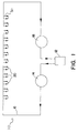
- the system of the instant invention is generally designated 10 and is comprised of a material tank 12 having connected thereto a pump 14 which circulates paint or other fluid through a main circulation pipe 16 which leads to a back pressure regulator 18 which is in turn connected back to tank 12.
- a plurality of drops 20 are provided along the main circulation loop.
- each drop 20 has an inlet line 22 leading to a regulator 24 which is connected to a application device 26 such as a spray gun.
- the downstream side 27 of regulator 24 leads to a bail valve 28 and thence to shuttle valve 30 which is also connected on its downstream side via a bail valve 29 to the main circulation loop 16.
- the shuttle valve or station pump 30 is provided with an inlet 32 thereof and an outlet 34 in a main housing 36.
- Shuttle 38 is formed of stainless steel (as are all wetted parts) and slides in a stainless steel inner sleeve 40. It has located at the outlet 34 thereof an outlet check 42 while adjacent inlet 32 is inlet check 44.
- Shuttle 38 has a pair of annular magnets 46 which are confined by an inner ring of carbon steel 48.
- a plurality of electromagnets 50 are located in housing 36 and separated by carbon steel rings 52. As electromagnets 50 are successively energised, shuttle 38 reciprocates from one end to the other of housing 36. Electromagnets 50 are connected to control electronics 60 which are conventional in nature.
- the electromagnets 50 are energised and shuttle 38 moves downwardly thereby closing outlet check 42 and forcing the paint in outlet chamber 54 out of outlet 34 while at the same time pulling open inlet check 44 and allowing inlet chamber 56 to be filled.
- shuttle 38 moves upwardly thereby closing inlet check 44 and allowing outlet check 42 to open thereby allowing the paint or other fluid to flow from inlet chamber 56 to outlet chamber 54 through interior passage 58.
- Figure 4 shows a colour change valve 60 in the drop loop. Several of these may be added to provide colour change capability.
- FIGS 5 and 6 show an alternate embodiment using an air operated double diaphragm pump 102.
- This uses a conventional air operated double diaphragm pump which has the bail checks 104 removed from the side leading to the application device as shown.
- the air operated double diaphragm pump has first and second fluid chambers, said first chamber receiving flow from said circulation loop and outputting flow to said application device and said second chamber receiving flow from said application device and outputting flow to said circulation loop.
- Figure 7 shows an alternate embodiment using an air operated two chamber single diaphragm pump 202. This is plumbed in the same way as the Figure 5 and 6 embodiment but uses a single diaphragm with an external air motor. This embodiment allows the pump to be pressure balanced as there is little pressure differential across the diaphragm.
- Figure 8 shows an alternate embodiment using an air operated rotary motor magnetically coupled to a gear pump.
Landscapes
- Nozzles (AREA)
- Reciprocating Pumps (AREA)
- Coating Apparatus (AREA)
- Flow Control (AREA)
Applications Claiming Priority (4)
| Application Number | Priority Date | Filing Date | Title |
|---|---|---|---|
| US769975 | 1985-08-27 | ||
| US9302 | 1993-02-10 | ||
| US930295P | 1995-12-29 | 1995-12-29 | |
| US76997596A | 1996-12-19 | 1996-12-19 |
Publications (1)
| Publication Number | Publication Date |
|---|---|
| EP0795355A2 true EP0795355A2 (de) | 1997-09-17 |
Family
ID=26679307
Family Applications (1)
| Application Number | Title | Priority Date | Filing Date |
|---|---|---|---|
| EP96309530A Withdrawn EP0795355A2 (de) | 1995-12-29 | 1996-12-27 | Nebenleitung einer Umlaufanlage |
Country Status (2)
| Country | Link |
|---|---|
| EP (1) | EP0795355A2 (de) |
| JP (1) | JPH09294953A (de) |
Cited By (1)
| Publication number | Priority date | Publication date | Assignee | Title |
|---|---|---|---|---|
| CN107684990A (zh) * | 2017-10-10 | 2018-02-13 | 青海西矿杭萧钢构有限公司 | 一种环保型喷漆设备 |
Families Citing this family (1)
| Publication number | Priority date | Publication date | Assignee | Title |
|---|---|---|---|---|
| JP5979732B2 (ja) | 2014-06-11 | 2016-08-31 | 本田技研工業株式会社 | 塗料循環システム |
-
1996
- 1996-12-27 EP EP96309530A patent/EP0795355A2/de not_active Withdrawn
-
1997
- 1997-01-06 JP JP9000190A patent/JPH09294953A/ja active Pending
Non-Patent Citations (1)
| Title |
|---|
| None |
Cited By (1)
| Publication number | Priority date | Publication date | Assignee | Title |
|---|---|---|---|---|
| CN107684990A (zh) * | 2017-10-10 | 2018-02-13 | 青海西矿杭萧钢构有限公司 | 一种环保型喷漆设备 |
Also Published As
| Publication number | Publication date |
|---|---|
| JPH09294953A (ja) | 1997-11-18 |
Similar Documents
| Publication | Publication Date | Title |
|---|---|---|
| US5634779A (en) | Hydraulic fluid-driven, multicylinder, modular reciprocating piston pump | |
| US6446682B1 (en) | Auto-loading fluid exchanger and method of use | |
| EP1936189B1 (de) | Flüssigkeitspumpe und Brennstoffabgabevorrichtung | |
| US5055013A (en) | Apparatus for injecting fluids | |
| US3018968A (en) | Closed system recirculating assembly | |
| US10480494B2 (en) | Runaway valve system for a pump | |
| EP0254450A3 (en) | Hydraulic paint pump | |
| US3294030A (en) | Positive displacement syrup pump | |
| US5092743A (en) | Pneumatically controlled pump | |
| US5647737A (en) | Reciprocating pump with simplified seal replacement | |
| JPS58113586A (ja) | 多重プランジヤポンプ | |
| US2970546A (en) | Fluid pressure systems | |
| US3394657A (en) | Electro-magnetic, reciprocating pumping mechanism | |
| EP0795355A2 (de) | Nebenleitung einer Umlaufanlage | |
| US4580954A (en) | Oscillating-deflector pump | |
| US3874822A (en) | Electromagnetic plunger pump | |
| US4974673A (en) | System for the production of crude oil by the injection of treatment fluids | |
| US3235129A (en) | Fluid proportioner | |
| GB2283065A (en) | Fluidic pumping system | |
| US11396870B2 (en) | Reciprocating fluid pump including at least one magnet on a spool of a shuttle valve | |
| US3877840A (en) | Electromagnetic plunger pump | |
| US3411673A (en) | Liquid spraying apparatus | |
| JPH05501138A (ja) | パルスレスピストンポンプ | |
| US3269318A (en) | Automatic air injector system | |
| US4189285A (en) | Metering pump |
Legal Events
| Date | Code | Title | Description |
|---|---|---|---|
| PUAI | Public reference made under article 153(3) epc to a published international application that has entered the european phase |
Free format text: ORIGINAL CODE: 0009012 |
|
| AK | Designated contracting states |
Kind code of ref document: A2 Designated state(s): DE FR GB |
|
| STAA | Information on the status of an ep patent application or granted ep patent |
Free format text: STATUS: THE APPLICATION IS DEEMED TO BE WITHDRAWN |
|
| 18D | Application deemed to be withdrawn |
Effective date: 19990701 |