EP0795435A1 - Einstellbare Rücklehne für Fahrzeugsitz - Google Patents
Einstellbare Rücklehne für Fahrzeugsitz Download PDFInfo
- Publication number
- EP0795435A1 EP0795435A1 EP97400369A EP97400369A EP0795435A1 EP 0795435 A1 EP0795435 A1 EP 0795435A1 EP 97400369 A EP97400369 A EP 97400369A EP 97400369 A EP97400369 A EP 97400369A EP 0795435 A1 EP0795435 A1 EP 0795435A1
- Authority
- EP
- European Patent Office
- Prior art keywords
- seat
- backrest
- stop
- lever
- stroke
- Prior art date
- Legal status (The legal status is an assumption and is not a legal conclusion. Google has not performed a legal analysis and makes no representation as to the accuracy of the status listed.)
- Granted
Links
- 238000006073 displacement reaction Methods 0.000 claims abstract description 9
- 230000000694 effects Effects 0.000 claims description 16
- 230000008878 coupling Effects 0.000 claims description 10
- 238000010168 coupling process Methods 0.000 claims description 10
- 238000005859 coupling reaction Methods 0.000 claims description 10
- 230000003014 reinforcing effect Effects 0.000 description 1
Images



Classifications
-
- B—PERFORMING OPERATIONS; TRANSPORTING
- B60—VEHICLES IN GENERAL
- B60N—SEATS SPECIALLY ADAPTED FOR VEHICLES; VEHICLE PASSENGER ACCOMMODATION NOT OTHERWISE PROVIDED FOR
- B60N2/00—Seats specially adapted for vehicles; Arrangement or mounting of seats in vehicles
- B60N2/02—Seats specially adapted for vehicles; Arrangement or mounting of seats in vehicles the seat or part thereof being movable, e.g. adjustable
- B60N2/22—Seats specially adapted for vehicles; Arrangement or mounting of seats in vehicles the seat or part thereof being movable, e.g. adjustable the back-rest being adjustable
-
- B—PERFORMING OPERATIONS; TRANSPORTING
- B60—VEHICLES IN GENERAL
- B60N—SEATS SPECIALLY ADAPTED FOR VEHICLES; VEHICLE PASSENGER ACCOMMODATION NOT OTHERWISE PROVIDED FOR
- B60N2/00—Seats specially adapted for vehicles; Arrangement or mounting of seats in vehicles
- B60N2/02—Seats specially adapted for vehicles; Arrangement or mounting of seats in vehicles the seat or part thereof being movable, e.g. adjustable
- B60N2/20—Seats specially adapted for vehicles; Arrangement or mounting of seats in vehicles the seat or part thereof being movable, e.g. adjustable the back-rest being tiltable, e.g. to permit easy access
Definitions
- the present invention relates to a seat for a motor vehicle provided with a variable position backrest.
- a seat for a motor vehicle of the type comprising a backrest mounted to tilt on a seat by means of an articulation controlled by a rotary member actuable in a first direction of adjustment of the inclination of the backrest with respect to the seat and in a second direction, opposite to the first, of temporary folding of this folder towards the seat, and of the type comprising means for limiting the folding stroke of the folder.
- the means for limiting the folding back stroke maintain the latter in an inclined position relative to the horizontal towards the front of the seat. In this way, an occupant can lean on the folded backrest when accessing the rear seats of the vehicle or when leaving these rear seats.
- a front seat of a motor vehicle is connected to the floor of the vehicle by means of a pair of rails for the longitudinal positioning of this seat.
- Certain types of front seat include means for unlocking the slides, which are actuated automatically under the effect of the backrest being folded towards the seat to allow the seat to be moved forward so as to facilitate access to the rear seats.
- a seat in different configuration of use, for example, a configuration in a current seat, adapted in particular to driving, or else a configuration in tablet.
- This last configuration is obtained, in certain types of seats, by folding the backrest towards the seat so as to place it in a substantially horizontal position.
- the means for limiting the folding down stroke prevent the latter from being placed in a substantially horizontal position and therefore obtaining a tablet configuration.
- the object of the invention is to propose a seat for a motor vehicle provided with a backrest capable of being temporarily folded down towards the seat, the downward travel of this backrest causing in particular the automatic unlocking of the slides and being limited to an inclined position. of the backrest with respect to the horizontal, this without preventing the possibility of placing the backrest in a substantially horizontal position so as to obtain a tablet configuration of the seat.
- the subject of the invention is a seat for a motor vehicle of the aforementioned type, characterized in that the limiting means comprise first stop means connected to the backrest and second stop means connected to the seat, these second means being movable between an active position in which, when the backrest is folded back, they cross the path of the first stop means, and a retracted position in which they are spaced from this path, the seat further comprising means for retracting the seconds stop means actuated under the effect of the displacement of the control member in the direction of adjustment of the inclination of the backrest.
- FIG. 1 shows a front seat 10 according to the invention arranged in the passenger compartment of a motor vehicle.
- the seat 10 comprises a backrest 12 mounted to tilt on a seat 14 by means of a pair of articulations 16, one of which is shown in FIG. 2.
- the front and rear orientations correspond to the usual orientations of an occupant seated in the seat 10.
- the seat 14 is connected to a pair of conventional slides 18 by means of front 20 and rear feet 22. These slides allow the longitudinal positioning of the seat and are connected in a manner known per se to a floor 24 of the passenger compartment. vehicle.
- the joints 16 are of known type described for example in FR-A-2,722,150 (FR-A-94 08 297).
- each articulation 16 comprises two flanges 26, 28 one of which is fixed to a fitting 30 secured to the seat frame 14A and the other is fixed to the frame File 12A.
- the flanges 26, 28 are rotatable with respect to each other.
- the flanges 26, 28 define between them a housing for means for coupling these flanges not shown in the figures. These means are controlled by a member 32 forming an axis pin coinciding with the pivot axis of the backrest.
- control members 32 of the two articulations 16 are coupled together using conventional means 34.
- a control handle 36 common to the two articulations 16, is fixed to the control member 32 illustrated in FIG. 2.
- any reference to an articulation 16 will relate to that illustrated in FIG. 2.
- the control member 32 can be actuated, by rotation about its axis, in two opposite directions, namely a first clockwise direction for adjusting the inclination of the backrest relative to the seat and a second counterclockwise direction of folding temporary from this file to the seat.
- the seat 10 includes means 38 for limiting the backrest folding stroke 12. These means 38 allow, when the control member 32 is actuated in the direction of temporary folding of the backrest (anti-clockwise), to limit the tilting of the backrest 12 to a position I, shown diagrammatically by a dashed line in FIG. 1, in which the backrest is inclined relative to the horizontal towards the front.
- the seat 10 also comprises means 40 for unlocking the slides 18 actuated under the effect of the displacement of the control member 32 in the direction of temporary folding of the backrest (anti-clockwise direction).
- the means 38 and 40 will be described below with reference to FIGS. 2 to 5.
- the means 38 for limiting the folding down stroke of the backrest 12 comprise first abutment means connected to the backrest 12 comprising, for example, a substantially transverse section 42 of a bent rod of the frame 12A of the backrest.
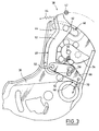
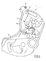
- the means 38 also include second stop means 44 connected to the seat 14, movable between an active position in which, during the folding of the backrest towards the seat, they cross the path of the first stop means 42, as shown in FIGS. 2 and 4, and a retracted position in which they are moved away from this path, as shown in FIG. 5.
- the second stop means 44 are retractable using means 46 actuated under the effect of the displacement of the control member 32 in the direction of adjustment of the inclination of the backrest (clockwise).
- the second stop means 46 comprise a rocker 48 pivotally mounted on the fitting 30 by means of a pivot 50.
- This rocker 48 is provided with a first stop arm 52 which can be moved between an active position in which , when the backrest is folded back, it crosses the path of the first stop means 42, and a retracted position in which it is moved away from this path.
- the means 46 for retracting this abutment arm 52 comprise a cam 54 integral in rotation with the control member 32 cooperating with a cam follower 56 carried by a second operating arm 58 of the rocker, substantially perpendicular to the arm of stop 52.
- the stroke of the stop arm 52 is limited by the ends of a curvilinear buttonhole 60 formed in the fitting 30, in which a end-of-travel finger 62 is guided carried by this stop arm 52.
- the stop arm 52 is resiliently returned to the active position by means of a spring 64 with an angular effect shown diagrammatically in FIG. 3.
- the means 40 for unlocking the slideways 18 comprise a control lever 66 pivotally mounted on the fitting 30 around the same pivot 50 and the same axis as the rocker 48.
- control lever 66 The free end of the control lever 66 is connected to a conventional device for unlocking the slideways (not shown in the figures) by means of a cable 68 of the "Bowden" type housed in a sheath 69.
- the control lever 66 can be moved between a rest position for locking the slides 18 and an active position for unlocking these slides.
- the control lever 66 is resiliently returned to the rest position by a spring 70 urging the cable 68 and shown diagrammatically in FIG. 3.
- the control lever 66 is connected to the operating arm 58 by buttonhole coupling means allowing, on the one hand, an active stroke of the lever 48 in the counterclockwise direction driving the lever 66 towards its position for unlocking the slides , and on the other hand, a dead stroke of the rocker 48 relative to the lever 66, opposite to its active stroke.
- the buttonhole coupling means comprise a buttonhole 72 in which is guided a coupling pin forming the cam follower 56.
- the stop arm 52 and the lever 66 for controlling unlocking of the slides are maintained, respectively, in their active and rest position under the effect of the springs 64 and 70.
- the handle 36 is actuated so as to drive the control member 32 counterclockwise, represented by an arrow in FIG. 4.
- the first abutment means 42 come into contact with the abutment arm 52 and drive it in an anti-clockwise direction until this abutment arm 52 is immobilized by cooperation of the limit switch finger 62 with the front end of the curved buttonhole 60, as shown in FIG. 4.
- the backrest 12 is then maintained in the position I illustrated in FIG. 1.
- the counterclockwise movement of the stop arm 52 corresponds to an active stroke of the rocker 48 causing the lever 66 to be driven in the anti-clockwise direction -time, towards its unlocking position of the slides, as shown in FIG. 4.
- An occupant wishing to access the rear seats of the vehicle or to get out of these rear seats can rest on the folded backrest 12 after pushing the seat 10 forward to increase the clearance allowing access to the rear of the vehicle.
- the handle 36 is actuated in the opposite direction to the previous case, so as to drive the control member 32 in the clockwise direction represented by an arrow in the figure 5.
- the cam 54 is driven clockwise and comes into contact with the cam follower 56 so as to move the lever 48 clockwise until the limit switch 62 is in contact with the rear end of the curved buttonhole 60, as shown in FIG. 5.
- the stop arm 52 is then in the retracted position away from the path of the first stop means 42.
- the handle 36 is released, which causes the articulations 16 to be locked.
- the invention is not limited to the embodiment described above.
- control lever 66 can be omitted, the cable 68 being directly connected to the free end of the operating arm 58.
- the movement in the counterclockwise direction of the operating arm causes traction on the cable 68 and an unlocking of the slides, and the clockwise movement of this maneuvering arm slightly repels the cable 68, which is of no significant consequence when the length of the cable 68 outside the sheath is sufficient.
- the invention has many advantages.
Landscapes
- Engineering & Computer Science (AREA)
- Aviation & Aerospace Engineering (AREA)
- Transportation (AREA)
- Mechanical Engineering (AREA)
- Seats For Vehicles (AREA)
- Chairs For Special Purposes, Such As Reclining Chairs (AREA)
Applications Claiming Priority (2)
| Application Number | Priority Date | Filing Date | Title |
|---|---|---|---|
| FR9603308A FR2746064B1 (fr) | 1996-03-15 | 1996-03-15 | Siege pour vehicule automobile muni d'un dossier a position variable |
| FR9603308 | 1996-03-15 |
Publications (2)
| Publication Number | Publication Date |
|---|---|
| EP0795435A1 true EP0795435A1 (de) | 1997-09-17 |
| EP0795435B1 EP0795435B1 (de) | 1999-10-13 |
Family
ID=9490236
Family Applications (1)
| Application Number | Title | Priority Date | Filing Date |
|---|---|---|---|
| EP19970400369 Expired - Lifetime EP0795435B1 (de) | 1996-03-15 | 1997-02-19 | Einstellbare Rücklehne für Fahrzeugsitz |
Country Status (3)
| Country | Link |
|---|---|
| EP (1) | EP0795435B1 (de) |
| DE (1) | DE69700609T2 (de) |
| FR (1) | FR2746064B1 (de) |
Cited By (1)
| Publication number | Priority date | Publication date | Assignee | Title |
|---|---|---|---|---|
| US7950742B2 (en) | 2008-04-08 | 2011-05-31 | Toyota Boshoku Kabushiki Kaisha | Connecting apparatuses for vehicular seats |
Families Citing this family (6)
| Publication number | Priority date | Publication date | Assignee | Title |
|---|---|---|---|---|
| FR2804386B1 (fr) * | 2000-02-02 | 2002-05-17 | Faure Bertrand Equipements Sa | Siege de vehicule comportant un dossier rabattable vers l'avant |
| FR2830803B1 (fr) | 2001-10-15 | 2004-01-16 | Faurecia Sieges Automobile | Siege de vehicule comportant un dossier rabattable vers l'avant |
| FR2830804B1 (fr) | 2001-10-15 | 2004-01-16 | Faurecia Sieges Automobile | Siege de vehicule comportant un dossier rabattable vers l'avant |
| CA2417003C (en) * | 2002-04-18 | 2007-04-17 | Faurecia Automotive Seating Canada Limited | Improved vehicle seat assembly |
| JP5309746B2 (ja) * | 2008-07-15 | 2013-10-09 | トヨタ紡織株式会社 | 車両用シート |
| FR3071785B1 (fr) * | 2017-10-04 | 2019-09-20 | Psa Automobiles Sa | Structure de siege de vehicule automobile dotee d’une agrafe de maintien d’un carter de recouvrement. |
Citations (3)
| Publication number | Priority date | Publication date | Assignee | Title |
|---|---|---|---|---|
| US3973799A (en) * | 1975-09-18 | 1976-08-10 | General Motors Corporation | Swiveling and folding bench seat |
| EP0628445A1 (de) * | 1993-05-19 | 1994-12-14 | Cesa Compagnie Europeenne De Sieges Pour Automobiles | Mehrfachsitz für Kraftfahrzeuge |
| FR2722150A1 (fr) * | 1994-07-05 | 1996-01-12 | Cesa | Articulation a memoire de position de reglage pour siege |
-
1996
- 1996-03-15 FR FR9603308A patent/FR2746064B1/fr not_active Expired - Fee Related
-
1997
- 1997-02-19 EP EP19970400369 patent/EP0795435B1/de not_active Expired - Lifetime
- 1997-02-19 DE DE1997600609 patent/DE69700609T2/de not_active Expired - Fee Related
Patent Citations (3)
| Publication number | Priority date | Publication date | Assignee | Title |
|---|---|---|---|---|
| US3973799A (en) * | 1975-09-18 | 1976-08-10 | General Motors Corporation | Swiveling and folding bench seat |
| EP0628445A1 (de) * | 1993-05-19 | 1994-12-14 | Cesa Compagnie Europeenne De Sieges Pour Automobiles | Mehrfachsitz für Kraftfahrzeuge |
| FR2722150A1 (fr) * | 1994-07-05 | 1996-01-12 | Cesa | Articulation a memoire de position de reglage pour siege |
Cited By (1)
| Publication number | Priority date | Publication date | Assignee | Title |
|---|---|---|---|---|
| US7950742B2 (en) | 2008-04-08 | 2011-05-31 | Toyota Boshoku Kabushiki Kaisha | Connecting apparatuses for vehicular seats |
Also Published As
| Publication number | Publication date |
|---|---|
| FR2746064A1 (fr) | 1997-09-19 |
| FR2746064B1 (fr) | 1998-06-12 |
| EP0795435B1 (de) | 1999-10-13 |
| DE69700609T2 (de) | 2000-05-31 |
| DE69700609D1 (de) | 1999-11-18 |
Similar Documents
| Publication | Publication Date | Title |
|---|---|---|
| EP0788923A1 (de) | Fahrzeugsitzverriegelung und Sitz mit einem solchen Mechanismus | |
| FR2799420A1 (fr) | Siege de vehicule | |
| FR2795688A1 (fr) | Siege de vehicule equipe d'un mecanisme d'articulation | |
| FR2766139A1 (fr) | Dispositif d'articulation pour siege de vehicule, et siege de vehicule comportant un tel dispositif | |
| EP0559624B1 (de) | Schwenkbetätigungsvorrichtung einer Trittstufenanordnung für Fahrzeuge | |
| FR2771688A1 (fr) | Siege comportant une ceinture de securite integree | |
| FR2481906A1 (fr) | Armature de siege, en particulier pour automobile | |
| FR2838391A1 (fr) | Dispositif de fixation d'un siege sur un plancher de vehicule et siege equipe d'un tel dispositif de fixation | |
| FR2621537A1 (fr) | Siege de vehicule automobile comportant un dossier a inclinaison variable | |
| EP0800952A1 (de) | Kraftfahrzeugsitz, nach vorn bewegbar, um zu einem Hinterraum Zugang zu haben | |
| EP0795435B1 (de) | Einstellbare Rücklehne für Fahrzeugsitz | |
| EP0466534B1 (de) | Handbremshebel, insbesondere für Kraftfahrzeuge | |
| FR2755074A1 (fr) | Dispositif de reglage en hauteur d'un accoudoir et accoudoir de vehicule automobile equipe d'un tel dispositif de reglage | |
| EP0402195B1 (de) | Lösbare Befestigungsvorrichtung für einen Rücksitz eines Kraftfahrzeuges | |
| EP0404628B1 (de) | Sitz mit verstellbarer und umlenkbarer Rückenlehne | |
| EP3619439B1 (de) | Vorrichtung zum einstellen eines kraftfahrzeugsitzbetätigungskabels | |
| FR2459740A1 (fr) | Siege avant rabattable pour vehicule automobile | |
| FR2756230A1 (fr) | Dispositif d'actionnement d'un organe de commande d'un mecanisme de siege de vehicule automobile et siege muni d'un tel dispositif | |
| FR2882537A1 (fr) | Siege de vehicule muni d'un dossier rabattable se debloquant lors du retour en position de l'assise | |
| FR2609948A1 (fr) | Dispositif de verrouillage a inertie pour siege de vehicule | |
| FR2800021A1 (fr) | Siege de vehicule comportant un dossier basculable vers l'avant avec une commande a rattrapage de jeux | |
| EP0631899B1 (de) | Höheneinstellungsvorrichtung für ein Kraftfahrzeug | |
| FR2804386A1 (fr) | Siege de vehicule comportant un dossier rabattable vers l'avant | |
| FR2781436A1 (fr) | Siege pour vehicule automobile a dossier rabattable | |
| FR2868366A1 (fr) | Siege de vehicule, vehicule comportant un tel siege et dispositif de verrouillage pour le dossier d'un tel siege |
Legal Events
| Date | Code | Title | Description |
|---|---|---|---|
| PUAI | Public reference made under article 153(3) epc to a published international application that has entered the european phase |
Free format text: ORIGINAL CODE: 0009012 |
|
| 17P | Request for examination filed |
Effective date: 19970623 |
|
| AK | Designated contracting states |
Kind code of ref document: A1 Designated state(s): BE DE ES GB IT |
|
| GRAG | Despatch of communication of intention to grant |
Free format text: ORIGINAL CODE: EPIDOS AGRA |
|
| GRAG | Despatch of communication of intention to grant |
Free format text: ORIGINAL CODE: EPIDOS AGRA |
|
| GRAH | Despatch of communication of intention to grant a patent |
Free format text: ORIGINAL CODE: EPIDOS IGRA |
|
| 17Q | First examination report despatched |
Effective date: 19990315 |
|
| GRAH | Despatch of communication of intention to grant a patent |
Free format text: ORIGINAL CODE: EPIDOS IGRA |
|
| GRAA | (expected) grant |
Free format text: ORIGINAL CODE: 0009210 |
|
| AK | Designated contracting states |
Kind code of ref document: B1 Designated state(s): BE DE ES GB IT |
|
| PG25 | Lapsed in a contracting state [announced via postgrant information from national office to epo] |
Ref country code: IT Free format text: LAPSE BECAUSE OF FAILURE TO SUBMIT A TRANSLATION OF THE DESCRIPTION OR TO PAY THE FEE WITHIN THE PRESCRIBED TIME-LIMIT;WARNING: LAPSES OF ITALIAN PATENTS WITH EFFECTIVE DATE BEFORE 2007 MAY HAVE OCCURRED AT ANY TIME BEFORE 2007. THE CORRECT EFFECTIVE DATE MAY BE DIFFERENT FROM THE ONE RECORDED. Effective date: 19991013 Ref country code: GB Free format text: LAPSE BECAUSE OF FAILURE TO SUBMIT A TRANSLATION OF THE DESCRIPTION OR TO PAY THE FEE WITHIN THE PRESCRIBED TIME-LIMIT Effective date: 19991013 Ref country code: ES Free format text: THE PATENT HAS BEEN ANNULLED BY A DECISION OF A NATIONAL AUTHORITY Effective date: 19991013 |
|
| REF | Corresponds to: |
Ref document number: 69700609 Country of ref document: DE Date of ref document: 19991118 |
|
| PG25 | Lapsed in a contracting state [announced via postgrant information from national office to epo] |
Ref country code: BE Free format text: LAPSE BECAUSE OF NON-PAYMENT OF DUE FEES Effective date: 20000228 |
|
| GBV | Gb: ep patent (uk) treated as always having been void in accordance with gb section 77(7)/1977 [no translation filed] |
Effective date: 19991013 |
|
| PLBE | No opposition filed within time limit |
Free format text: ORIGINAL CODE: 0009261 |
|
| STAA | Information on the status of an ep patent application or granted ep patent |
Free format text: STATUS: NO OPPOSITION FILED WITHIN TIME LIMIT |
|
| BERE | Be: lapsed |
Owner name: CIE EUROPEENNE DE SIEGES POUR AUTOMOBILES CESA Effective date: 20000228 |
|
| 26N | No opposition filed | ||
| PGFP | Annual fee paid to national office [announced via postgrant information from national office to epo] |
Ref country code: DE Payment date: 20080208 Year of fee payment: 12 |
|
| PG25 | Lapsed in a contracting state [announced via postgrant information from national office to epo] |
Ref country code: DE Free format text: LAPSE BECAUSE OF NON-PAYMENT OF DUE FEES Effective date: 20090901 |