EP0795681B1 - Antriebsvorrichtung für verstellbare Leitschaufeln eines Turbomaschinenkompressors - Google Patents
Antriebsvorrichtung für verstellbare Leitschaufeln eines Turbomaschinenkompressors Download PDFInfo
- Publication number
- EP0795681B1 EP0795681B1 EP97400549A EP97400549A EP0795681B1 EP 0795681 B1 EP0795681 B1 EP 0795681B1 EP 97400549 A EP97400549 A EP 97400549A EP 97400549 A EP97400549 A EP 97400549A EP 0795681 B1 EP0795681 B1 EP 0795681B1
- Authority
- EP
- European Patent Office
- Prior art keywords
- platform
- collector
- pivot pin
- rod
- bore
- Prior art date
- Legal status (The legal status is an assumption and is not a legal conclusion. Google has not performed a legal analysis and makes no representation as to the accuracy of the status listed.)
- Expired - Lifetime
Links
- 238000011144 upstream manufacturing Methods 0.000 claims description 16
- 238000010257 thawing Methods 0.000 claims description 5
- 230000002093 peripheral effect Effects 0.000 claims 2
- 230000000903 blocking effect Effects 0.000 description 1
- 230000000295 complement effect Effects 0.000 description 1
- 238000006073 displacement reaction Methods 0.000 description 1
- 238000007789 sealing Methods 0.000 description 1
- 210000003462 vein Anatomy 0.000 description 1
Images

Classifications
-
- F—MECHANICAL ENGINEERING; LIGHTING; HEATING; WEAPONS; BLASTING
- F01—MACHINES OR ENGINES IN GENERAL; ENGINE PLANTS IN GENERAL; STEAM ENGINES
- F01D—NON-POSITIVE DISPLACEMENT MACHINES OR ENGINES, e.g. STEAM TURBINES
- F01D17/00—Regulating or controlling by varying flow
- F01D17/10—Final actuators
- F01D17/12—Final actuators arranged in stator parts
- F01D17/14—Final actuators arranged in stator parts varying effective cross-sectional area of nozzles or guide conduits
- F01D17/16—Final actuators arranged in stator parts varying effective cross-sectional area of nozzles or guide conduits by means of nozzle vanes
- F01D17/162—Final actuators arranged in stator parts varying effective cross-sectional area of nozzles or guide conduits by means of nozzle vanes for axial flow, i.e. the vanes turning around axes which are essentially perpendicular to the rotor centre line
-
- F—MECHANICAL ENGINEERING; LIGHTING; HEATING; WEAPONS; BLASTING
- F04—POSITIVE - DISPLACEMENT MACHINES FOR LIQUIDS; PUMPS FOR LIQUIDS OR ELASTIC FLUIDS
- F04D—NON-POSITIVE-DISPLACEMENT PUMPS
- F04D29/00—Details, component parts, or accessories
- F04D29/40—Casings; Connections of working fluid
- F04D29/52—Casings; Connections of working fluid for axial pumps
- F04D29/54—Fluid-guiding means, e.g. diffusers
- F04D29/56—Fluid-guiding means, e.g. diffusers adjustable
- F04D29/563—Fluid-guiding means, e.g. diffusers adjustable specially adapted for elastic fluid pumps
-
- F—MECHANICAL ENGINEERING; LIGHTING; HEATING; WEAPONS; BLASTING
- F05—INDEXING SCHEMES RELATING TO ENGINES OR PUMPS IN VARIOUS SUBCLASSES OF CLASSES F01-F04
- F05D—INDEXING SCHEME FOR ASPECTS RELATING TO NON-POSITIVE-DISPLACEMENT MACHINES OR ENGINES, GAS-TURBINES OR JET-PROPULSION PLANTS
- F05D2230/00—Manufacture
- F05D2230/60—Assembly methods
-
- F—MECHANICAL ENGINEERING; LIGHTING; HEATING; WEAPONS; BLASTING
- F05—INDEXING SCHEMES RELATING TO ENGINES OR PUMPS IN VARIOUS SUBCLASSES OF CLASSES F01-F04
- F05D—INDEXING SCHEME FOR ASPECTS RELATING TO NON-POSITIVE-DISPLACEMENT MACHINES OR ENGINES, GAS-TURBINES OR JET-PROPULSION PLANTS
- F05D2240/00—Components
- F05D2240/60—Shafts
- F05D2240/61—Hollow
-
- F—MECHANICAL ENGINEERING; LIGHTING; HEATING; WEAPONS; BLASTING
- F05—INDEXING SCHEMES RELATING TO ENGINES OR PUMPS IN VARIOUS SUBCLASSES OF CLASSES F01-F04
- F05D—INDEXING SCHEME FOR ASPECTS RELATING TO NON-POSITIVE-DISPLACEMENT MACHINES OR ENGINES, GAS-TURBINES OR JET-PROPULSION PLANTS
- F05D2260/00—Function
- F05D2260/20—Heat transfer, e.g. cooling
-
- F—MECHANICAL ENGINEERING; LIGHTING; HEATING; WEAPONS; BLASTING
- F05—INDEXING SCHEMES RELATING TO ENGINES OR PUMPS IN VARIOUS SUBCLASSES OF CLASSES F01-F04
- F05D—INDEXING SCHEME FOR ASPECTS RELATING TO NON-POSITIVE-DISPLACEMENT MACHINES OR ENGINES, GAS-TURBINES OR JET-PROPULSION PLANTS
- F05D2260/00—Function
- F05D2260/50—Kinematic linkage, i.e. transmission of position
-
- F—MECHANICAL ENGINEERING; LIGHTING; HEATING; WEAPONS; BLASTING
- F05—INDEXING SCHEMES RELATING TO ENGINES OR PUMPS IN VARIOUS SUBCLASSES OF CLASSES F01-F04
- F05D—INDEXING SCHEME FOR ASPECTS RELATING TO NON-POSITIVE-DISPLACEMENT MACHINES OR ENGINES, GAS-TURBINES OR JET-PROPULSION PLANTS
- F05D2260/00—Function
- F05D2260/70—Adjusting of angle of incidence or attack of rotating blades
- F05D2260/74—Adjusting of angle of incidence or attack of rotating blades by turning around an axis perpendicular the rotor centre line
Definitions
- the invention relates to a control device for a pivot. integrated in a collector. It applies in particular in the field of aeronautics, turbomachinery having a direct air inlet vane variable timing.
- Certain turbomachinery have guide vanes variable setting to regulate the air flow supplying the compressor stages located downstream.
- the vanes have pivots which extend through a envelope delimiting a flow vein.
- Each pivot is rotated through a link connected to a control mechanism such as a ring whose displacement causes all the links in unison.
- the object of the invention is to solve this problem and to create a pivot control device integrated in a manifold allowing the defrosting of the moving blades and simultaneously ensuring the orientation of the movable blades.
- the control device includes means for fixing and articulation of the pivot mounted in a bore a platform fixed to the collector by upstream flanges and downstream.
- the means of fixing and articulation of the pivot have a hollow friction sleeve with a slot circumferential in which is inserted a first part of a link.
- Control means for the orientation of the movable blades are mounted outside the collector and connected to a second part of the link.
- Corresponding lights are fitted in the collector and into the platform so as to ensure the maneuverability of the variable-timing control device through the link.
- the first part of the rod is inserted into the bore of the platform by manifold and platform lights and has an eye into which the hollow pivot is inserted.
- the lights of collector and platform are arranged opposite the slot in the hollow socket.
- the second part of the link is arranged outside of the collector and connected on the one hand to the first part of the connecting rod and secondly to the control means of the orientation of the movable blades.
- Defrosting of the moving blade is ensured through of the hollow pivot which allows the circulation of hot air between the manifold and the inside of the blades.
- control device for pivot integrated in an air manifold in which the pivot of a movable blade with variable setting is rotated by through a link connected to means of control of the orientation of the movable blade and comprising means of fixing and articulation of the pivot mounted in a bore of a platform fixed to the air collector by upstream and downstream flanges is characterized in that the means of fixing and articulation of the pivot include a socket friction hollow fixed in the bore of the platform, the hollow socket having a circumferential slot in which is inserted a first part of the link.
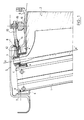
- the air intake of the turbojet engine is provided with fixed arms 1 and guide vanes 2 movable about a radial axis XX 'passing through pivots 3 located at the upper ends movable blades 2.
- the fixed arms 1, the movable vanes 2 and the pivots 3 are hollow so as to allow the circulation of the hot defrost air taken at the outlet of the high pressure compressor not shown.
- the fixed arms 1 and the pivots 3 of the movable vanes 2 are mounted in external platforms 4 brought into contact with each other, and are capped by an air manifold 5 secured to an external ferrule 6.
- the platforms 4 comprise two upstream 7 and downstream 8 side flanges which are fixed to corresponding flanges of the manifold 5 for example by means of a screw and nut system.
- the platforms 4 form with the manifold 5 a toroidal enclosure which receives, contains and distributes the defrosting air from the fixed arms 1 and the moving vanes 2.
- the sealing between the inside and the outside of the manifold is ensured by to the flange-to-flange fastenings between the manifold 5 and the platforms 4.
- Each platform 4 has on its external face, between the two lateral flanges 7,8, a thick transverse region traversed by two bores 9, 10, respectively upstream and downstream oriented radially.
- the fixed arms 1 are embedded and bolted in the first upstream bore 9 of the thickened region of the platform 4.
- the pivots 3 of the movable blades 2 are mounted in the second downstream bore 10 and pivot in this second bore via of a hollow friction sleeve 11 secured to the platform 4.
- the pivoting of the pivots 3 of the movable vanes 2 around the radial axis XX ' is controlled by a rod made up of two parts respectively upstream 12 and downstream 13.
- the upstream parts 12 and downstream 13 are respectively arranged inside and outside the manifold 5.
- the upstream portion 12 is inserted into the bore 10 of the platform 4 by means of lights made respectively in the manifold 5, in the platform 4 and in the hollow friction sleeve 11, the different lights being arranged opposite one another.
- the downstream part 13 is linked by a first end to the upstream part 12 by means of a lock nut blocking 14 and has a second movable end linearly in a ball joint 15 integral with a ring of control and synchronization 16. Control of pivoting of all the moving blades is performed simultaneously by via the control ring in a manner known in oneself.
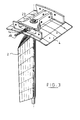
- FIG. 2 represents a perspective and exploded view of the means of fixing and articulation of the pivots of the blades mobile, according to the invention.
- the articulation of the pivot 3 of a movable blade 2 inside the downstream bore 10 of the platform 4 is effected by means of a hollow friction sleeve 11.
- the hollow sleeve comprises, in its upper region, a circumferential slot 20 of predetermined width.
- the hollow socket 11 is put in place and fixed in the downstream bore 10 of the platform 4 so that the slot 20 is disposed opposite the light 21 of the platform 4.
- the upstream part 12 of the link comprises a flat area pierced at its end with an eye 22 of predetermined shape and section, for example in the shape of a square. This flat area is inserted into the downstream bore 10 of the platform 4 via the lumen 21 of the platform and the slot 20 of the hollow bushing 11.
- a hollow tip 17 is permanently fixed, for example by shrinking, on the pivot 3 of the movable blade 2.
- the tip 17 has a threaded upper part 18, an intermediate part 19 of predetermined shape and section, and a lower part in which the pivot 3 is fitted.
- the shape of the intermediate part 19 is complementary to the shape of the eye 22 of the upstream part 12 of the link and its section is slightly smaller than that of the eye 22 so that when the pivot 3 provided with its end piece 17 is put in place in the bore 10 of the platform 4, the intermediate part 19 fits into the eye 22 of the link 12, the eye 22 fitting exactly the shape of the intermediate part 19 of the end piece 17.
- the pivot 3 of the moving blade 2 and the upstream part 12 of the link are made integral in rotation by a tightening means, for example a shouldered nut 23 screwed onto the threaded upper part 18 of the end piece 17.
- the orientation of the blades it is necessary that the orientation of the intermediate part 19 of the end piece 17 is carried out precisely with respect to the movable blade 2.
- the slot 20 of the socket 11 must be oriented very precisely with respect to the platform 4.
- the platform 4 When the pivot 2 provided with its end piece 17 is mounted in the platform 4 with the friction sleeve 11, the part upstream 12 of the rod and the nut 23 of tightening, the platform 4 is placed in the manifold 5 and the flanges lateral upstream 7 and downstream 8 are fixed to flanges of the manifold 5.
- the flanges side 7, 8 have several holes 24 in which are inserted in a known manner not fixing means represented.
- holes 25 are provided for fixing different platforms between them.
- the downstream part 13 of the link arranged outside the manifold 5 is then fixed by a first end to the upstream part 12 for example by screwing then tightening by means a lock nut 14.
- the downstream part 13 of the link has a second end, for example of section square, linked to means, not shown in FIG. 2, control and synchronization of blade rotation by means of the ball joint 15 secured to the ring of command 16.
- Figure 3 is a perspective view of the fixing means and articulation of the pivots of the movable blades after assembly in the platform, according to the invention.
- the pivots 3 of the blades, the bush 11 and the tightening nut 23 being all hollow, they allow the arrival of hot air defrost inside the moving blades.
- the slot 20 of the socket 11 and the light 21 of the platform 4 allow the maneuverability of the variable pitch vane orientation control which is located outside the collector 5.
Landscapes
- Engineering & Computer Science (AREA)
- Mechanical Engineering (AREA)
- General Engineering & Computer Science (AREA)
- Structures Of Non-Positive Displacement Pumps (AREA)
- Control Of Turbines (AREA)
Claims (6)
- In einen Luftkollektor integrierte Antriebsvorrichtung für einen Drehzapfen, bei der der Drehzapfen einer beweglichen Schaufel mit variabler Anstellung mit Hilfe einer Kurbelstange gedreht wird, die mit Antriebsmitteln für die Ausrichtung der beweglichen Schaufel verbunden ist und Mittel zur Befestigung und gelenkigen Lagerung des Drehzapfens (3) aufweist, die in einer Bohrung (10) einer Plattform (4) montiert sind, die mittels stromaufwärtiger und stromabwärtiger Flansche (7, 8) an dem Luftkollektor (5) befestigt ist, dadurch gekennzeichnet, daß die Mittel zur Befestigung und gelenkigen Lagerung des Drehzapfens (3) eine hohle Reibungsbuchse (11) umfassen, die in der Bohrung (10) der Plattform (4) befestigt ist, wobei diese hohle Buchse (11) einen umfangsseitigen Schlitz (20) aufweist, in den ein erster Teil(12) der Kurbelstange eingesetzt ist.
- Antriebsvorrichtung nach Anspruch 1, dadurch gekennzeichnet, daß die Antriebsmittel für die Ausrichtung der beweglichen Schaufel außerhalb des Kollektors (5) montiert und mit einem zweiten Teil (13) der Kurbelstange verbunden sind und daß der erste Teil (12) der Kurbelstange durch in dem Kollektor (5) bzw. in der Plattform (4) angebrachte Öffnungen in die Bohrung (10) der Plattform (4) eingesetzt ist.
- Antriebsvorrichtung nach Anspruch 2, dadurch gekennzeichnet, daß der umlaufende Schlitz (20) der hohlen Buchse (11) den Öffnungen der Plattform (4) und des Kollektors (5) gegenüberliegt.
- Antriebsvorrichtung nach Anspruch 3, dadurch gekennzeichnet, daß der erste Teil (12) der Kurbelstange eine ebene Zone aufweist, die in ihrem Endbereich von einer Öse (22) mit vorbestimmter Form und vorbestimmtem Querschnitt durchbrochen ist, wobei diese ebene Zone in die Öffnungen der Plattform (4) und des Kollektors (5) und in den Schlitz (20) der hohlen Reibungsbuchse (11) eingesetzt ist.
- Antriebsvorrichtung nach Anspruch 4, dadurch gekennzeichnet, daß der Drehzapfen (3) mit einem hohlen Ansatzstück (17) ausgestattet ist, das einen unteren Teil aufweist, in den der Drehzapfen (3) eingesteckt ist, einen mittleren Teil (19), der sich in die Öse (22) des ersten Teils (12) der Kurbelstange einfügt, und einen mit Gewinde versehenen oberen Teil (18), auf den eine Spannmutter (23) aufgeschraubt ist.
- Antriebsvorrichtung nach einem der vorhergehenden Ansprüche, dadurch gekennzeichnet, daß der Drehzapfen der beweglichen Schaufel hohl ist, um eine Zirkulation von heißer Enteisungsluft zwischen dem Luftkollektor und dem Innern der Schaufeln zu ermöglichen.
Applications Claiming Priority (2)
| Application Number | Priority Date | Filing Date | Title |
|---|---|---|---|
| FR9603203A FR2746141B1 (fr) | 1996-03-14 | 1996-03-14 | Dispositif de commande pour pivot integre dans un collecteur |
| FR9603203 | 1996-03-14 |
Publications (2)
| Publication Number | Publication Date |
|---|---|
| EP0795681A1 EP0795681A1 (de) | 1997-09-17 |
| EP0795681B1 true EP0795681B1 (de) | 2000-04-26 |
Family
ID=9490178
Family Applications (1)
| Application Number | Title | Priority Date | Filing Date |
|---|---|---|---|
| EP97400549A Expired - Lifetime EP0795681B1 (de) | 1996-03-14 | 1997-03-13 | Antriebsvorrichtung für verstellbare Leitschaufeln eines Turbomaschinenkompressors |
Country Status (5)
| Country | Link |
|---|---|
| US (1) | US5795128A (de) |
| EP (1) | EP0795681B1 (de) |
| CA (1) | CA2197398C (de) |
| DE (1) | DE69701759T2 (de) |
| FR (1) | FR2746141B1 (de) |
Families Citing this family (25)
| Publication number | Priority date | Publication date | Assignee | Title |
|---|---|---|---|---|
| SE512085C2 (sv) * | 1998-05-28 | 2000-01-24 | Abb Ab | Rotormaskininrättning |
| US6019574A (en) * | 1998-08-13 | 2000-02-01 | General Electric Company | Mismatch proof variable stator vane |
| FR2784711B1 (fr) | 1998-10-16 | 2001-01-05 | Techlam | Dispositif de commande d'aubes a angle de calage variable |
| FR2793521B1 (fr) | 1999-05-10 | 2005-09-23 | Techlam | Biellette de commande d'aube a calage variable |
| US6382906B1 (en) * | 2000-06-16 | 2002-05-07 | General Electric Company | Floating spoolie cup impingement baffle |
| FR2814205B1 (fr) | 2000-09-18 | 2003-02-28 | Snecma Moteurs | Turbomachine a veine d'ecoulement ameliore |
| FR2814206B1 (fr) * | 2000-09-18 | 2002-12-20 | Snecma Moteurs | Dispositif de commande d'aubes a calage variable |
| JP3482196B2 (ja) * | 2001-03-02 | 2003-12-22 | 三菱重工業株式会社 | 可変容量タービンの組立・調整方法およびその装置 |
| FR2835294B1 (fr) * | 2002-01-29 | 2004-04-16 | Snecma Moteurs | Dispositif de commande d'aube a angle de calage variable a liaison sans jeu |
| FR2835295B1 (fr) | 2002-01-29 | 2004-04-16 | Snecma Moteurs | Dispositif de commande d'aube a angle de calage variable a liaison par pincement pour redresseur de compresseur de turbomachine |
| US7186072B2 (en) * | 2002-08-23 | 2007-03-06 | Mtu Aero Engines Gmbh | Recirculation structure for a turbocompressor |
| DE10243103A1 (de) * | 2002-09-17 | 2004-03-25 | Rolls-Royce Deutschland Ltd & Co Kg | Vorrichtung zur Verstellung von Kompressorschaufeln einer Gasturbine |
| GB0312098D0 (en) * | 2003-05-27 | 2004-05-05 | Rolls Royce Plc | A variable arrangement for a turbomachine |
| FR2857699B1 (fr) * | 2003-07-17 | 2007-06-29 | Snecma Moteurs | Dispositif de degivrage pour aube de roue directrice d'entree de turbomachine, aube dotee d'un tel dispositif de degivrage, et moteur d'aeronef equipe de telles aubes |
| FR2862338B1 (fr) * | 2003-11-17 | 2007-07-20 | Snecma Moteurs | Dispositif de liaison entre un distributeur et une enceinte d'alimentation pour injecteurs de fluide de refroidissement dans une turbomachine |
| FR2880926A1 (fr) * | 2005-01-14 | 2006-07-21 | Snecma Moteurs Sa | Dispositif de prelevement d'air sur une aube pivotante de stator de machine |
| EP1867877A1 (de) * | 2006-06-16 | 2007-12-19 | Ansaldo Energia S.P.A. | Verdichter einer Gastubine |
| EP2058524A1 (de) * | 2007-11-12 | 2009-05-13 | Siemens Aktiengesellschaft | Kompressor mit veränderlichen Leitschaufeln mit Zapfluftsystem |
| FR2975435B1 (fr) * | 2011-05-16 | 2016-09-02 | Snecma | Dispositif de degivrage d'un bec de separation de turbomachine |
| US10704411B2 (en) | 2018-08-03 | 2020-07-07 | General Electric Company | Variable vane actuation system for a turbo machine |
| FR3112368B1 (fr) | 2020-07-08 | 2022-08-05 | Safran Aircraft Engines | Entrée d'air pour une turbomachine d’aéronef, une turbomachine d'aéronef équipée d’une telle entrée d’air et son procédé de maintenance |
| FR3115561B1 (fr) | 2020-10-23 | 2023-04-21 | Safran Aircraft Engines | Aubage d’entrée d'air pour une turbomachine d’aéronef, turbomachine d'aéronef équipée d’un tel aubage d’entrée d’air et son procédé de fabrication |
| CN113530888B (zh) * | 2021-08-24 | 2022-08-09 | 中国航发湖南动力机械研究所 | 一种带防冰功能的多腔室集成化导叶机匣结构 |
| CN114458450A (zh) * | 2022-02-10 | 2022-05-10 | 中国航发沈阳发动机研究所 | 一种航空发动机进气机匣防冰结构 |
| US11698024B1 (en) | 2022-05-10 | 2023-07-11 | Pratt & Whitney Canada Corp. | System and method of anti-icing inlet guide vanes |
Family Cites Families (14)
| Publication number | Priority date | Publication date | Assignee | Title |
|---|---|---|---|---|
| DE920614C (de) * | 1945-03-08 | 1954-11-25 | Daimler Benz Ag | Schwenkbare Leitschaufel, insbesondere fuer Kuehl- und Aufladegeblaese von Luftfahrzeugen |
| FR1053647A (fr) * | 1952-04-05 | 1954-02-03 | Snecma | Perfectionnements aux propulseurs à turbine à gaz |
| US2823700A (en) * | 1954-11-19 | 1958-02-18 | Westinghouse Electric Corp | Fluid flow control apparatus |
| US2858062A (en) * | 1955-01-24 | 1958-10-28 | Gen Electric | Variable stator mechanism |
| US4139329A (en) * | 1977-05-16 | 1979-02-13 | Westinghouse Canada Limited | Vane tip motion transfer device |
| US4193738A (en) * | 1977-09-19 | 1980-03-18 | General Electric Company | Floating seal for a variable area turbine nozzle |
| DE2810240C2 (de) * | 1978-03-09 | 1985-09-26 | MTU Motoren- und Turbinen-Union München GmbH, 8000 München | Verstelleitgitter für axial durchströmte Turbinen, insbesondere Hochdruckturbinen von Gasturbinentriebwerken |
| US4214851A (en) * | 1978-04-20 | 1980-07-29 | General Electric Company | Structural cooling air manifold for a gas turbine engine |
| FR2599785B1 (fr) * | 1986-06-04 | 1990-10-12 | Snecma | Aubage directeur d'entree d'air a calage variable pour turboreacteur |
| FR2631386A1 (fr) * | 1988-05-11 | 1989-11-17 | Snecma | Turbomachine comportant une grille d'entree incorporant des tubes de passage d'huile |
| FR2685033B1 (fr) * | 1991-12-11 | 1994-02-11 | Snecma | Stator dirigeant l'entree de l'air a l'interieur d'une turbomachine et procede de montage d'une aube de ce stator. |
| ES2066705B1 (es) * | 1993-01-29 | 1996-07-01 | Turbo Propulsores Ind | Mecanismo de accionamiento de alabes variables de turbina de gas. |
| US5492446A (en) * | 1994-12-15 | 1996-02-20 | General Electric Company | Self-aligning variable stator vane |
| US5593275A (en) * | 1995-08-01 | 1997-01-14 | General Electric Company | Variable stator vane mounting and vane actuation system for an axial flow compressor of a gas turbine engine |
-
1996
- 1996-03-14 FR FR9603203A patent/FR2746141B1/fr not_active Expired - Fee Related
-
1997
- 1997-02-12 CA CA002197398A patent/CA2197398C/fr not_active Expired - Fee Related
- 1997-03-11 US US08/814,340 patent/US5795128A/en not_active Expired - Fee Related
- 1997-03-13 DE DE69701759T patent/DE69701759T2/de not_active Expired - Fee Related
- 1997-03-13 EP EP97400549A patent/EP0795681B1/de not_active Expired - Lifetime
Also Published As
| Publication number | Publication date |
|---|---|
| CA2197398C (fr) | 2004-04-27 |
| FR2746141A1 (fr) | 1997-09-19 |
| FR2746141B1 (fr) | 1998-04-17 |
| DE69701759D1 (de) | 2000-05-31 |
| US5795128A (en) | 1998-08-18 |
| EP0795681A1 (de) | 1997-09-17 |
| DE69701759T2 (de) | 2000-11-30 |
| CA2197398A1 (fr) | 1997-09-15 |
Similar Documents
| Publication | Publication Date | Title |
|---|---|---|
| EP0795681B1 (de) | Antriebsvorrichtung für verstellbare Leitschaufeln eines Turbomaschinenkompressors | |
| EP1908923B1 (de) | Vorrichtung zur Befestigung einer Leitschaufel in einem ringförmigen Gehäuse einer Strömungsmaschine, Turbinentriebwerk mit einer solchen Vorrichtung, und Verfahren zur Montage der Leitschaufel | |
| CA2592791C (fr) | Palier pour aube de stator a calage variable | |
| EP0311514B1 (de) | Feste und zentral befestigte Stromlinienverkleidung für ein Strahltriebwerk und Strahltriebwerk mit dieser Anlage | |
| CA2931374C (fr) | Dispositif de guidage d'aubes de redresseur a angle de calage variable de turbomachine et procede d'assemblage d'un tel dispositif | |
| CA2644306C (fr) | Vanne de decharge dans une turbomachine | |
| CA2518355C (fr) | Retenue des clavettes de centrage des anneaux sous aubes de stator a calage variable d'un moteur a turbine a gaz | |
| CA2969639C (fr) | Anneau de commande d'un etage d'aubes a calage variable pour une turbomachine | |
| EP2019264B1 (de) | Brennkammer einer Turbomaschine | |
| FR2935429A1 (fr) | Aubage fixe de turbomachine a masse reduite et turbomachine comportant au moins un tel aubage fixe | |
| EP1696104B1 (de) | Betätigungseinrichtung für Leitgitter variabler Geometrie einer Turbomaschine | |
| FR2920492A1 (fr) | Etage d'aubes a calage variable pour une turbomachine | |
| EP1491725B1 (de) | Lagervorrichtung für eine verstellbare Schaufel | |
| EP1469166A1 (de) | Antriebsvorrichtung für verstellbare Leitschaufeln einer Turbomaschine | |
| EP3084141B1 (de) | Turbinenmotorverdichter, insbesondere eines flugzeug-turbomotors oder mantelstrom-triebwerks | |
| WO2009027590A1 (fr) | Nacelle de turboréacteur, destinée à équiper un aéronef | |
| FR2953490A1 (fr) | Ensemble arriere de nacelle pour turboreacteur | |
| EP0716220B1 (de) | Ungeteilter Leitkranz für eine Turbomaschine | |
| FR3099801A1 (fr) | Ensemble pour une turbine de turbomachine | |
| EP4010564B1 (de) | Anordnung zur halterung eines verteilers einer kühlungsvorrichtung eines turbinengehäuses einer turbomaschine | |
| FR2882577A1 (fr) | Dispositif de reglage du centrage d'un anneau de synchronisation de commande d'aubes pivotantes de turbomachine | |
| EP3710679B1 (de) | Vorrichtung zum halten eines radialen zentripetalen elements zur luftprobenentnahme | |
| WO2009027587A1 (fr) | Nacelle de turboréacteur, destinée à équiper un aéronef | |
| FR2599110A1 (fr) | Robinet equipe de clapets d'obturation et anti-retour | |
| EP3683150A1 (de) | Verbindungsvorrichtung, die zwischen mindestens zwei teilen schwenkbar ist, luftfahrzeug, das eine abdeckung umfasst, die mit dieser schwenkbaren verbindungsvorrichtung ausgestattet ist |
Legal Events
| Date | Code | Title | Description |
|---|---|---|---|
| PUAI | Public reference made under article 153(3) epc to a published international application that has entered the european phase |
Free format text: ORIGINAL CODE: 0009012 |
|
| 17P | Request for examination filed |
Effective date: 19970401 |
|
| AK | Designated contracting states |
Kind code of ref document: A1 Designated state(s): DE FR GB |
|
| 17Q | First examination report despatched |
Effective date: 19990216 |
|
| GRAG | Despatch of communication of intention to grant |
Free format text: ORIGINAL CODE: EPIDOS AGRA |
|
| GRAG | Despatch of communication of intention to grant |
Free format text: ORIGINAL CODE: EPIDOS AGRA |
|
| GRAH | Despatch of communication of intention to grant a patent |
Free format text: ORIGINAL CODE: EPIDOS IGRA |
|
| GRAH | Despatch of communication of intention to grant a patent |
Free format text: ORIGINAL CODE: EPIDOS IGRA |
|
| GRAA | (expected) grant |
Free format text: ORIGINAL CODE: 0009210 |
|
| AK | Designated contracting states |
Kind code of ref document: B1 Designated state(s): DE FR GB |
|
| GBT | Gb: translation of ep patent filed (gb section 77(6)(a)/1977) |
Effective date: 20000426 |
|
| REF | Corresponds to: |
Ref document number: 69701759 Country of ref document: DE Date of ref document: 20000531 |
|
| PLBE | No opposition filed within time limit |
Free format text: ORIGINAL CODE: 0009261 |
|
| STAA | Information on the status of an ep patent application or granted ep patent |
Free format text: STATUS: NO OPPOSITION FILED WITHIN TIME LIMIT |
|
| 26N | No opposition filed | ||
| REG | Reference to a national code |
Ref country code: GB Ref legal event code: IF02 |
|
| REG | Reference to a national code |
Ref country code: FR Ref legal event code: TP Ref country code: FR Ref legal event code: CD |
|
| PGFP | Annual fee paid to national office [announced via postgrant information from national office to epo] |
Ref country code: FR Payment date: 20050222 Year of fee payment: 9 |
|
| PGFP | Annual fee paid to national office [announced via postgrant information from national office to epo] |
Ref country code: GB Payment date: 20050225 Year of fee payment: 9 Ref country code: DE Payment date: 20050225 Year of fee payment: 9 |
|
| REG | Reference to a national code |
Ref country code: FR Ref legal event code: CD |
|
| PG25 | Lapsed in a contracting state [announced via postgrant information from national office to epo] |
Ref country code: GB Free format text: LAPSE BECAUSE OF NON-PAYMENT OF DUE FEES Effective date: 20060313 |
|
| PG25 | Lapsed in a contracting state [announced via postgrant information from national office to epo] |
Ref country code: DE Free format text: LAPSE BECAUSE OF NON-PAYMENT OF DUE FEES Effective date: 20061003 |
|
| GBPC | Gb: european patent ceased through non-payment of renewal fee |
Effective date: 20060313 |
|
| REG | Reference to a national code |
Ref country code: FR Ref legal event code: ST Effective date: 20061130 |
|
| PG25 | Lapsed in a contracting state [announced via postgrant information from national office to epo] |
Ref country code: FR Free format text: LAPSE BECAUSE OF NON-PAYMENT OF DUE FEES Effective date: 20060331 |