EP0795732A2 - Wärmeaustausch-Vorrichtung - Google Patents
Wärmeaustausch-Vorrichtung Download PDFInfo
- Publication number
- EP0795732A2 EP0795732A2 EP97301713A EP97301713A EP0795732A2 EP 0795732 A2 EP0795732 A2 EP 0795732A2 EP 97301713 A EP97301713 A EP 97301713A EP 97301713 A EP97301713 A EP 97301713A EP 0795732 A2 EP0795732 A2 EP 0795732A2
- Authority
- EP
- European Patent Office
- Prior art keywords
- tubular
- fluid
- fins
- tubular means
- flux
- Prior art date
- Legal status (The legal status is an assumption and is not a legal conclusion. Google has not performed a legal analysis and makes no representation as to the accuracy of the status listed.)
- Withdrawn
Links
Images

Classifications
-
- F—MECHANICAL ENGINEERING; LIGHTING; HEATING; WEAPONS; BLASTING
- F28—HEAT EXCHANGE IN GENERAL
- F28F—DETAILS OF HEAT-EXCHANGE AND HEAT-TRANSFER APPARATUS, OF GENERAL APPLICATION
- F28F21/00—Constructions of heat-exchange apparatus characterised by the selection of particular materials
- F28F21/08—Constructions of heat-exchange apparatus characterised by the selection of particular materials of metal
- F28F21/081—Heat exchange elements made from metals or metal alloys
- F28F21/084—Heat exchange elements made from metals or metal alloys from aluminium or aluminium alloys
-
- B—PERFORMING OPERATIONS; TRANSPORTING
- B23—MACHINE TOOLS; METAL-WORKING NOT OTHERWISE PROVIDED FOR
- B23K—SOLDERING OR UNSOLDERING; WELDING; CLADDING OR PLATING BY SOLDERING OR WELDING; CUTTING BY APPLYING HEAT LOCALLY, e.g. FLAME CUTTING; WORKING BY LASER BEAM
- B23K1/00—Soldering, e.g. brazing, or unsoldering
- B23K1/0008—Soldering, e.g. brazing, or unsoldering specially adapted for particular articles or work
- B23K1/0012—Brazing of heat exchangers
-
- F—MECHANICAL ENGINEERING; LIGHTING; HEATING; WEAPONS; BLASTING
- F28—HEAT EXCHANGE IN GENERAL
- F28F—DETAILS OF HEAT-EXCHANGE AND HEAT-TRANSFER APPARATUS, OF GENERAL APPLICATION
- F28F13/00—Arrangements for modifying heat-transfer, e.g. increasing, decreasing
- F28F13/06—Arrangements for modifying heat-transfer, e.g. increasing, decreasing by affecting the pattern of flow of the heat-exchange media
- F28F13/12—Arrangements for modifying heat-transfer, e.g. increasing, decreasing by affecting the pattern of flow of the heat-exchange media by creating turbulence, e.g. by stirring, by increasing the force of circulation
-
- B—PERFORMING OPERATIONS; TRANSPORTING
- B23—MACHINE TOOLS; METAL-WORKING NOT OTHERWISE PROVIDED FOR
- B23K—SOLDERING OR UNSOLDERING; WELDING; CLADDING OR PLATING BY SOLDERING OR WELDING; CUTTING BY APPLYING HEAT LOCALLY, e.g. FLAME CUTTING; WORKING BY LASER BEAM
- B23K2103/00—Materials to be soldered, welded or cut
- B23K2103/08—Non-ferrous metals or alloys
- B23K2103/10—Aluminium or alloys thereof
Definitions
- Heat exchangers for such high pressure applications are conventionally formed of steel tubes having a circular cross-section in order to contain the internal pressure.
- An internal tube arrangement known as a turbulator, physically prevents laminar flow of the oil within the tube.
- the turbulator may be formed from copper wire wound onto a steel or brass rod. Loops of copper are formed externally on the tube to assist in transfer of heat from the tube to a second fluid, usually air. Components are attached by soldering.
- Such a heat exchanger is relatively expensive to manufacture and is heavy, because of the materials involved and the various soldering operations required.
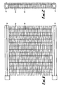
- a heat transfer apparatus comprises a plurality of heat exchange tubes 10 arranged in a spaced parallel relation and extending between an inlet manifold 12 and an outlet manifold 14.
- the tubes 10 locate through a plurality of heat exchange fins 16 in the form of plates which extend transversely of the axes of the tubes 10 in a closely spaced parallel relation.
- the heat exchanger is arranged for high pressure applications such as pressures in excess of about 35 bar, for instance in the range of 35 to 100 bar (3.5 to 10.0 MPa, or about 510 psi to 1,400 psi).
- the exchanger should be capable of working at much higher pressures, such as 280 bar or above (28.0 MPa or about 4,000 psi).
- the tubes 10 are circular in cross-section.
- each heat exchange tube may have an individual arrangement of external fins, and the heat exchange tubes can be formed into various curved shapes.
- each tube may be formed with other than fins, for example strips of aluminium helically wound onto the tube.
- the internal turbulator and the external aluminium loops, where provided, can be varied in density and spacing to provide the best compromise between the thermal performance and pressure drop for any given circumstances.
- the brazing technique has been described as providing a molecular bond without introducing other materials at boundaries, but it may be possible, for some applications, to use other techniques, including techniques which introduce other material.
- the ability to provide a continuous transition across component boundaries (and therefore uninterrupted molecular bonds therebetween), by avoiding the introduction of other materials, is considered an important advantage of the arrangement described, in view of the improved thermal conduction properties which result.
Landscapes
- Engineering & Computer Science (AREA)
- Mechanical Engineering (AREA)
- Physics & Mathematics (AREA)
- Thermal Sciences (AREA)
- General Engineering & Computer Science (AREA)
- Heat-Exchange Devices With Radiators And Conduit Assemblies (AREA)
Applications Claiming Priority (2)
| Application Number | Priority Date | Filing Date | Title |
|---|---|---|---|
| GBGB9605578.5A GB9605578D0 (en) | 1996-03-16 | 1996-03-16 | Heat transfer apparatus |
| GB9605578 | 1996-03-16 |
Publications (2)
| Publication Number | Publication Date |
|---|---|
| EP0795732A2 true EP0795732A2 (de) | 1997-09-17 |
| EP0795732A3 EP0795732A3 (de) | 1999-01-07 |
Family
ID=10790526
Family Applications (1)
| Application Number | Title | Priority Date | Filing Date |
|---|---|---|---|
| EP97301713A Withdrawn EP0795732A3 (de) | 1996-03-16 | 1997-03-13 | Wärmeaustausch-Vorrichtung |
Country Status (2)
| Country | Link |
|---|---|
| EP (1) | EP0795732A3 (de) |
| GB (1) | GB9605578D0 (de) |
Cited By (4)
| Publication number | Priority date | Publication date | Assignee | Title |
|---|---|---|---|---|
| EP1030156A3 (de) * | 1999-02-16 | 2001-09-05 | Pulverich, Peter | Wärmetauscher |
| FR2946420A1 (fr) * | 2009-06-05 | 2010-12-10 | Ls Mtron Ltd | Refroidisseur d huile pour vehicule et procede de fabrication de celui ci |
| US10512990B2 (en) | 2012-12-03 | 2019-12-24 | Holtec International, Inc. | Brazing compositions and uses thereof |
| US11504814B2 (en) | 2011-04-25 | 2022-11-22 | Holtec International | Air cooled condenser and related methods |
Family Cites Families (10)
| Publication number | Priority date | Publication date | Assignee | Title |
|---|---|---|---|---|
| JPS5844317B2 (ja) * | 1981-02-20 | 1983-10-03 | 富士重工業株式会社 | 熱交換器の製造方法 |
| JPS5963494A (ja) * | 1982-10-05 | 1984-04-11 | Showa Alum Corp | 熱交換器 |
| GB2130925A (en) * | 1982-10-19 | 1984-06-13 | S P Coil Products Limited | Heat exchanger |
| US4688311A (en) * | 1986-03-03 | 1987-08-25 | Modine Manufacturing Company | Method of making a heat exchanger |
| GB2196730B (en) * | 1986-10-21 | 1991-06-26 | Austin Rover Group | A heat exchanger |
| EP0283937A1 (de) * | 1987-03-25 | 1988-09-28 | Nihon Radiator Co., Ltd. | Flachrohr für Wärmetauscher mit eingesetzter Rippe |
| GB8910975D0 (en) * | 1989-05-12 | 1989-06-28 | Imi Radiators | Radiators |
| US5305945A (en) * | 1989-09-12 | 1994-04-26 | Modine Manufacturing Co. | Finned assembly for heat exchangers |
| JP3178051B2 (ja) * | 1991-12-11 | 2001-06-18 | 株式会社デンソー | 熱交換器及びその製造方法 |
| US5456006A (en) * | 1994-09-02 | 1995-10-10 | Ford Motor Company | Method for making a heat exchanger tube |
-
1996
- 1996-03-16 GB GBGB9605578.5A patent/GB9605578D0/en active Pending
-
1997
- 1997-03-13 EP EP97301713A patent/EP0795732A3/de not_active Withdrawn
Cited By (6)
| Publication number | Priority date | Publication date | Assignee | Title |
|---|---|---|---|---|
| EP1030156A3 (de) * | 1999-02-16 | 2001-09-05 | Pulverich, Peter | Wärmetauscher |
| FR2946420A1 (fr) * | 2009-06-05 | 2010-12-10 | Ls Mtron Ltd | Refroidisseur d huile pour vehicule et procede de fabrication de celui ci |
| US11504814B2 (en) | 2011-04-25 | 2022-11-22 | Holtec International | Air cooled condenser and related methods |
| US12240068B2 (en) | 2011-04-25 | 2025-03-04 | Holtec International | Air cooled condenser and related methods |
| US10512990B2 (en) | 2012-12-03 | 2019-12-24 | Holtec International, Inc. | Brazing compositions and uses thereof |
| US11541484B2 (en) | 2012-12-03 | 2023-01-03 | Holtec International | Brazing compositions and uses thereof |
Also Published As
| Publication number | Publication date |
|---|---|
| GB9605578D0 (en) | 1996-05-15 |
| EP0795732A3 (de) | 1999-01-07 |
Similar Documents
| Publication | Publication Date | Title |
|---|---|---|
| US11415381B2 (en) | Heat exchanger with aluminum tubes rolled into an aluminum tube support | |
| EP1714100B1 (de) | Verfahren zum Herstellen eines gelöteten Rippenrohrwärmetauschers | |
| US6412547B1 (en) | Heat exchanger and method of making the same | |
| US4744505A (en) | Method of making a heat exchanger | |
| US6173493B1 (en) | Modular heat exchanger and method of making | |
| US20130264039A1 (en) | Heat exchanger assembly and method | |
| US4858686A (en) | Heat exchanger | |
| JP2007303813A (ja) | 自己ブレーキラジエータ側板 | |
| EP1076802A1 (de) | Wärmetauscherverteilerblock mit verbesserter lötbarkeit | |
| MX2008008429A (en) | Multi-fluid heat exchanger arrangement | |
| US2443295A (en) | Method of making heat exchangers | |
| KR101562090B1 (ko) | 열교환기 관, 열교환기 관조립체 및 그 제조 방법 | |
| EP0795732A2 (de) | Wärmeaustausch-Vorrichtung | |
| AU747879B2 (en) | Modular heat exchanger and method of making | |
| HUP0200138A2 (en) | Manifold for heat exchanger | |
| US7322403B2 (en) | Heat exchanger with modified tube surface feature | |
| US5447192A (en) | Heat exchanger assembly with reinforcement and method for making same | |
| JPH10500203A (ja) | プレート型熱交換器 | |
| US20020079085A1 (en) | Turbine recuperator | |
| US5881803A (en) | Heat exchanger construction | |
| JPH0640667U (ja) | 熱交換器 | |
| JP2857896B2 (ja) | 熱交換器の製造方法 | |
| JP5540409B2 (ja) | 連結式耐圧熱交換器とその製造方法 | |
| KR101560035B1 (ko) | 열교환기 관, 열교환기 관조립체 및 그 제조 방법 | |
| WO2001023823A1 (en) | Heat exchanger |
Legal Events
| Date | Code | Title | Description |
|---|---|---|---|
| PUAI | Public reference made under article 153(3) epc to a published international application that has entered the european phase |
Free format text: ORIGINAL CODE: 0009012 |
|
| AK | Designated contracting states |
Kind code of ref document: A2 Designated state(s): DE ES FR GB IE IT NL SE |
|
| PUAL | Search report despatched |
Free format text: ORIGINAL CODE: 0009013 |
|
| AK | Designated contracting states |
Kind code of ref document: A3 Designated state(s): DE ES FR GB IE IT NL SE |
|
| RAP1 | Party data changed (applicant data changed or rights of an application transferred) |
Owner name: SPECIALIST HEAT EXCHANGERS LIMITED |
|
| STAA | Information on the status of an ep patent application or granted ep patent |
Free format text: STATUS: THE APPLICATION IS DEEMED TO BE WITHDRAWN |
|
| 18D | Application deemed to be withdrawn |
Effective date: 19990708 |