EP0795865A1 - Dispositif de support de cassette - Google Patents
Dispositif de support de cassette Download PDFInfo
- Publication number
- EP0795865A1 EP0795865A1 EP96119588A EP96119588A EP0795865A1 EP 0795865 A1 EP0795865 A1 EP 0795865A1 EP 96119588 A EP96119588 A EP 96119588A EP 96119588 A EP96119588 A EP 96119588A EP 0795865 A1 EP0795865 A1 EP 0795865A1
- Authority
- EP
- European Patent Office
- Prior art keywords
- slide
- recess
- cassette
- locking members
- pivot pin
- Prior art date
- Legal status (The legal status is an assumption and is not a legal conclusion. Google has not performed a legal analysis and makes no representation as to the accuracy of the status listed.)
- Granted
Links
- 238000004804 winding Methods 0.000 claims description 13
- 230000000903 blocking effect Effects 0.000 claims description 4
- 239000000969 carrier Substances 0.000 claims description 3
- 238000000605 extraction Methods 0.000 abstract 1
- 230000001960 triggered effect Effects 0.000 abstract 1
- 230000008719 thickening Effects 0.000 description 5
- 239000000463 material Substances 0.000 description 4
- IHQKEDIOMGYHEB-UHFFFAOYSA-M sodium dimethylarsinate Chemical class [Na+].C[As](C)([O-])=O IHQKEDIOMGYHEB-UHFFFAOYSA-M 0.000 description 3
- 238000003780 insertion Methods 0.000 description 2
- 230000037431 insertion Effects 0.000 description 2
- 238000010276 construction Methods 0.000 description 1
- 210000000056 organ Anatomy 0.000 description 1
Images

Classifications
-
- G—PHYSICS
- G11—INFORMATION STORAGE
- G11B—INFORMATION STORAGE BASED ON RELATIVE MOVEMENT BETWEEN RECORD CARRIER AND TRANSDUCER
- G11B23/00—Record carriers not specific to the method of recording or reproducing; Accessories, e.g. containers, specially adapted for co-operation with the recording or reproducing apparatus ; Intermediate mediums; Apparatus or processes specially adapted for their manufacture
- G11B23/02—Containers; Storing means both adapted to cooperate with the recording or reproducing means
- G11B23/023—Containers for magazines or cassettes
- G11B23/0233—Containers for a single cassette
Definitions
- the present invention relates to a cassette holder for the transverse storage of magnetic tape cassettes or similar sound carriers according to the preamble of the main claim.
- Such a cassette holder is described in DE 42 19 232 A1.
- This known cassette holder comprises a housing with a slide which can be inserted into the housing against a spring force and locked in the inserted position.
- the slide holds the cassette to be stored transversely, which can be easily removed or replaced in the removal position of the slide. In the removal position, the slide is clearly protruding from the housing. In the storage position, the slide can be locked and unlocked in the housing.
- cassette holders are used for storing the commercially available compact cassettes (MCC), the tape winding cores of which are freely accessible, and also digital cassettes (DCC), which have completely closed broad sides. So that with the compact cassettes, the winding cores and also the wound tape material do not get shaken perform uncontrolled movements, the well-known cassette holder has locking elements for the winding cores, which engage when the compact cassette is placed in the winding cores and secure them against rotation. Since this is not possible and also not necessary with the closed broad sides of the digital cassettes, the known cassette holder is designed in such a way that the locking element is actuated only when the compact cassettes are inserted.
- the blocking members which can be pivoted against a spring force in the blocking position, are actuated via actuating instruments when inserting a compact cassette.
- actuating elements are located in a recess into which the compact cassette engages with one of the two raised portions on its broad sides. When inserting a digital cassette which has no such elevation, the actuating elements are not actuated, so that the locking members are not pivoted out of the support plane.
- a locking member is provided for each bank winding core, which can be pivoted into the locking position against the force of an associated spring element.
- DE 43 24 265 A1 discloses a cassette holder for magnetic tape cassettes that can be inserted in the longitudinal direction, which also has locking members that engage in the tape winding cores of the magnetic tape cassettes and are aligned in the direction of insertion, and a base plate on which the magnetic tape cassettes can be locked and locked with a spring from a storage position into one Removal position extendable slide is stored.
- a sliding element that can be moved transversely to the direction of insertion by the magnetic tape cassette with lateral control wedges and pivoting elements is mounted in the base plate, with which the locking members can be pivoted into the spool hub.
- the blocking organs are on attached a transversely displaceable sliding element, whereby it is possible that the locking members are exactly aligned with the position of the associated spool hub.
- the alignment is also carried out here by the thickening of the housing on both sides of the standardized magnetic tape cassette, which depending on the alignment of the magnetic tape cassette presses on the left-hand or right-hand control wedges of the sliding element and, together with the locking devices attached to it, shifts it into the required position.
- On the longitudinally displaceable slide control edges cause the locking members to be pivoted into the locked position when the slide is inserted.
- Shafts are provided as the actuating element for the locking members, on both ends of which pivot pins protrude radially. The pivot pins thus change their lateral position in accordance with the positioning of the sliding element which can be moved laterally. If the sliding element is in a central position, the pivot pins of the locking members are ineffective.
- the cassette holders Due to the ever smaller space available in the motor vehicles, the cassette holders have to have the smallest possible height taking into account a minimal material thickness.
- the present invention is therefore based on the object of proposing a cassette holder for the transverse storage of magnetic tape cassettes or similar sound carriers, which manages with as few different components as possible and thereby manages with a lower overall height than with the known cassette holders.
- a cassette holder with the features of the main claim.
- the locking members pivotable into a locking position are each arranged in a recess in the slide and attached to a common shaft mounted on the slide.
- an actuating device arranged on the base plate is moved transversely to the direction of movement of the slide via a control edge protruding through an opening in the slide bottom surface, so that the locking members protrude from the shaft into the tape winding cores via a first pivot pin protruding from the shaft intervene when the slide has reached the storage position.
- the control edge of the actuating device is arranged in a recess in the sound carrier support surface of the slide.
- the actuating device advantageously has a control wedge which, like the pivot pin, is arranged in a common recess in the base plate and moves therein.
- the pivot pin abuts against the control wedge which is moved in the same recess in the path of the pivot pin and is rotated by it.
- the recess in the slide has a control edge which, when the slide moves from the storage position into the removal position, moves the actuating device back into the starting position and thereby unlocks the locking members.
- the shaft preferably has at least one second pivot pin protruding from the shaft, which according to an advantageous further development in the storage position in one in the Base plate arranged protrudes.
- the second pivot pin is pivoted into its original position when the slide is moved from the storage position into the removal position by an intermediate edge in the recess, which separates a deeper region of the recess from a shallower one, and thereby moves the locking members out of the tape winding cores.
- This configuration also serves the optimal use of the available height.
- a further measure for reducing the overall height is the arrangement of the control elements in a recess in which they move when the slide moves.
- the construction height is kept as low as possible by using as few individual components as possible for the movement of the locking members, taking advantage of all design options.
- the minimum wall thickness of the plastic material that is required to ensure the desired stability and durability is now decisive.
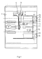
- FIG. 1 In the plan view of the base plate 1 of a cassette holder shown in FIG. 1, the individual parts shown in the following FIGS. 2 to 5, which move the slide 2 (FIG. 2 to FIG. 5) from the storage position into the removal position and lock in the storage position, not shown.
- the locking devices shown in the figures are not explained in more detail below, since they are generally known and are not the subject of the present invention.
- the recess 6 serves as free space for a pivot pin 9, which is arranged on the shaft 11 carrying the locking members 10. During the movement of the shaft 11, which is fastened to the slide 2 (not shown), the pivot pin 9 can engage with the control wedge 5, which is also arranged in the recess 6, when the latter is in line with the pivot pin 9 . As a result, the locking members 10 are moved in the desired direction.
- a second recess 12 serves to reset the locking members 10 by means of a second pivot pin 13.
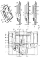
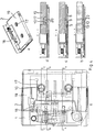
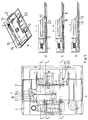
- FIGS. 2 to 5 show, in views a, the top view of the cassette holder, the parts which are not visible also being indicated by dashed lines.
- Views b, c and d show the respective cuts indicated in view a.
- View e shows the cassette holder in a perspective view.
- the cassette holder is shown with the slide 2 in the removal position.
- the locking members 10, which are fastened to the slide 2 via the shaft 11, are located in the H. inoperative position and the actuator 3 is in the unlocked position.
- the opening 14 in the slide 2 is not in the area of the control edge 4 of the actuating device 3.
- the essential part of the opening 14 is located in the lower area 15 of the support surface for the cassette.
- the standardized cassettes ensure that the digital cassette, which has no thickened housing area, rests only on the higher area 16, while the magnetic tape cassette rests both on the lower area 15 and on the higher area 16 and through the housing thickening can come into engagement with the control edge 4 of the actuating device 3 during the movement of the slide 2.
- FIG. 4 also shows the slide in the storage position, but with a magnetic tape cassette 19, the engagement of the locking members 10 in the tape winding cores 17 being evident.
- the housing thickening 18 on the magnetic tape cassette 19 is also shown.
- the shaft 11, which is rotatably mounted on the slide 2 is moved with the locking members 10 and the pivot pin 9.
- the movement of the locking members takes place in the recess 20 and the movement of the pivot pin 9 in the Recess 6 in the base plate 1. Due to the thickening of the housing 18 in the lower region 15, this presses against the control edge 4 of the actuating device 3 and moves the actuating device 3 transversely to the direction of movement of the slide 2.
- the pins 7 are located opposite the illustration in FIG. 2 End of the elongated holes 8. This also moves the control wedge 5 from its rest position in the recess 6 in the path of the pivot pin 9, so that this is forced by the further movement of the slide 2 to evade the control wedge 5 by a rotary movement. As a result, the locking members 10, as shown in the representations b, c and d of FIGS. 3 and 4, are moved upward out of the recess 20 and engage in the tape winding cores. The shaft 11 and thus the locking members 10 are locked in this position by the control wedge 5.
- the control edge 21 on the slide 2 first causes the control edge 4 on the actuating device 3 to return to the position shown in FIG. 2 .
- the control wedge 5 moves out of the effective range of the pivot pin 9 in the recess 6 and unlocks the locking members 10.
- the second pivot pin 13 which is in the lower region of the recess when the locking members 10 is erected 12 is located, against the edge 22 of the recess 12, which separates the deeper area from the shallower, moved and caused by this to rotate, which brings the locking members 10 back into their rest position, shown in Figure 2.
- the lower area of the recess 12 is an opening in the base plate, which saves material and height.
- Figure 5 shows the slider in the storage position in the event that a digital cassette is on the slider. In this case, there is no contact with it also no movement of the actuating device 3, so that the pivot pin 9 moving in the recess 6 is not caused to rotate. As a result, the locking members 10 remain in their rest position.
Landscapes
- Packaging Of Annular Or Rod-Shaped Articles, Wearing Apparel, Cassettes, Or The Like (AREA)
- Agricultural Chemicals And Associated Chemicals (AREA)
Applications Claiming Priority (2)
| Application Number | Priority Date | Filing Date | Title |
|---|---|---|---|
| DE19609998A DE19609998A1 (de) | 1996-03-14 | 1996-03-14 | Kassettenhalterung |
| DE19609998 | 1996-03-14 |
Publications (2)
| Publication Number | Publication Date |
|---|---|
| EP0795865A1 true EP0795865A1 (fr) | 1997-09-17 |
| EP0795865B1 EP0795865B1 (fr) | 2002-09-18 |
Family
ID=7788245
Family Applications (1)
| Application Number | Title | Priority Date | Filing Date |
|---|---|---|---|
| EP96119588A Expired - Lifetime EP0795865B1 (fr) | 1996-03-14 | 1996-12-06 | Dispositif de support de cassette |
Country Status (5)
| Country | Link |
|---|---|
| US (1) | US5777820A (fr) |
| EP (1) | EP0795865B1 (fr) |
| JP (1) | JP3083775B2 (fr) |
| DE (2) | DE19609998A1 (fr) |
| ES (1) | ES2182939T3 (fr) |
Families Citing this family (1)
| Publication number | Priority date | Publication date | Assignee | Title |
|---|---|---|---|---|
| US6198596B1 (en) * | 1997-08-22 | 2001-03-06 | Canon Kabushiki Kaisha | Cassette mounting device having lock lever spring disposed in cassette holder |
Citations (6)
| Publication number | Priority date | Publication date | Assignee | Title |
|---|---|---|---|---|
| DE4219232A1 (de) | 1992-06-12 | 1993-12-16 | Fischer Artur Werke Gmbh | Vorrichtung zur Aufbewahrung von Magnetbandkassetten |
| US5303993A (en) * | 1991-10-22 | 1994-04-19 | Artur Fischer Gmbh & Co. Kg. | Container for a magnetic tape cassette |
| US5363960A (en) * | 1991-06-19 | 1994-11-15 | Idn Inventions And Development Of Novelties Ag | Container for magnetic tape cassette |
| US5381897A (en) * | 1992-06-12 | 1995-01-17 | Fischerwerke, Artur Fischer Gmbh & Co. Kg | Device for storing magnetic tape cassettes |
| DE4324265A1 (de) | 1993-07-20 | 1995-01-26 | Fischer Artur Werke Gmbh | Kassettenhalterung für in Längsrichtung einschiebbare Magnetbandkassetten |
| EP0654788A1 (fr) * | 1993-11-19 | 1995-05-24 | fischerwerke Artur Fischer GmbH & Co. KG | Boîte pour cassette à bande magnétique |
Family Cites Families (3)
| Publication number | Priority date | Publication date | Assignee | Title |
|---|---|---|---|---|
| DE2462769C2 (de) * | 1974-06-05 | 1982-01-21 | IDN Inventions and Development of Novelties AG, Chur | Behälter für eine Magnetbandkassette |
| DE3904787A1 (de) * | 1989-02-17 | 1990-08-23 | Fischer Artur Werke Gmbh | Behaelter mit magnetbandkassette |
| US5402405A (en) * | 1991-03-18 | 1995-03-28 | Sony Corporation | Cassette loading apparatus |
-
1996
- 1996-03-14 DE DE19609998A patent/DE19609998A1/de not_active Withdrawn
- 1996-12-06 DE DE59609689T patent/DE59609689D1/de not_active Expired - Fee Related
- 1996-12-06 ES ES96119588T patent/ES2182939T3/es not_active Expired - Lifetime
- 1996-12-06 EP EP96119588A patent/EP0795865B1/fr not_active Expired - Lifetime
-
1997
- 1997-02-14 US US08/800,479 patent/US5777820A/en not_active Expired - Fee Related
- 1997-03-13 JP JP09058182A patent/JP3083775B2/ja not_active Expired - Fee Related
Patent Citations (6)
| Publication number | Priority date | Publication date | Assignee | Title |
|---|---|---|---|---|
| US5363960A (en) * | 1991-06-19 | 1994-11-15 | Idn Inventions And Development Of Novelties Ag | Container for magnetic tape cassette |
| US5303993A (en) * | 1991-10-22 | 1994-04-19 | Artur Fischer Gmbh & Co. Kg. | Container for a magnetic tape cassette |
| DE4219232A1 (de) | 1992-06-12 | 1993-12-16 | Fischer Artur Werke Gmbh | Vorrichtung zur Aufbewahrung von Magnetbandkassetten |
| US5381897A (en) * | 1992-06-12 | 1995-01-17 | Fischerwerke, Artur Fischer Gmbh & Co. Kg | Device for storing magnetic tape cassettes |
| DE4324265A1 (de) | 1993-07-20 | 1995-01-26 | Fischer Artur Werke Gmbh | Kassettenhalterung für in Längsrichtung einschiebbare Magnetbandkassetten |
| EP0654788A1 (fr) * | 1993-11-19 | 1995-05-24 | fischerwerke Artur Fischer GmbH & Co. KG | Boîte pour cassette à bande magnétique |
Also Published As
| Publication number | Publication date |
|---|---|
| ES2182939T3 (es) | 2003-03-16 |
| EP0795865B1 (fr) | 2002-09-18 |
| JP3083775B2 (ja) | 2000-09-04 |
| DE59609689D1 (de) | 2002-10-24 |
| US5777820A (en) | 1998-07-07 |
| DE19609998A1 (de) | 1997-09-18 |
| JPH107183A (ja) | 1998-01-13 |
Similar Documents
| Publication | Publication Date | Title |
|---|---|---|
| DE69507471T2 (de) | Antriebgerät geeignet für benutzung mit datenspeicher kassetten mit verschiedene abmessung und datenspeicherkassetten dafür | |
| DE69026984T2 (de) | System zur Aufzeichnung/Wiedergabe von Signalen auf/vom Magnetband und Gerät und Kassette zur Verwendung in diesem System | |
| EP0207111B1 (fr) | Recipient pour disques phono ou video | |
| DE3139333C2 (fr) | ||
| DE3231041C2 (de) | Aufbewahrungsbehälter für eine Kassette | |
| EP0112436A1 (fr) | Dispositif pour le rangement de supports d'enregistrement plats | |
| EP0163221A1 (fr) | Dispositif pour conserver des supports d'enregistrement, en particulier pour l'installation dans des véhicules à moteur | |
| DE3222712A1 (de) | Magnetplattenkassette, bestehend aus einem gehaeuse und einer drehbaren magnetischen platte | |
| EP0490049A2 (fr) | Récipient pour cassettes à bande magnétique | |
| DE19828619A1 (de) | Bandkassettenrollenverriegelung | |
| DE69923018T2 (de) | Aufzeichnungsträgerkassette mit federgesteuertem Verschluss | |
| DE1954735C3 (de) | Ausgleichsstück für eine Bandkassette | |
| DE2854602C2 (de) | Behälter für Magnetbandkassetten | |
| EP0134279A1 (fr) | Boîtier de stockage pour des cassettes de bande magnétique | |
| DE3137889C2 (fr) | ||
| DE60218588T2 (de) | Zugriffsystem eines Datenspeichersystems | |
| DE2935206C2 (de) | Kassette | |
| DE10220531A1 (de) | Datenspeicherbandkassette mit einer Bandspulenzentrier-Verriegelungsanordnung | |
| EP0480514A2 (fr) | Cassette pour un support d'enregistrement | |
| DE69613051T2 (de) | Aufnahme- und/oder wiedergabegerät für kassetten mindestens zweier verschiedener grössen | |
| DE69308332T2 (de) | Magnetbandkassette mit führungsblock und führungsblockstift der zweiten generation | |
| EP0795865B1 (fr) | Dispositif de support de cassette | |
| WO1981000480A1 (fr) | Cassette de bande magnetique | |
| DE4205038C2 (de) | Vorrichtung zum Verriegeln und Entriegeln eines Paares von in einer Kassette enthaltenen Bandspulen | |
| DE3610803C2 (fr) |
Legal Events
| Date | Code | Title | Description |
|---|---|---|---|
| PUAI | Public reference made under article 153(3) epc to a published international application that has entered the european phase |
Free format text: ORIGINAL CODE: 0009012 |
|
| AK | Designated contracting states |
Kind code of ref document: A1 Designated state(s): BE DE ES FR GB IT NL |
|
| 17P | Request for examination filed |
Effective date: 19980123 |
|
| GRAG | Despatch of communication of intention to grant |
Free format text: ORIGINAL CODE: EPIDOS AGRA |
|
| GRAG | Despatch of communication of intention to grant |
Free format text: ORIGINAL CODE: EPIDOS AGRA |
|
| GRAH | Despatch of communication of intention to grant a patent |
Free format text: ORIGINAL CODE: EPIDOS IGRA |
|
| 17Q | First examination report despatched |
Effective date: 20020305 |
|
| GRAH | Despatch of communication of intention to grant a patent |
Free format text: ORIGINAL CODE: EPIDOS IGRA |
|
| GRAA | (expected) grant |
Free format text: ORIGINAL CODE: 0009210 |
|
| AK | Designated contracting states |
Kind code of ref document: B1 Designated state(s): BE DE ES FR GB IT NL |
|
| REG | Reference to a national code |
Ref country code: GB Ref legal event code: FG4D Free format text: NOT ENGLISH |
|
| REF | Corresponds to: |
Ref document number: 59609689 Country of ref document: DE Date of ref document: 20021024 |
|
| ET | Fr: translation filed | ||
| PGFP | Annual fee paid to national office [announced via postgrant information from national office to epo] |
Ref country code: GB Payment date: 20021204 Year of fee payment: 7 |
|
| PGFP | Annual fee paid to national office [announced via postgrant information from national office to epo] |
Ref country code: ES Payment date: 20021216 Year of fee payment: 7 |
|
| PGFP | Annual fee paid to national office [announced via postgrant information from national office to epo] |
Ref country code: NL Payment date: 20021223 Year of fee payment: 7 |
|
| PGFP | Annual fee paid to national office [announced via postgrant information from national office to epo] |
Ref country code: FR Payment date: 20021230 Year of fee payment: 7 |
|
| PG25 | Lapsed in a contracting state [announced via postgrant information from national office to epo] |
Ref country code: BE Free format text: LAPSE BECAUSE OF NON-PAYMENT OF DUE FEES Effective date: 20021231 |
|
| GBT | Gb: translation of ep patent filed (gb section 77(6)(a)/1977) |
Effective date: 20021220 |
|
| REG | Reference to a national code |
Ref country code: ES Ref legal event code: FG2A Ref document number: 2182939 Country of ref document: ES Kind code of ref document: T3 |
|
| BERE | Be: lapsed |
Owner name: FISCHERWERKE ARTUR *FISCHER G.M.B.H. & CO. K.G. Effective date: 20021231 |
|
| PLBE | No opposition filed within time limit |
Free format text: ORIGINAL CODE: 0009261 |
|
| STAA | Information on the status of an ep patent application or granted ep patent |
Free format text: STATUS: NO OPPOSITION FILED WITHIN TIME LIMIT |
|
| PGFP | Annual fee paid to national office [announced via postgrant information from national office to epo] |
Ref country code: DE Payment date: 20030903 Year of fee payment: 8 |
|
| 26N | No opposition filed |
Effective date: 20030619 |
|
| PG25 | Lapsed in a contracting state [announced via postgrant information from national office to epo] |
Ref country code: GB Free format text: LAPSE BECAUSE OF NON-PAYMENT OF DUE FEES Effective date: 20031206 |
|
| PG25 | Lapsed in a contracting state [announced via postgrant information from national office to epo] |
Ref country code: ES Free format text: LAPSE BECAUSE OF NON-PAYMENT OF DUE FEES Effective date: 20031209 |
|
| PG25 | Lapsed in a contracting state [announced via postgrant information from national office to epo] |
Ref country code: NL Free format text: LAPSE BECAUSE OF NON-PAYMENT OF DUE FEES Effective date: 20040701 |
|
| GBPC | Gb: european patent ceased through non-payment of renewal fee |
Effective date: 20031206 |
|
| PG25 | Lapsed in a contracting state [announced via postgrant information from national office to epo] |
Ref country code: FR Free format text: LAPSE BECAUSE OF NON-PAYMENT OF DUE FEES Effective date: 20040831 |
|
| NLV4 | Nl: lapsed or anulled due to non-payment of the annual fee |
Effective date: 20040701 |
|
| REG | Reference to a national code |
Ref country code: FR Ref legal event code: ST |
|
| REG | Reference to a national code |
Ref country code: ES Ref legal event code: FD2A Effective date: 20031209 |
|
| PG25 | Lapsed in a contracting state [announced via postgrant information from national office to epo] |
Ref country code: DE Free format text: LAPSE BECAUSE OF NON-PAYMENT OF DUE FEES Effective date: 20050701 |
|
| PG25 | Lapsed in a contracting state [announced via postgrant information from national office to epo] |
Ref country code: IT Free format text: LAPSE BECAUSE OF NON-PAYMENT OF DUE FEES;WARNING: LAPSES OF ITALIAN PATENTS WITH EFFECTIVE DATE BEFORE 2007 MAY HAVE OCCURRED AT ANY TIME BEFORE 2007. THE CORRECT EFFECTIVE DATE MAY BE DIFFERENT FROM THE ONE RECORDED. Effective date: 20051206 |