EP0795949A1 - Elektrische Maschine, insbesondere Elektromotor - Google Patents
Elektrische Maschine, insbesondere Elektromotor Download PDFInfo
- Publication number
- EP0795949A1 EP0795949A1 EP97101518A EP97101518A EP0795949A1 EP 0795949 A1 EP0795949 A1 EP 0795949A1 EP 97101518 A EP97101518 A EP 97101518A EP 97101518 A EP97101518 A EP 97101518A EP 0795949 A1 EP0795949 A1 EP 0795949A1
- Authority
- EP
- European Patent Office
- Prior art keywords
- laminations
- stator
- stack
- stacks
- electric machine
- Prior art date
- Legal status (The legal status is an assumption and is not a legal conclusion. Google has not performed a legal analysis and makes no representation as to the accuracy of the status listed.)
- Withdrawn
Links
- 238000003475 lamination Methods 0.000 claims abstract description 39
- 230000005291 magnetic effect Effects 0.000 claims description 2
- 238000005520 cutting process Methods 0.000 description 2
- 230000005294 ferromagnetic effect Effects 0.000 description 2
- 238000003754 machining Methods 0.000 description 2
- 238000010420 art technique Methods 0.000 description 1
- 230000002238 attenuated effect Effects 0.000 description 1
- 238000010276 construction Methods 0.000 description 1
- 238000005553 drilling Methods 0.000 description 1
- 230000005489 elastic deformation Effects 0.000 description 1
- 230000001788 irregular Effects 0.000 description 1
- 238000010297 mechanical methods and process Methods 0.000 description 1
- 230000005226 mechanical processes and functions Effects 0.000 description 1
- 230000004048 modification Effects 0.000 description 1
- 238000012986 modification Methods 0.000 description 1
- 238000007493 shaping process Methods 0.000 description 1
- 238000004513 sizing Methods 0.000 description 1
Images


Classifications
-
- H—ELECTRICITY
- H02—GENERATION; CONVERSION OR DISTRIBUTION OF ELECTRIC POWER
- H02K—DYNAMO-ELECTRIC MACHINES
- H02K1/00—Details of the magnetic circuit
- H02K1/06—Details of the magnetic circuit characterised by the shape, form or construction
- H02K1/12—Stationary parts of the magnetic circuit
-
- H—ELECTRICITY
- H02—GENERATION; CONVERSION OR DISTRIBUTION OF ELECTRIC POWER
- H02K—DYNAMO-ELECTRIC MACHINES
- H02K5/00—Casings; Enclosures; Supports
- H02K5/24—Casings; Enclosures; Supports specially adapted for suppression or reduction of noise or vibrations
Definitions
- the present invention refers to an electric machine, such as for instance an electric motor, and it covers in particular the sizing and the shaping of the parts thereof which are subject to the magnetostrictive forces, such as rotor and stator stacks.
- the magnetic fields that are present in electrical machines generate the forces that are substantially the main function and the actual purpose of the same machines. However, they also tend to mechanically distort the working parts, ie. the parts that are involved in the operation of the machine.
- the tangential component of the electromagnetic forces act on the rotor and stator teeth and distort them in a tangential direction.
- the radial component although usually undesired, is on the other hand always present and in some cases, such as for instance in variable reluctance motors, it reaches up to quite high values and gives rise to radial distortions.
- FIG. 1 which illustrates the prior-art technique, shows a portion of a stator stack 10 for an electric variable-reluctance motor with six salient poles 11, in which the shape and the assembly of the laminations 11 can be seen to correspond to the above description.
- Motors provided with stator stacks of this type are therefore subject to the afore cited drawbacks.
- variable reluctance motors are particularly strong in their amplitude and have a shape that varies with time, with a high content of high frequencies.
- the solution according to the present invention is particularly advantageous for this type of motors, although it proves very valuable also in cutting the noise generated by all types of electric machines in general.
- the ferromagnetic parts of the motor are therefore sized in a variable manner in their axial direction. This translates into a cross-section of the motor which, correspondingly to the shape of the laminations used, is no longer constant. Since strains and natural mechanical-resonance frequencies in both radial and axial directions are a function of the shape of the laminations, by providing for this shape to vary along the stator and rotor stacks the result is obtained that vibrations in the various points of the motor will be different from each other and will neutralize each other.
- Figures 1b, 1c and 1d illustrate a schematical perspective of a portion of the stator stack of a variable reluctance motor, in which the cross-section in the axial direction of the stator yoke according to three alternative embodiments of the present invention can be seen.
- similar reference numerals are used to indicate similar or corresponding items.
- Figure 1b illustrates a stator stack 10 formed by laminations that have two different outer diameters 121, 122 grouped in an alternating manner.
- Figure 1c illustrates a stator stack 10 formed by laminations that have three different outer diameters 121, 122, 123 grouped in an alternating manner.
- Figure 1d illustrates a stator stack 10 in which both the outer diameter and the inner diameter of the yoke are variable; this can be reached by alternating groups of laminations 212, 213 having different inner and outer diameters.
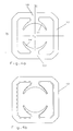
- Figures 2a and 2b illustrate a further embodiment of the invention that makes use of laminations having a single shape.
- the lamination 12 has a mechanically asymmetrical design, since the inner dimensions ra and rb and the outer dimensions Ra and Rb of the yoke are different; namely, with respect to the radial axis passing across the poles a and d , the half-yoke containing the poles b and c has smaller diameters than the half-yoke containing the poles e and f .
- the laminations When forming the stator stack, the laminations are assembled in an arrangement in which they are mutually rotated, either individually or in groups, by an angle which is equal to or a multiple of the angle between two salient poles. In this manner, a pole of the stator stack turns out to be formed by the different pole shoes (from a through to f , in Figure 2a) of the lamination 12.
- Figure 2b is a front schematical view of a stator stack formed by laminations according to Figure 2a, but rotated by an angle of 60° with respect to each other.
- Figures 3a and 3b illustrate a further application of the principle of the present invention to the pole shoes of the stator.
- Figure 3a is a front view of a portion of lamination 12 with asymmetrically shaped pole shoes.
- the pole shoes 111 and 112 are alternately provided with a lateral, mutually opposing appendix 131, 132.
- FIGs 4a and 4b illustrate an application of the invention to the stator stack of a commutator motor.
- the lamination 12 shown in Figure 4a is asymmetrical with respect to the axis a since the inner dimensions of both the yoke 14, 141 and the pole shoe 15, 151 are varying.
- a stator is obtained which has dimensions that vary along the axial direction.
- the respective dimensions can be seen to assume two different values, as this is represented with a continuous and a dashed line, respectively.
- the same lamination can be made to a shape that is aymmetrical also with respect to the axis b , so as to obtain, by rotating the various stacked laminations individually or by groups also about the axis b , four different dimensions on the four sides of the stator.
- the present invention aims at solving or, anyway, drastically improving the problem of the noise generated by electric motors and similar electric machines through an axial modification of the shape and/or the size of both rotor and stator stacks, in such a manner that the mechanical vibrations brought about by the electromagnetic forces are sharply reduced.
- an irregular configuration of the lamination stacks can also be obtained by letting the stacks undergo various possible kinds of machining or mechanical processes, for instance by drilling holes or cutting slots in the stacks.
- the desired results shall always be the outcome of a variation in the shape and/or dimensions of the stack in the axial direction thereof.
Landscapes
- Engineering & Computer Science (AREA)
- Power Engineering (AREA)
- Iron Core Of Rotating Electric Machines (AREA)
- Motor Or Generator Cooling System (AREA)
- Control Of Ac Motors In General (AREA)
Applications Claiming Priority (2)
| Application Number | Priority Date | Filing Date | Title |
|---|---|---|---|
| ITPN960017 | 1996-03-12 | ||
| IT96PN000017A ITPN960017A1 (it) | 1996-03-12 | 1996-03-12 | Macchina elettrica, in particolare motore elettrico |
Publications (1)
| Publication Number | Publication Date |
|---|---|
| EP0795949A1 true EP0795949A1 (de) | 1997-09-17 |
Family
ID=11395117
Family Applications (1)
| Application Number | Title | Priority Date | Filing Date |
|---|---|---|---|
| EP97101518A Withdrawn EP0795949A1 (de) | 1996-03-12 | 1997-01-31 | Elektrische Maschine, insbesondere Elektromotor |
Country Status (3)
| Country | Link |
|---|---|
| US (1) | US5861699A (de) |
| EP (1) | EP0795949A1 (de) |
| IT (1) | ITPN960017A1 (de) |
Cited By (3)
| Publication number | Priority date | Publication date | Assignee | Title |
|---|---|---|---|---|
| EP0884824A1 (de) * | 1997-06-15 | 1998-12-16 | Rainer Born | Statorpakket aus unterschiedlichen Blechen für elektrische Maschinen mit Grammespulen |
| US6072260A (en) * | 1998-01-20 | 2000-06-06 | Switched Reluctance Drives Limited | Noise reduction in reluctance machines |
| US6093993A (en) * | 1998-05-14 | 2000-07-25 | Switched Relutance Drives Limited | Set of laminations for a switched reluctance machine |
Families Citing this family (27)
| Publication number | Priority date | Publication date | Assignee | Title |
|---|---|---|---|---|
| CA2278726C (en) * | 1997-01-27 | 2004-08-31 | Immersion Corporation | Method and apparatus for providing high bandwidth, realistic force feedback including an improved actuator |
| JPH10304608A (ja) * | 1997-04-21 | 1998-11-13 | Hitachi Ltd | 電動機 |
| USD443585S1 (en) | 1999-01-25 | 2001-06-12 | Toshiba Carrier Corporation | Core for a stator |
| JP3383251B2 (ja) * | 1999-12-27 | 2003-03-04 | 三菱電機株式会社 | 車両用交流発電機の固定子 |
| JP3078288B1 (ja) * | 2000-01-25 | 2000-08-21 | 三菱電機株式会社 | 車両用交流発電機 |
| EP2385518A3 (de) * | 2000-05-24 | 2012-02-15 | Immersion Medical, Inc. | Haptische Vorrichtungen mit elektroaktiven Polymeren |
| US6424070B1 (en) | 2000-08-14 | 2002-07-23 | Moog Inc. | Magnetically centering torque motor |
| US7182691B1 (en) * | 2000-09-28 | 2007-02-27 | Immersion Corporation | Directional inertial tactile feedback using rotating masses |
| US7084854B1 (en) | 2000-09-28 | 2006-08-01 | Immersion Corporation | Actuator for providing tactile sensations and device for directional tactile sensations |
| US7623114B2 (en) | 2001-10-09 | 2009-11-24 | Immersion Corporation | Haptic feedback sensations based on audio output from computer devices |
| WO2004093298A1 (ja) * | 2003-04-11 | 2004-10-28 | Mitsubishi Denki Kabushiki Kaisha | 永久磁石式電動機 |
| ITTO20030421A1 (it) * | 2003-06-05 | 2004-12-06 | Varian Spa | Pompa da vuoto compatta |
| US8232969B2 (en) * | 2004-10-08 | 2012-07-31 | Immersion Corporation | Haptic feedback for button and scrolling action simulation in touch input devices |
| US7825903B2 (en) * | 2005-05-12 | 2010-11-02 | Immersion Corporation | Method and apparatus for providing haptic effects to a touch panel |
| US7709991B2 (en) * | 2005-12-08 | 2010-05-04 | A. O. Smith Corporation | Rotor assembly for an electric machine including a vibration damping member and method of manufacturing same |
| US8542105B2 (en) * | 2009-11-24 | 2013-09-24 | Immersion Corporation | Handheld computer interface with haptic feedback |
| JP5572508B2 (ja) * | 2010-09-30 | 2014-08-13 | 日立オートモティブシステムズ株式会社 | 回転電機 |
| USD647478S1 (en) * | 2010-10-20 | 2011-10-25 | Johnson Electric S.A. | Rotor core for an electric motor |
| FR2979495A1 (fr) * | 2011-08-30 | 2013-03-01 | Leroy Somer Moteurs | Carcasse rotorique. |
| US9634529B2 (en) * | 2011-12-05 | 2017-04-25 | Fisher & Paykel Appliances Ltd. | Electrical machine |
| US8479378B1 (en) * | 2012-02-09 | 2013-07-09 | John Pairaktaridis | Methods of manufacturing a stator core for a brushless motor |
| USD718239S1 (en) * | 2012-12-03 | 2014-11-25 | Danfoss (Tianjin) Ltd. | Motor spacer |
| US20160315509A1 (en) * | 2015-04-27 | 2016-10-27 | Ford Global Technologies, Llc | Electric Machine for a Vehicle |
| CN106533000A (zh) * | 2015-09-10 | 2017-03-22 | 德昌电机(深圳)有限公司 | 单相永磁电机 |
| USD824853S1 (en) * | 2017-07-26 | 2018-08-07 | Johnson Electric S.A. | Rotor core |
| WO2020177411A1 (zh) * | 2019-03-01 | 2020-09-10 | 艾默生环境优化技术(苏州)有限公司 | 定子以及包括其的电机和压缩机 |
| USD1041418S1 (en) * | 2022-12-16 | 2024-09-10 | Virien, Inc. | Rotor lamination for a generator |
Citations (4)
| Publication number | Priority date | Publication date | Assignee | Title |
|---|---|---|---|---|
| US3606674A (en) * | 1969-03-28 | 1971-09-21 | Gen Motors Corp | Method of manufacturing magnetic cores for dynamoelectric machines and laminations therefor |
| JPS57180339A (en) * | 1981-04-29 | 1982-11-06 | Mitsubishi Electric Corp | Field core for rotary electric machine |
| GB2194104A (en) * | 1986-08-15 | 1988-02-24 | Marathon Electric Mfg | Laminated stator core unit for dynamo-electric machine |
| US5300845A (en) * | 1993-04-05 | 1994-04-05 | General Electric Company | Banded electromagnetic stator core |
Family Cites Families (11)
| Publication number | Priority date | Publication date | Assignee | Title |
|---|---|---|---|---|
| US3959678A (en) * | 1972-10-02 | 1976-05-25 | General Electric Company | Concentrated winding salient-pole shaded pole motors having multiple short circuited shading coils for each pole |
| FR2497419B1 (fr) * | 1980-12-30 | 1986-04-18 | Papst Motoren Gmbh & Co Kg | Moteur a courant continu sans collecteur a double impulsion |
| US5123155A (en) * | 1983-03-25 | 1992-06-23 | L. H. Carbide Corporation | Apparatus and method for manufacturing laminated parts |
| EP0180815B2 (de) * | 1984-10-19 | 1994-12-28 | Kollmorgen Corporation | Variable Reluktanzmaschine mit variabler Geschwindigkeit |
| US4678960A (en) * | 1985-08-01 | 1987-07-07 | General Electric Company | Metallic halide electric discharge lamps |
| DE3700774C2 (de) * | 1986-01-13 | 1998-11-12 | Papst Motoren Gmbh & Co Kg | Kollektorlose Gleichstrommaschine |
| US5331245A (en) * | 1986-01-13 | 1994-07-19 | Papst Licensing Gmbh | Permanent magnet excited electric motor with improved torque ripple |
| DE3608472C2 (de) * | 1986-03-14 | 1994-04-07 | Bosch Gmbh Robert | Verfahren zur Geräuschminderung bei einer elektrischen Maschine und nach diesem Verfahren hergestellte elektrische Maschine, insbesondere Drehstromgenerator für Fahrzeuge |
| US4854034A (en) * | 1988-05-27 | 1989-08-08 | General Electric Company | Method for producing a stack of laminations with skewed conductor slots |
| US5122697A (en) * | 1990-04-30 | 1992-06-16 | Emerson Electric Co. | Hybrid single-phase variable reluctance motor |
| US5604388A (en) * | 1994-02-16 | 1997-02-18 | Emerson Electric Co. | Switched reluctance rotor molded lug |
-
1996
- 1996-03-12 IT IT96PN000017A patent/ITPN960017A1/it not_active Application Discontinuation
-
1997
- 1997-01-31 EP EP97101518A patent/EP0795949A1/de not_active Withdrawn
- 1997-02-25 US US08/805,288 patent/US5861699A/en not_active Expired - Fee Related
Patent Citations (4)
| Publication number | Priority date | Publication date | Assignee | Title |
|---|---|---|---|---|
| US3606674A (en) * | 1969-03-28 | 1971-09-21 | Gen Motors Corp | Method of manufacturing magnetic cores for dynamoelectric machines and laminations therefor |
| JPS57180339A (en) * | 1981-04-29 | 1982-11-06 | Mitsubishi Electric Corp | Field core for rotary electric machine |
| GB2194104A (en) * | 1986-08-15 | 1988-02-24 | Marathon Electric Mfg | Laminated stator core unit for dynamo-electric machine |
| US5300845A (en) * | 1993-04-05 | 1994-04-05 | General Electric Company | Banded electromagnetic stator core |
Non-Patent Citations (1)
| Title |
|---|
| PATENT ABSTRACTS OF JAPAN vol. 007, no. 027 (E - 156) 3 February 1983 (1983-02-03) * |
Cited By (3)
| Publication number | Priority date | Publication date | Assignee | Title |
|---|---|---|---|---|
| EP0884824A1 (de) * | 1997-06-15 | 1998-12-16 | Rainer Born | Statorpakket aus unterschiedlichen Blechen für elektrische Maschinen mit Grammespulen |
| US6072260A (en) * | 1998-01-20 | 2000-06-06 | Switched Reluctance Drives Limited | Noise reduction in reluctance machines |
| US6093993A (en) * | 1998-05-14 | 2000-07-25 | Switched Relutance Drives Limited | Set of laminations for a switched reluctance machine |
Also Published As
| Publication number | Publication date |
|---|---|
| ITPN960017A1 (it) | 1997-09-12 |
| US5861699A (en) | 1999-01-19 |
| ITPN960017A0 (de) | 1996-03-12 |
Similar Documents
| Publication | Publication Date | Title |
|---|---|---|
| EP0795949A1 (de) | Elektrische Maschine, insbesondere Elektromotor | |
| US7939982B2 (en) | Motor with lobed rotor having uniform and non-uniform air gaps | |
| US5260620A (en) | Asynchronous induction motor | |
| US5091668A (en) | Motor having flux-concentrating permanent magnets | |
| EP0426376B1 (de) | Rotor für einen getakteten Reluktanzmotor | |
| US3221195A (en) | Core for dynamoelectric machines | |
| US4472651A (en) | Permanent magnet rotor | |
| US10720801B2 (en) | Electric machine with a stator having slots at the tooth for reducing the fundamental wave of the magnetic flux | |
| US20090001831A1 (en) | Axial Field Electric Motor and Method | |
| US10574099B2 (en) | Optimized stator tooth for electric motor/generator | |
| US4053801A (en) | Armature structure for permanent magnet d-c motor | |
| US4525925A (en) | Method of making permanent magnet rotor | |
| EP1890372A2 (de) | Motoranker mit verteilter Wicklung zur Lichtbogenreduzierung | |
| EP1628380A1 (de) | Statornutöffnungen für einen permanentmagnetischen Motor | |
| CN112003392B (zh) | 永磁电机及具有其的洗衣机 | |
| JP2021526783A (ja) | 回転電気機械の為の固定子 | |
| JP6507956B2 (ja) | 永久磁石式回転電機 | |
| JP2011019398A (ja) | 固定子及び密閉型圧縮機及び回転機 | |
| GB2491880A (en) | Non-uniformly spaced claw-pole stator | |
| EP0955714A2 (de) | Dauermagnetische Synchronmaschine | |
| US5760519A (en) | Stator for electric machine and lamination thereof | |
| WO2017031178A1 (en) | Low profile axial flux permanent magnet synchronous motor | |
| JP3233945B2 (ja) | 爪形磁極機械 | |
| KR102243151B1 (ko) | 감소된 와전류 손실들 및 높은 자기 전도도와 기계적 강도를 갖는 전기 기계용 고정자 코어 또는 회전자 코어 | |
| JPWO2021079508A1 (ja) | 電動機 |
Legal Events
| Date | Code | Title | Description |
|---|---|---|---|
| PUAI | Public reference made under article 153(3) epc to a published international application that has entered the european phase |
Free format text: ORIGINAL CODE: 0009012 |
|
| AK | Designated contracting states |
Kind code of ref document: A1 Designated state(s): AT CH DE DK ES FR GB IT LI SE |
|
| 17P | Request for examination filed |
Effective date: 19971013 |
|
| 17Q | First examination report despatched |
Effective date: 19990624 |
|
| STAA | Information on the status of an ep patent application or granted ep patent |
Free format text: STATUS: THE APPLICATION IS DEEMED TO BE WITHDRAWN |
|
| 18D | Application deemed to be withdrawn |
Effective date: 19991105 |