EP0796017A2 - Bilddatenverarbeitungsverfahren und -vorrichtung - Google Patents
Bilddatenverarbeitungsverfahren und -vorrichtung Download PDFInfo
- Publication number
- EP0796017A2 EP0796017A2 EP97103741A EP97103741A EP0796017A2 EP 0796017 A2 EP0796017 A2 EP 0796017A2 EP 97103741 A EP97103741 A EP 97103741A EP 97103741 A EP97103741 A EP 97103741A EP 0796017 A2 EP0796017 A2 EP 0796017A2
- Authority
- EP
- European Patent Office
- Prior art keywords
- data
- field
- image
- block
- motion
- Prior art date
- Legal status (The legal status is an assumption and is not a legal conclusion. Google has not performed a legal analysis and makes no representation as to the accuracy of the status listed.)
- Withdrawn
Links
Images


Classifications
-
- H—ELECTRICITY
- H04—ELECTRIC COMMUNICATION TECHNIQUE
- H04N—PICTORIAL COMMUNICATION, e.g. TELEVISION
- H04N7/00—Television systems
- H04N7/01—Conversion of standards, e.g. involving analogue television standards or digital television standards processed at pixel level
-
- H—ELECTRICITY
- H04—ELECTRIC COMMUNICATION TECHNIQUE
- H04N—PICTORIAL COMMUNICATION, e.g. TELEVISION
- H04N19/00—Methods or arrangements for coding, decoding, compressing or decompressing digital video signals
- H04N19/10—Methods or arrangements for coding, decoding, compressing or decompressing digital video signals using adaptive coding
- H04N19/102—Methods or arrangements for coding, decoding, compressing or decompressing digital video signals using adaptive coding characterised by the element, parameter or selection affected or controlled by the adaptive coding
- H04N19/103—Selection of coding mode or of prediction mode
- H04N19/112—Selection of coding mode or of prediction mode according to a given display mode, e.g. for interlaced or progressive display mode
-
- H—ELECTRICITY
- H04—ELECTRIC COMMUNICATION TECHNIQUE
- H04N—PICTORIAL COMMUNICATION, e.g. TELEVISION
- H04N5/00—Details of television systems
- H04N5/76—Television signal recording
- H04N5/91—Television signal processing therefor
- H04N5/92—Transformation of the television signal for recording, e.g. modulation, frequency changing; Inverse transformation for playback
- H04N5/926—Transformation of the television signal for recording, e.g. modulation, frequency changing; Inverse transformation for playback by pulse code modulation
- H04N5/9261—Transformation of the television signal for recording, e.g. modulation, frequency changing; Inverse transformation for playback by pulse code modulation involving data reduction
- H04N5/9264—Transformation of the television signal for recording, e.g. modulation, frequency changing; Inverse transformation for playback by pulse code modulation involving data reduction using transform coding
-
- H—ELECTRICITY
- H04—ELECTRIC COMMUNICATION TECHNIQUE
- H04N—PICTORIAL COMMUNICATION, e.g. TELEVISION
- H04N5/00—Details of television systems
- H04N5/76—Television signal recording
- H04N5/78—Television signal recording using magnetic recording
- H04N5/781—Television signal recording using magnetic recording on disks or drums
-
- H—ELECTRICITY
- H04—ELECTRIC COMMUNICATION TECHNIQUE
- H04N—PICTORIAL COMMUNICATION, e.g. TELEVISION
- H04N5/00—Details of television systems
- H04N5/76—Television signal recording
- H04N5/78—Television signal recording using magnetic recording
- H04N5/782—Television signal recording using magnetic recording on tape
- H04N5/783—Adaptations for reproducing at a rate different from the recording rate
Definitions
- the present invention relates to a digital image data storage apparatus, a digital image data transfer apparatus and a digital image data broadcast apparatus including image an data encoder and decoder.
- FIG. 20A is a block diagram of a process of image data compression
- Fig.20B is a block diagram of a process of image data decompression.
- original image data should be generated line by line from each field, the composite image data is divided into N*N pixel blocks, then those blocks are encoded by the method of the Discrete Cosine Transformation (DCT), which is a two-dimensional orthogonal transformation.
- DCT Discrete Cosine Transformation
- signal energy of the image data is biased at low frequency, and it is expected that high frequency components are transformed to "0" by applying the DCT and proper quantization. Therefore, highly efficient image data compression can be achieved by nullifying those components.
- the first field and second field of the composite image data are less related. Therefore, non-"0" components can appear more in the high frequency range even after applying the DCT and proper quantization.
- the total amount of available bits allotted as bits for coding the compressed data is fixed in the encoding process, and compressing efficiency may be decreased by allotting the available bits to those non-"0" components in the high frequency range.
- digital video recorders usually have a function for selecting the frame DCT or the field DCT in advance by detecting that the block data is "static block data" with less motion or "motion block data” with more motion.
- the invention provides an image data processing apparatus having high quality image display capability without deformation and having high compression efficiency when displaying interlace-scanned motion block data or motion frame data as a static image.
- a first aspect of the image data processing apparatus of the present invention is characterized by means for reproducing and supplementing field data of one side from field data of the other side and completing frame data by compositing a base field data and a reproduced field data during data processing for displaying data as static image.
- a second aspect of the image data processing apparatus of the present invention is characterized by means for controlling the applied field data supplementation for input image data according to added inter-field motion information and means for compositing frame data as the static image.
- the inter-field motion information is determined by means of an inter-field differential value of each block, which, if it is larger than a set value, this block data is detected as a motion block data, whereas if it is smaller than a set value, this block data is detected as a static block data.
- a third aspect of the image data processing apparatus of the present invention is characterized by means for interlacing input image data, compressing the interlaced image data, decompressing the compressed image data, supplementing interlaced field data of the decompressed image data and composing frame data of a static image.
- the compression is a means by which the input data are divided into blocks and transformed by the DCT.
- the supplementation is a means by which interlaced field data are calculated from field data from the other side .
- a fourth aspect of the image data processing apparatus of the present invention is characterized by means for compressing original input image data by transformation.
- the transformation is a way to detect motion block data from input block data, calculating added value and differential value of contiguous fields, and applying the orthogonal transformation to the differential value in order to make components in the high frequency range be "0".
- a fifth aspect of the image data processing apparatus of the present invention is characterized by means for decompressing compressed image data according to the inter-field motion information.
- the compression can use either the spatial orthogonal transformation or a spatial-temporal orthogonal transformation on input image data depending on the accompanying inter-field motion information.
- the decompression regards the temporal components at high frequency range as "0" and applies the inverse spatial-temporal orthogonal transformation.
- a sixth aspect of the image data processing apparatus of the present invention is characterized by means for controlling decompression by the accompanying motion information and the playback type information specifying that data displayed should be motion picture or static image.
- the inter-field motion information is information which describes block data as a motion block or a static block.
- the decompression is a means for applying the usual inverse spatial-temporal orthogonal transformation to motion block data in the case that the playback type information is "motion picture", and for applying the inverse spatial orthogonal transformation to one field of motion block data in order to compose frame data in the case that the playback type information is "static image".
- deformation of the image can be reduced by using one side of field data and supplementing with the other side of field data. Because one side of field data is used, many bits can be allotted for encoding each block in compression and better quality of image display is possible.
- temporal components in motion block data are regarded as "0", and image deformation related to motion can be reduced. Furthermore, temporal components in motion block data are regarded as being "0" in compression, and many bits can be allotted to higher use for the decompression process, resulting in a better quality image display.
- Fig. 1 is a block diagram representation of a system of a first embodiment of the present invention.
- Fig. 2 shows one example process of a frame supplementor 103 of the first embodiment of the present invention.
- Fig. 3 is a block diagram representation of a system of a second embodiment of the present invention.
- Fig. 4 shows one example process of a motion information detector 302 of the second embodiment of the present invention.
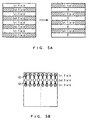
- Fig. 5 shows one example process of a block supplementor 305 of the second embodiment of the present invention.
- Fig. 6 is a block diagram representation of a system of a third embodiment of the present invention.
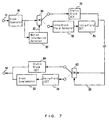
- Fig. 7 is a block diagram representation of a system of a fourth embodiment of the present invention.
- Fig. 8 shows one example process of a field selector 702 of the fourth embodiment of the present invention.
- Fig. 9 is a block diagram representation of a system of a fifth embodiment of the present invention.
- Fig. 10 shows a pixel layout in a block of a motion block DCT 901 of the fifth embodiment of the present invention.
- Fig. 11 shows one example process of a nullifier 902 of the fifth embodiment of the present invention.
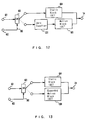
- Fig. 12 is a block diagram representation of a system of a sixth embodiment of the present invention.
- Fig. 13 is a block diagram representation of a system of a seventh embodiment of the present invention.
- Fig. 14 shows one example process of an expanded motion block Inverse DCT (IDCT) 1301 of the seventh embodiment of the present invention.
- IDCT Inverse DCT
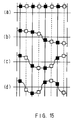
- Fig. 15 shows one example process of sample points selection of the expanded motion block IDCT 1301.
- Fig. 16 is a block diagram representation of a system of a eighth embodiment of the present invention.
- Fig. 17 shows one example process of an adaptive motion block IDCT 1601 of the eighth embodiment of the present invention.
- Fig. 18 is a block diagram representation of one configuration of the adaptive motion block IDCT 1601.
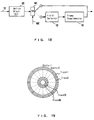
- Fig. 19 shows a physical format of a flexible disk.
- Fig. 20A is a block diagram representation of an image data compression process of a conventional system.
- Fig. 20B is a block diagram representation of an image data decompression process of a conventional system.
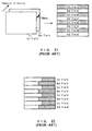
- Fig. 21 shows a block composition of interlace-scanned image data.
- Fig. 22 shows a composited static image of objects with rapid motion.
- the Discrete Cosine Transformation is used for the orthogonal transformation and the Inverse Discrete Cosine Transformation (IDCT) is used for the inverse orthogonal transformation.
- the two-dimensional DCT means the plane DCT without a temporal factor
- the three-dimensional DCT means the plane-temporal DCT.
- FIG. 1 there are an image data input node 101, a field selector 102, a frame supplementor 103 and an image data output node 104.
- Image data having two fields of data is inputted from the image data input node 101 and transmitted to the field selector 102, and one of the two fields of that data is selected.
- the first field is selected in this case.
- the selected first field data is supplied to the frame supplementor 103, and the interlaced data (the second field data in this case) is calculated and supplemented based on the first field data by the frame supplementor 103.
- the two fields of data are then composited and outputted from the image data output node 104 as a static image.
- Fig.2 shows one example process of the frame supplementor 103 in more detail.
- (a) shows pixel data of supplied field data
- (b) and (c) show doubled pixel data in lines from (a), and (c) will be output data.
- pixel data of the "2n” line of (b) In order to obtain pixel data of the "2n” line of (b), pixel data of the "n” line and “n+1” line of (a) are composited by the ratio of 3/4 : 1/4. In the same manner, in order to obtain pixel data of the "2n+1” line of (b), pixel data of the "n” line and "n+1” line of (a) are composited by the ratio of 1/4 : 3/4.
- pixel data of the "2n” lines of (c) are composited by the ratio of -1/2 : 2 : -1/2.
- a feature of the series of the above pixel data transformation is that there is almost no loss in gain in a vertical direction of frequency in the range below the Nyquist rate. Therefore, when displaying the image processed by the above transformation process, the vertical resolution of the processed image is almost the same as that of the original image.
- the gap lying between two fields of data will be reduced by eliminating the temporal-based components from the playback static image, and image deformation at its edge can be reduced.
- the vertical resolution will not be reduced by this supplementation.
- This first embodiment of the present invention is especially advantageous for capturing and displaying data of motion objects as a static image.
- a block separator 301 there are a block separator 301, a motion detector 302, a motion information 303, a switch 304 and a block supplementor 305.
- the rest of the modules in Fig.3 are the same modules referenced above with the same numerals.
- Image data inputted from the image data input node 101 is arranged into a frame line by line serially from each field and separated by an 8 * 8 pixel block by the block seperator 301.
- Block data is supplied to the switch 304 via the motion detector 302.
- the motion detector 302 adds a motion information, which is a flag bit data indicating block data type. If supplied block data is detected as a static block, the bit will be "0", whereas if it is detected as a motion block, the flag bit will be "1".
- FIG.4 One example method of the above block data type detecting by the motion detector 302 is shown in Fig.4.
- the value of each pixel in a block is represented as X(m,n). If the figure calculated by the following equation upon substitution of each pixel value is larger than a set value, the block data type is analyzed as a "motion block", if not, it is analyzed as a "static block".
- the block data supplied to the switch 304 is switched to the image data output node 104 directly. If the motion information is "0", the block data is switched to the block supplementor 305.
- the block supplementor 305 shown in Fig.5A the first field is selected from the frame composed of first and second fields, and the second field is interlaced. Then the second field is reproduced and supplemented based on the first field as shown in Fig.5B.
- field supplementation is taking the mean value of contingent pixels in the vertical direction.
- the motion block data supplemented by the block supplementor 305 is supplied to the image data output node 104 and displayed as a static image.
- a block compressed image data input node 601 there are a block compressed image data input node 601, a motion information input node 602, a switch 603, a static block IDCT 604 and a motion block IDCT 605.
- the rest of the modules are the same as the modules referenced above with the same numerals.
- Compressed image data from the compressed image data input node 601 and motion information 303 from the motion information input node 602 are supplied to the switch 603. If the motion information 303 is "0", the compressed image data is switched to the static block IDCT 604 and processed with the two dimensional frame DCT. If the motion information 303 is "1", the compressed image data is switched to the motion block IDCT 605 and processed with the three dimensional plane-temporal DCT. The processed motion block data is supplied to the block supplementor 305 and supplementation of the interlaced field occurs by the same method as in the second embodiment.
- the output data from the static block IDCT 604 or the block supplementor 305 is output as static image via the image data output node 104.
- the present invention can be applied by using the static block IDCT and the motion block IDCT.
- This third embodiment of the present invention is also advantageous for capturing and displaying data of motion objects as a static image.
- a static block DCT 701 a field selector 702, an intra-field DCT 703 and an intra-field IDCT 704.
- the rest of the modules are the same as the modules referenced above with the same numerals.
- Inputted image data is separated into blocks by the block seperator 301,
- the block data is switched to the static block DCT 701 and transformed by the two-dimensional frame DCT.
- the block data is switched to the field seperator 702.
- Fig.8A shows a block data configuration supplied to the field selector 702.
- the field seperator 702 selects the first field only, nullifies the second field, processes the input data as shown in Fig.8B, and supplies the processed data to the intra-field DCT 703.
- the intra-field DCT 703 is the two dimensional DCT and processes 4 * 8 matrix DCT to the hatched area of Fig.8B.
- the DCT coefficients calculated by the static block DCT 701 and the intra-field DCT 703 are quantized and encoded and accompanied by motion information 303. Encoded data can be storaged onto media or transferred via network.
- the intra-field IDCT 704 is the two-dimensional IDCT and processes a 4 * 8 matrix IDCT only to the upper 4 lines of input block data as shown in Fig.8B, and interlaced field data is supplemented by the same method as shown in Fig.5B.
- This fourth embodiment of the present invention is especially advantageous for an apparatus such as a digital still camera for capturing, storing or transferring data of motion objects as a static image.
- a motion block DCT 901 there are a motion block DCT 901, a nullifier 902 and a compressed image data output node 903 and the rest of the modules are the same as the modules referenced above with the same numerals.
- Inputted image data is separated into blocks by the block seperator 301, the separated block data is switched to the static block DCT 701 or to the motion block DCT 901 by the switch 304 depending on the accompanying motion information.
- the block data is switched to the static block DCT 701
- the block data is switched to the motion block DCT 901.
- the static block data is transformed with the two-dimensional frame DCT by the static block DCT 701 and supplied to the compressed image data output node 903.
- the integral value (first field pixel + second field pixel) and the differential value (first field pixel - second field pixel) of each set of corresponding pixels between first field and second field are calculated, and the integral value and the differential value are transformed by the two dimensional 4 * 8 matrix DCT independently.
- the nullifier 902 nullifies high frequency vertical components of the DCT coefficients of the differential value supplied from the motion block DCT 901 as shown in Fig.11, and then supplies processed data to the compressed image data output node 903.
- the differential value between the two fields represents the amount of temporal change of each pixel.
- the motion components can be eliminated by nullifying the differential value, and the deformation seen in the edge of an image can be reduced when the image is displayed as a static image.
- more bits can be allotted to the integral value of the two fields, which is important from the viewpoint of a person's sense of sight, by reducing the bits allocated to the differential value of the two fields. Therefore, display quality will be improved.
- decoded data can be displayed as a static image with less deformation.
- nullifier 1201 there is a nullifier 1201 and the rest of modules are the same as the modules referenced above with the same numerals.
- Compressed image data from the compressed image data input node 601 and motion information 303 from the motion information input node 602 are supplied to the switch 603.
- the supplied data are switched to the static block IDCT 604 or to the nullifier 1201 by the switch 603 depending on accompanying motion information.
- static block data data is transformed with the two-dimensional frame IDCT by the static block IDCT 604.
- motion block data the data is supplied to the nullifier 1201.
- the nullifier 1201 nullifies coefficients of high frequency vertical components (of the differential value of two fields). For example, all coefficients of high frequency vertical components are nullified by the nullifier 1201, then block data is transformed with the three-dimensional plane-temporal IDCT by the motion block IDCT 605.
- the output image data from the static block IDCT 604 and the motion block IDCT 605 are supplied to the image data output node 104 and displayed as a static image.
- the temporal-based components of the motion block are eliminated at the decoding process, and the data can be displayed as a static image with less deformation.
- Compressed image data from the compressed image data input node 601 and motion information 303 from the motion information input node 602 are supplied to the switch 603.
- the supplied data are switched to the static block IDCT 604 or to the expanded motion IDCT 1301 by the switch 603, depending on the accompanying motion information.
- the output image data from the static block IDCT 604 and the expanded motion block IDCT 1301 are supplied to the image data output node 104 and displayed as a static image.
- a and B are matrices of pixel data.
- the data of A is from the first field, and the data of B is from the second field.
- DCT(X) means that matrix X is transformed by the DCT.
- DCT(A+B) and DCT(A-B) are supplied to the expanded motion block IDCT 1301.
- the IDCT is a way to obtain pixel data by superposing fundamental waveform signals with weighting at each sample point.
- DCT(A) has the eighth order in the rows of the matrix. Therefore, 8 pixel data can be obtained by superposing 8 fundamental waveform signals at 8 sample points.
- DCT(A) has the fourth order in the columns of the matrix. Therefore, there are 4 fundamental waveform signals at 4 sample points.
- the temporal-based components of the motion block are eliminated in the decoding process by using one side field data only, and the data can be displayed as a static image with less deformation.
- the supplied compressed data are the DCT(A+B) and the DCT (A-B), and it is preferable that the supplied compressed data be the DCT(A) or the DCT(B).
- either DCT(A) or DCT(B) is supplied to the expanded motion block IDCT 1301 directly and can be applied to the IDCT by the same process shown in this embodiment.
- the playback type information 1602 is information which specifies that the output image should be as a static image or as a motion picture.
- Compressed image data from the compressed image data input node 601 and motion information 303 from the motion information input node 602 are supplied to the switch 603.
- the supplied data are switched to the static block IDCT 604 or to the adaptive motion IDCT 1601 by the switch 603, depending on accompanying motion information. If data are static block data, data are switched to the static block IDCT 604 and processed with the inverse two-dimensional plane DCT. If data are motion block data, data are switched to the adaptive motion block IDCT 1601.
- the playback type information 1602 is also supplied to the adaptive motion block IDCT 1601.
- the playback type information 1602 is a kind of flag bit, for example, a "0" which specifies that the data is to be played back as motion pictures, or a "1" which specifies that the data is to be played back as a static image.
- the supplied motion block data is processed with the proper IDCT depending on the playback type information 1602 in the adaptive motion block IDCT 1601.
- the obtained data from the static block IDCT 604 or the adaptive motion block IDCT 1601 are displayed via the image data output node 104.
- Fig.17 shows a detailed configuration of the adaptive motion block IDCT 1601. Referring to Fig.17, there are an input data 1701 compressed with the DCT, and a switch 1702. The rest of the modules are the same as the modules referenced above with the same numerals.
- the DCT compressed motion block data 1701 is supplied to the switch 1702.
- the playback information 1602 is "0”
- data is switched to the motion block IDCT 605
- the conventional three-dimension spatial-temporal IDCT is applied to the supplied data and data are processed as motion pictures.
- the function of the expanded motion block IDCT 1301 is the same as the function explained above for the seventh embodiment. Therefore, data also can be displayed as a static image with less deformation.
- data can be displayed as either motion pictures or a static image with less deformation by selecting the DCT to be applied to motion block data depending on the playback type information.
- FIG.16 shows a modified configuration of the adaptive motion block IDCT 1601 which was described above in the eighth embodiment.
- Fig.18 shows the modified configuration of the adaptive motion block IDCT 1601 of this embodiment.
- a switch 1801. The rest of the modules are the same as the modules referenced above with the same numerals.
- the DCT compressed motion block data 1701 is processed with the IDCT by the motion block IDCT 605, and then supplied to the switch 1801.
- the switch 1801 switches data to the output node 104 directly.
- the switch 1801 switches data to the field selector 102.
- the first field data is selected by the field selector 102, interlaced data are supplemented by the frame supplementor 103, and processed data are output to the output node 104.
- the above series of processes are the same as described above in the first embodiment.
- data can be displayed as either motion pictures or a static image with less deformation by selecting the DCT to be applied to motion block data depending on the playback type information.
- the playback type information may be either added data to the input compressed data or data supplied from outside.
- input data are described as non-compressed data. If compressed data is supplied as input data, the system can be modified to the same configuration as the third embodiment by adding the static block IDCT and the motion block IDCT.
- the process of the present invention can be described in the form of a computer program, and the present invention can be applied to other systems by installing and copying the program via recording media such as a flexible disk.
- Fig.19 is a conceptual diagram representation of a physical format of a flexible disk.
- a program is stored in an allocated area.
- the flexible disk can be protected from dust and unexpected external forces by being stored in a chassis.
- Computer systems can read and write programs and data from the flexible disk via a flexible disk drive.
- the flexible disk can be inserted into, and ejected by, a slot of the flexible disk drive. For program writing, data to be written are transmitted from the computer system to the flexible disk, and for program reading, data to be read are transmitted from a flexible disk to the computer system.
- a magneto-optical disk can be used instead of the flexible disk.
- any recordable media such as an IC memory card can be used as a program storage media.
- the program can be transmitted via computer network without any portable storage media.
Landscapes
- Engineering & Computer Science (AREA)
- Multimedia (AREA)
- Signal Processing (AREA)
- Compression Or Coding Systems Of Tv Signals (AREA)
- Television Signal Processing For Recording (AREA)
- Controls And Circuits For Display Device (AREA)
- Compression, Expansion, Code Conversion, And Decoders (AREA)
- Television Systems (AREA)
Applications Claiming Priority (6)
| Application Number | Priority Date | Filing Date | Title |
|---|---|---|---|
| JP5810696 | 1996-03-14 | ||
| JP5810696 | 1996-03-14 | ||
| JP58106/96 | 1996-03-14 | ||
| JP227281/96 | 1996-08-29 | ||
| JP22728196A JP3111028B2 (ja) | 1996-03-14 | 1996-08-29 | 画像信号処理装置及び画像信号処理方法 |
| JP22728196 | 1996-08-29 |
Publications (2)
| Publication Number | Publication Date |
|---|---|
| EP0796017A2 true EP0796017A2 (de) | 1997-09-17 |
| EP0796017A3 EP0796017A3 (de) | 2000-12-13 |
Family
ID=26399187
Family Applications (1)
| Application Number | Title | Priority Date | Filing Date |
|---|---|---|---|
| EP19970103741 Withdrawn EP0796017A3 (de) | 1996-03-14 | 1997-03-06 | Bilddatenverarbeitungsverfahren und -vorrichtung |
Country Status (5)
| Country | Link |
|---|---|
| US (1) | US6266081B1 (de) |
| EP (1) | EP0796017A3 (de) |
| JP (1) | JP3111028B2 (de) |
| KR (1) | KR100238829B1 (de) |
| CN (1) | CN1311690C (de) |
Cited By (1)
| Publication number | Priority date | Publication date | Assignee | Title |
|---|---|---|---|---|
| WO2006033915A3 (en) * | 2004-09-16 | 2006-07-13 | Thomson Licensing | Method and apparatus for rapid video frame and field coding |
Families Citing this family (7)
| Publication number | Priority date | Publication date | Assignee | Title |
|---|---|---|---|---|
| JP3686249B2 (ja) * | 1998-03-20 | 2005-08-24 | パイオニア株式会社 | 重複画像検出装置、画像変換装置、重複画像検出方法及び画像変換方法並びに画像記録媒体 |
| US7426567B2 (en) | 2000-09-02 | 2008-09-16 | Emageon Inc. | Methods and apparatus for streaming DICOM images through data element sources and sinks |
| JP4988346B2 (ja) * | 2003-09-15 | 2012-08-01 | ザ・ディレクティービー・グループ・インコーポレイテッド | ビデオネットワークにおける適応トランスコーディング及び速度変換のための方法及びシステム |
| AU2006283126A1 (en) * | 2005-08-24 | 2007-03-01 | Thomson Licensing | Method for graphical scaling of LCDs in mobile television devices |
| JP5061439B2 (ja) * | 2005-09-07 | 2012-10-31 | パナソニック株式会社 | 映像信号処理装置および映像信号処理方法 |
| WO2011007503A1 (ja) * | 2009-07-13 | 2011-01-20 | パナソニック株式会社 | Ledバックライト制御装置、ledバックライト制御方法、ledバックライト制御モジュールおよび表示装置 |
| CN110505435B (zh) * | 2018-05-16 | 2021-01-29 | 京鹰科技股份有限公司 | 图像传输方法及其系统与图像传送端装置 |
Family Cites Families (27)
| Publication number | Priority date | Publication date | Assignee | Title |
|---|---|---|---|---|
| US4761686A (en) | 1986-11-06 | 1988-08-02 | Rca Licensing Corporation | TV receiver having freeze field display |
| DE3851718T2 (de) | 1987-06-09 | 1995-01-26 | Sony Corp | Fernsehnormwandler. |
| JP2634632B2 (ja) * | 1988-06-15 | 1997-07-30 | 株式会社日立製作所 | 動き検出回路 |
| US5010401A (en) * | 1988-08-11 | 1991-04-23 | Mitsubishi Denki Kabushiki Kaisha | Picture coding and decoding apparatus using vector quantization |
| US4941045A (en) * | 1988-10-11 | 1990-07-10 | Scientific-Atlanta, Inc. | Method and apparatus for improving vertical definition of a television signal by scan conversion |
| JPH0810922B2 (ja) | 1988-11-14 | 1996-01-31 | 松下電器産業株式会社 | 内挿フィルタ装置 |
| KR920008063B1 (ko) * | 1988-11-22 | 1992-09-22 | 마쯔시다덴기산교 가부시기가이샤 | 텔레비젼신호수신장치 |
| KR920005018B1 (ko) * | 1989-07-20 | 1992-06-22 | 삼성전자 주식회사 | 텔레비젼수상기에 있어서 동작적응형 수직윤곽 보상회로 |
| EP0412713B1 (de) | 1989-08-05 | 1996-02-14 | Matsushita Electric Industrial Co., Ltd. | Verfahren zur Bildkodierung |
| KR940005178B1 (ko) * | 1989-10-14 | 1994-06-11 | 미쯔비시 덴끼 가부시끼가이샤 | 움직임적응형 휘도신호 색신호 분리필터 및 그 분리방법 |
| US5063445A (en) * | 1990-04-19 | 1991-11-05 | Nippon Hoso Kyokai | Multiple sub-sampling transmitting/receiving system performing interfield and interframe offset sub-sampling of a broad bandwidth television signal |
| JP2916719B2 (ja) | 1990-06-13 | 1999-07-05 | 三菱電機株式会社 | 符号化方法、符号化装置及び符号化・復号化装置 |
| US5243422A (en) * | 1990-11-13 | 1993-09-07 | Hitachi, Ltd. | Field converting method for television signals and device for realizing same |
| US5353119A (en) * | 1990-11-15 | 1994-10-04 | Sony United Kingdom Limited | Format conversion of digital video signals, integration of digital video signals into photographic film material and the like, associated signal processing, and motion compensated interpolation of images |
| JP2991833B2 (ja) | 1991-10-11 | 1999-12-20 | 松下電器産業株式会社 | インターレス走査ディジタルビデオ信号の符号化装置及びその方法 |
| JP2586260B2 (ja) | 1991-10-22 | 1997-02-26 | 三菱電機株式会社 | 適応的ブロッキング画像符号化装置 |
| DE69318216T2 (de) * | 1992-06-22 | 1998-08-27 | Thomson Multimedia Sa | Verfahren und Vorrichtung zur adaptiven Interpolation |
| US5329317A (en) | 1992-09-30 | 1994-07-12 | Matsushita Electric Corporation Of America | Adaptive field/frame filter for interlaced video signals |
| JPH06141283A (ja) | 1992-10-28 | 1994-05-20 | Sony Corp | 静止画表示装置 |
| JP3345980B2 (ja) | 1993-04-13 | 2002-11-18 | 松下電器産業株式会社 | フレーム画像生成装置 |
| EP0637889B1 (de) | 1993-08-06 | 2001-01-17 | Lg Electronics Inc. | Einrichtung zur Umsetzung der Vollbildfrequenz |
| JPH0759055A (ja) * | 1993-08-18 | 1995-03-03 | Sanyo Electric Co Ltd | 映像信号方式変換装置 |
| JP3503168B2 (ja) * | 1994-01-19 | 2004-03-02 | ソニー株式会社 | ビデオ特殊効果装置 |
| US5452011A (en) | 1994-03-14 | 1995-09-19 | Thomson Consumer Electronics, Inc. | Method and device for film-mode detection and field elimination |
| ATE369700T1 (de) | 1994-06-17 | 2007-08-15 | Snell & Wilcox Ltd | Videokompression |
| US5512953A (en) | 1994-08-09 | 1996-04-30 | At&T Corp. | Method and apparatus for conversion of compressed bit stream representation of video signal |
| US5579054A (en) | 1995-04-21 | 1996-11-26 | Eastman Kodak Company | System and method for creating high-quality stills from interlaced video |
-
1996
- 1996-08-29 JP JP22728196A patent/JP3111028B2/ja not_active Expired - Fee Related
-
1997
- 1997-02-19 US US08/801,350 patent/US6266081B1/en not_active Expired - Fee Related
- 1997-03-06 EP EP19970103741 patent/EP0796017A3/de not_active Withdrawn
- 1997-03-14 KR KR1019970008803A patent/KR100238829B1/ko not_active Expired - Fee Related
- 1997-03-14 CN CNB971030405A patent/CN1311690C/zh not_active Expired - Fee Related
Cited By (3)
| Publication number | Priority date | Publication date | Assignee | Title |
|---|---|---|---|---|
| WO2006033915A3 (en) * | 2004-09-16 | 2006-07-13 | Thomson Licensing | Method and apparatus for rapid video frame and field coding |
| CN101023679B (zh) * | 2004-09-16 | 2012-01-11 | 汤姆逊许可证公司 | 用于快速视频帧和场编码的方法和装置 |
| US8270480B2 (en) | 2004-09-16 | 2012-09-18 | Thomson Licensing | Method and apparatus for rapid video and field coding |
Also Published As
| Publication number | Publication date |
|---|---|
| US6266081B1 (en) | 2001-07-24 |
| JPH09307910A (ja) | 1997-11-28 |
| CN1168063A (zh) | 1997-12-17 |
| HK1005532A1 (zh) | 1999-01-15 |
| JP3111028B2 (ja) | 2000-11-20 |
| CN1311690C (zh) | 2007-04-18 |
| KR970068582A (ko) | 1997-10-13 |
| EP0796017A3 (de) | 2000-12-13 |
| KR100238829B1 (ko) | 2000-01-15 |
Similar Documents
| Publication | Publication Date | Title |
|---|---|---|
| EP0499303B1 (de) | Vorrichtung und Verfahren zur Datenmischung und -entmischung | |
| US6006276A (en) | Enhanced video data compression in intelligent video information management system | |
| KR100276789B1 (ko) | 디지탈 데이타 변환 장치 및 방법 | |
| KR950010741B1 (ko) | 비디오 정보 기록 장치와 기록 및 재생 방법 | |
| EP0732849A2 (de) | Dekodiersystem für Bewegtbilder | |
| JP2570384B2 (ja) | 動画像信号の符号化・復号化方式 | |
| US20030112870A1 (en) | Encoder and decoder | |
| KR20000068542A (ko) | 비디오 엔코더, 비디오 디코더, 비디오 프로세서 및 그 방법 | |
| US5905846A (en) | Image decoding apparatus and process thereof and image reproduction apparatus | |
| US5798796A (en) | Coding priority and non-priority image data to be less than a predetermined quantity | |
| JPH1175180A (ja) | 画像処理装置および画像処理方法、並びに伝送媒体および伝送方法 | |
| EP0622961A2 (de) | Verfahren und Vorrichtungen zur Kodierung/Dekodierung von Bildsignalen | |
| US6266081B1 (en) | Digital image data storage, data transfer and data broadcast apparatus and method | |
| EP0658053B1 (de) | Einrichtung zum dekodieren eines sich zeitlich ändernden bildes | |
| JPH0937243A (ja) | 動画像符号化装置及び復号装置 | |
| JP3360868B2 (ja) | 映像データ処理装置及び方法 | |
| JPH11146399A (ja) | 画像復号装置 | |
| US5467135A (en) | Apparatus and method for moving picture coding | |
| JPH10136381A (ja) | 動画像符号化復号化装置及びその方法 | |
| US6249617B1 (en) | Video encounter having an integrated scaling mechanism | |
| JP3061125B2 (ja) | Mpeg画像再生装置およびmpeg画像再生方法 | |
| EP0895188B1 (de) | Verfahren und Gerät zur massstäblichen Umformung von Bildern | |
| EP0618725A2 (de) | Vorrichtung und Verfahren zur Aufzeichnung und Wiedergabe von Bildern | |
| JP3207739B2 (ja) | 画像再生装置 | |
| CA2326674C (en) | Video compression in information system |
Legal Events
| Date | Code | Title | Description |
|---|---|---|---|
| PUAI | Public reference made under article 153(3) epc to a published international application that has entered the european phase |
Free format text: ORIGINAL CODE: 0009012 |
|
| AK | Designated contracting states |
Kind code of ref document: A2 Designated state(s): DE FR NL |
|
| PUAL | Search report despatched |
Free format text: ORIGINAL CODE: 0009013 |
|
| AK | Designated contracting states |
Kind code of ref document: A3 Designated state(s): DE FR NL |
|
| RIC1 | Information provided on ipc code assigned before grant |
Free format text: 7H 04N 7/36 A, 7H 04N 5/44 B |
|
| 17P | Request for examination filed |
Effective date: 20010423 |
|
| RAP1 | Party data changed (applicant data changed or rights of an application transferred) |
Owner name: PANASONIC CORPORATION |
|
| STAA | Information on the status of an ep patent application or granted ep patent |
Free format text: STATUS: THE APPLICATION IS DEEMED TO BE WITHDRAWN |
|
| 18D | Application deemed to be withdrawn |
Effective date: 20110428 |