EP0796029A2 - Transducteur d'interfaces - Google Patents
Transducteur d'interfaces Download PDFInfo
- Publication number
- EP0796029A2 EP0796029A2 EP97250077A EP97250077A EP0796029A2 EP 0796029 A2 EP0796029 A2 EP 0796029A2 EP 97250077 A EP97250077 A EP 97250077A EP 97250077 A EP97250077 A EP 97250077A EP 0796029 A2 EP0796029 A2 EP 0796029A2
- Authority
- EP
- European Patent Office
- Prior art keywords
- connection
- signal
- interface converter
- terminal
- interface
- Prior art date
- Legal status (The legal status is an assumption and is not a legal conclusion. Google has not performed a legal analysis and makes no representation as to the accuracy of the status listed.)
- Withdrawn
Links
- 238000006243 chemical reaction Methods 0.000 claims abstract description 16
- 230000006978 adaptation Effects 0.000 claims 1
- 230000002093 peripheral effect Effects 0.000 abstract 1
- 230000005540 biological transmission Effects 0.000 description 10
- 238000001514 detection method Methods 0.000 description 5
- 238000010586 diagram Methods 0.000 description 3
- 238000004891 communication Methods 0.000 description 2
- 238000011161 development Methods 0.000 description 2
- 230000018109 developmental process Effects 0.000 description 2
- 230000010354 integration Effects 0.000 description 1
- 238000004519 manufacturing process Methods 0.000 description 1
- 238000000034 method Methods 0.000 description 1
- 230000008672 reprogramming Effects 0.000 description 1
- 230000002194 synthesizing effect Effects 0.000 description 1
- 238000011144 upstream manufacturing Methods 0.000 description 1
- 230000000007 visual effect Effects 0.000 description 1
Images
Classifications
-
- H—ELECTRICITY
- H04—ELECTRIC COMMUNICATION TECHNIQUE
- H04Q—SELECTING
- H04Q11/00—Selecting arrangements for multiplex systems
- H04Q11/04—Selecting arrangements for multiplex systems for time-division multiplexing
- H04Q11/0428—Integrated services digital network, i.e. systems for transmission of different types of digitised signals, e.g. speech, data, telecentral, television signals
- H04Q11/0435—Details
- H04Q11/0471—Terminal access circuits
-
- H—ELECTRICITY
- H04—ELECTRIC COMMUNICATION TECHNIQUE
- H04Q—SELECTING
- H04Q2213/00—Indexing scheme relating to selecting arrangements in general and for multiplex systems
- H04Q2213/13003—Constructional details of switching devices
-
- H—ELECTRICITY
- H04—ELECTRIC COMMUNICATION TECHNIQUE
- H04Q—SELECTING
- H04Q2213/00—Indexing scheme relating to selecting arrangements in general and for multiplex systems
- H04Q2213/13034—A/D conversion, code compression/expansion
-
- H—ELECTRICITY
- H04—ELECTRIC COMMUNICATION TECHNIQUE
- H04Q—SELECTING
- H04Q2213/00—Indexing scheme relating to selecting arrangements in general and for multiplex systems
- H04Q2213/1305—Software aspects
-
- H—ELECTRICITY
- H04—ELECTRIC COMMUNICATION TECHNIQUE
- H04Q—SELECTING
- H04Q2213/00—Indexing scheme relating to selecting arrangements in general and for multiplex systems
- H04Q2213/1309—Apparatus individually associated with a subscriber line, line circuits
-
- H—ELECTRICITY
- H04—ELECTRIC COMMUNICATION TECHNIQUE
- H04Q—SELECTING
- H04Q2213/00—Indexing scheme relating to selecting arrangements in general and for multiplex systems
- H04Q2213/13093—Personal computer, PC
-
- H—ELECTRICITY
- H04—ELECTRIC COMMUNICATION TECHNIQUE
- H04Q—SELECTING
- H04Q2213/00—Indexing scheme relating to selecting arrangements in general and for multiplex systems
- H04Q2213/13097—Numbering, addressing
-
- H—ELECTRICITY
- H04—ELECTRIC COMMUNICATION TECHNIQUE
- H04Q—SELECTING
- H04Q2213/00—Indexing scheme relating to selecting arrangements in general and for multiplex systems
- H04Q2213/13103—Memory
-
- H—ELECTRICITY
- H04—ELECTRIC COMMUNICATION TECHNIQUE
- H04Q—SELECTING
- H04Q2213/00—Indexing scheme relating to selecting arrangements in general and for multiplex systems
- H04Q2213/1313—Metering, billing
-
- H—ELECTRICITY
- H04—ELECTRIC COMMUNICATION TECHNIQUE
- H04Q—SELECTING
- H04Q2213/00—Indexing scheme relating to selecting arrangements in general and for multiplex systems
- H04Q2213/13176—Common channel signaling, CCS7
-
- H—ELECTRICITY
- H04—ELECTRIC COMMUNICATION TECHNIQUE
- H04Q—SELECTING
- H04Q2213/00—Indexing scheme relating to selecting arrangements in general and for multiplex systems
- H04Q2213/13202—Network termination [NT]
-
- H—ELECTRICITY
- H04—ELECTRIC COMMUNICATION TECHNIQUE
- H04Q—SELECTING
- H04Q2213/00—Indexing scheme relating to selecting arrangements in general and for multiplex systems
- H04Q2213/13209—ISDN
-
- H—ELECTRICITY
- H04—ELECTRIC COMMUNICATION TECHNIQUE
- H04Q—SELECTING
- H04Q2213/00—Indexing scheme relating to selecting arrangements in general and for multiplex systems
- H04Q2213/13299—Bus
-
- H—ELECTRICITY
- H04—ELECTRIC COMMUNICATION TECHNIQUE
- H04Q—SELECTING
- H04Q2213/00—Indexing scheme relating to selecting arrangements in general and for multiplex systems
- H04Q2213/13306—Ferro-electric elements
Definitions
- the invention relates to an interface converter for an ISDN telecommunications system according to the preamble of claim 1.
- the known interface converter is connected between the S 0 interface of a network termination device and the conventional end devices and converts the digital signals present at the S 0 interface in ISDN format into the format of the end devices. Conversely, the interface converter converts the output signals of the end devices into the digital ISDN format.
- the costs for the switch from the conventional analog telecommunications network to the digital ISDN network are thereby reduced for the user.
- the market acceptance of the ISDN network is increased in this way.
- the terminals transmit a so-called service identifier, which identifies the type of telecommunications service supported by the terminal. This ensures that only those terminals that are compatible with one another, that is to say support the same telecommunications service, communicate with one another. For example, between a fax machine and a videophone cannot connect.
- conventional analog terminals do not have such a service identifier.
- the service identifier is therefore generated by the interface converter and transmitted together with the call data via the ISDN network.
- the previously known interface converter therefore enables the setting of the desired service identifier individually for each connected terminal via a switch.
- the user after connecting the interface converter for each connected terminal, the user must manually set the desired service identifier using a switch and configure the interface converter in this way. The user must know and observe the assignment between the switch position and the associated service identifier.
- the setting of the service identifiers is therefore relatively time-consuming, particularly in the case of a plurality of end devices.
- an interface converter which enables the connection of conventional analog Enables terminals to the ISDN network, with the interface converter synthesizing a service identifier for outgoing connections and transmitting it to the ISDN network via the D channel.
- the disadvantage here is that the service identifier is specified uniformly for all connected terminals.
- the invention is therefore based in particular on the object of creating an interface converter of the type described at the outset which enables various configurations, the setting of the desired configuration being carried out in the simplest possible manner.
- the invention includes the technical teaching of providing a memory element for each conventional terminal that can be connected to the interface converter, in particular for receiving data specific to this terminal or the respective connection to the interface converter, and to create a possibility of the content of these memory elements, in particular by an external one Read out or change control computer.
- the interface converter according to the invention enables the connection of conventional, generally analogue terminals to the ISDN network.
- the use of the interface converter according to the invention is not limited to the actual standard ISDN network. Rather, the interface converter can also be designed for the so-called Euro-ISDN network or other digital communication networks.
- the interface converter has a first connection for connection to the ISDN network.
- the connection can be either directly or indirectly with the interposition of a network termination device.
- the interface converter is therefore connected 0 interface of a network terminating device to the S, which in turn via the U K0 interface with a local switch (DIVO - d igital V Intelligence Unit rtsnetz O) is connected.
- a local switch DIVO - d igital V Intelligence Unit rtsnetz O
- the structure of the interface converter is relatively simple and, accordingly, inexpensive to manufacture, since the network termination device is designed separately. Furthermore, it is possible to continue using an existing network termination device.
- the network termination device is integrated in the interface converter.
- the interface converter is therefore connected directly to the local exchange.
- the integration of the network termination device in the interface converter advantageously eliminates the need for a separate network termination device and a separate power supply.
- the cabling between the interface converter and the network termination device, which is required for a separate network termination device, is eliminated.
- the interface converter according to the invention has at least one connection for connection to a telecommunications terminal. Since conventional analog terminals are generally connected to the interface converter, these connections preferably have a standardized TAE socket.
- the transmission format of the ISDN network is not compatible with the data format of conventional end devices. So they will Transfer data digitally in the ISDN network, but analog in the conventional telephone network.
- the connections for connection to a conventional terminal are preceded by a conversion unit which converts the first signal present at the first connection into a second signal at the connection for connection to a conventional terminal and vice versa.
- the conversion unit therefore ensures that the data formats of the conventional end devices are adapted to the data format of the ISDN network and vice versa.
- the interface converter has a signal transmitter which is connected to the first connection and transmits the service identification via this connection in the event of a connection.
- a storage element is connected to the signal transmitter in order to store the service identifier.
- the signal transmitter therefore reads the service identifier from the memory element before transmission. It is important in this context that a memory element is assigned to each connection for connection to a terminal.
- the memory elements can be designed separately or each form a memory location of a memory module.
- connection is provided for connecting the interface converter to an external computer.
- This connection enables the programming of the memory elements with the desired service identifiers and is therefore connected to a programming unit.
- the external computer transmits a programming signal that defines the service identifiers for certain memory elements.
- the programming unit evaluates this Programming signal and writes the corresponding service identifier in the desired memory element.
- the interface converter according to the invention advantageously enables computer-controlled configuration of the service identifiers.
- the user only needs to enter the desired service identifier on the computer for the connections of the interface converter.
- the programming signal required to set the desired service identifier is then automatically generated by the computer and transmitted to the interface converter.
- the configuration by an external computer advantageously enables user-friendly operation.
- connection for connection to the external computer is preferably preceded by an interface module that adapts to a serial or parallel interface .
- the terminals connected to an ISDN connection can be dialed individually by the caller placing a so-called terminal selection number (EAZ) after the number of the ISDN connection.
- EAZ terminal selection number
- Each normal ISDN terminal is therefore assigned a terminal selection number, which is compared to the terminal selection number selected by the caller when there is an incoming call.
- the conventional, usually analogue terminals do not have the option of individual addressing through the terminal selection number. However, it is desirable to be able to select each of these terminals individually by means of a terminal selection number when operating several conventional terminals on the interface converter.
- the interface converter therefore has, in an advantageous variant of the invention of its own protection worthy of protection, a memory element for each connection for connection to a conventional terminal for storing the terminal selection number assigned to this connection.
- These memory elements can optionally be designed separately or form different memory locations of a single memory module. In this case, it is also possible to combine the memory elements for storing the service identifiers with the memory elements for storing the terminal selection digits.
- Each connection for connection to a conventional terminal is then preferably assigned two memory locations of a memory module, one of which contains the service identifier and the other the terminal selection number of this connection.
- the interface converter in this variant of the invention has a comparator unit which is connected on the one hand to the first connection and on the other hand to the memory elements for storing the terminal selection number.
- the subscriber can specify the number of the desired terminal for the number of the ISDN connection, which number is then transmitted together with the dialing signal.
- the comparator unit therefore reads the terminal selection number desired by the calling subscriber from the first connection and compares it with the terminal selection numbers stored in the memory elements.
- the comparator unit gives at its output then a signal which indicates at which connection the stored terminal selection number corresponds to the terminal selection number desired by the calling subscriber.
- the interface converter in this variant of the invention has an addressing unit which is connected to the first connection and the conversion units and which, depending on the output signal of the comparator unit, establishes the connection between the first connection and one of the conversion units.
- the addressing unit thus switches the first input to the conversion unit which is connected upstream of the connection selected by the terminal selection number.
- the programming unit is also connected to the memory elements for storing the terminal selection digits. This enables programming of the terminal selection digits by the external computer.
- a charge signal is transmitted in the ISDN network during each connection, which reflects the number of charge units incurred during the current connection.
- the programming unit is therefore additionally connected to the first connection in order to read out the charge signal.
- the fee signal or the fee amount calculated therefrom is then output either by transmission to the external computer or directly by output on a display attached to the interface converter.
- the various ISDN terminals are each connected to a so-called ISDN connection unit (IAE) connected, which are connected to the network termination device via a continuous data bus.
- IAE ISDN connection unit
- the data bus In order to prevent disturbing signal reflections, the data bus must be terminated on the side facing away from the power supply device by a so-called power termination resistor.
- the network termination resistor is integrated in the interface converter. This advantageously eliminates the separate network terminating resistor.
- the interface converter then only has to be connected behind the last ISDN connection unit to the data bus connected to the network termination device.
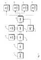
- the telecommunications system shown in Figure 1 enables the operation of both ISDN terminals 3, 4 and conventional analog telecommunications terminals 9, 10, 11, 12 on the ISDN network.
- the telecommunication system is connected via a network termination device (NT) 2 to a digital local exchange (DIVO) 2, which enables the connection to other ISDN subscribers or to other communication networks.
- the network termination device (NT) 2 thus forms the interface between the user's telecommunications system and the ISDN network.
- the network termination device (NT) 2 has a so-called U K0 interface on the network side and a so-called S 0 interface on the user side.
- Two ISDN-compatible telecommunication terminals (TA digital) 3, 4 are connected to the S 0 interface of the network termination device (NT) 2 via one ISDN connection unit (IAE) 5, 6 each. Furthermore, the network termination device (NT) 2 is followed by the interface converter (SW) 8 according to the invention, which is connected to four conventional analog telecommunication terminals (TE analog) 9, 10, 11, 12 and the conversion of the digital data arriving at the network termination device (NT) 2 in the conventional analog format or the conversion from the conventional analog format into the digital ISDN format.
- TE analog conventional analog telecommunication terminals
- the interface converter (SW) 8 is connected to an external computer (PC) 7, which among other things enables the configuration of the interface converter (SW) 8.
- One configuration option relates to the setting of the so-called terminal selection number.
- a caller of an ISDN connection can individually dial each of the connected ISDN terminals by placing the terminal selection number of the desired telecommunication terminal after the number of the ISDN connection. The call is then accepted by the terminal to which the desired terminal selection digit is assigned.
- the terminal selection number can be, for example, with ISDN terminals can be set manually using a switch.
- the conventional terminal devices 9, 10, 11, 12 connected to the interface converter (SW) do not have this option. However, when operating several conventional terminals 9, 10, 11, 12 on the interface converter (SW) 8, it is desirable to be able to dial each of these terminals individually, as in normal ISDN terminals, by means of a terminal selection number.
- the interface converter (SW) 8 therefore assigns each of the conventional terminals 9, 10, 11, 12 a terminal selection number. In the case of an incoming call, the interface converter (SW) 8 picks up the terminal selection number desired by the caller and forwards the call to the conventional terminals 9, 10, 11, 12 to which the terminal selection number desired by the caller is assigned .
- Another configuration option relates to the setting of the so-called service identifier.
- a so-called service identifier is transmitted during a call, which identifies the type of telecommunications service and, among other things, prevents a connection being established between incompatible terminals. For example, a connection between a videophone and a fax machine is not useful.
- the service identifier can be set on an ISDN device, for example by a switch.
- the interface converter (SW) 8 therefore assigns each connection for connection to a conventional analog terminal 9, 10, 11, 12 a service identifier which is transmitted when a call originates from this connection and enables the called subscriber to identify the desired telecommunication service.
- the interface converter (SW) 8 can therefore be configured by reprogramming the assignment between the connections for connection to the conventional analog terminals 9, 10, 11, 12 and the respective service identifiers via the external computer.
- the charges incurred during a connection can be monitored via the external computer (PC) 7.
- the local exchange (DIVO) 1 transmits a charge signal in the ISDN network which reflects the number of charge units incurred during a connection. This charge signal can be read out and evaluated by the external computer (PC) 7.
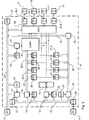
- Figure 2 shows the structure of the interface converter 8 in detail as a block diagram.
- the interface converter 8 is connected to the network termination device (NT) 2 via a data bus 23.
- this data bus 23 is used to call the number of the ISDN connection that the caller wants Transfer terminal selection number (EAZ). Since various data are transmitted via the data bus 23, the actual terminal selection digit is preceded by a message header which distinguishes the type of the following data.
- a detection unit 29 is connected to the data bus 23 and continuously compares the data stream on the data bus with the message header which announces the transmission of a terminal selection number. If such a message header is recognized, the recognition unit 29 activates, via a control line, a holding member 31, which is also connected to the data bus and reads out and temporarily stores the terminal selection number from the data bus 23.
- the interface converter 8 has four memory elements 26.1, 26.2, 26.3, 26.4 for storing the terminal selection numbers assigned to the connections.
- the terminal selection number desired by the caller and temporarily stored in the holding element 31 is then fed to a comparator unit 30 which compares the desired terminal selection number with the terminal selection numbers stored in the memory elements 26.1, 26.2, 26.3, 26.4 .
- the comparator unit 30 successively addresses the four memory elements 26.1, 26.2, 26.3, 26.4 via a control line, which then place the stored terminal selection number on a data bus 25 connected to the comparator unit 30.
- the comparator unit 30 then generates a signal which identifies the connection assigned to the desired terminal selection digit and supplies this signal to an addressing unit 34.
- the addressing unit 34 is on the one hand with the data bus 25 and on the other hand each via a conversion unit 35.1, 35.2, 35.3, 35.4 each with a connection for connection to a conventional analog terminal 9, 10, 11, 12.
- the addressing unit 34 then switches the data bus 23 through to one of the conversion units 35.1, 35.2, 35.3, 35.4 depending on the output signal of the comparator unit 30.
- the conversion units 35.1, 35.2, 35.3, 35.4 then convert the ISDN signal present on the data bus 23 into an analog signal for the conventional terminals 9, 10, 11, 12 and vice versa the analog signals of the conventional terminals 9, 10, 11, 12 into a digital ISDN signal.
- the signal emanating from this terminal is first converted into a digital ISDN signal by the conversion unit 35.1, 35.2, 35.3 or 35.4 assigned to this terminal and the addressing unit 34 fed.
- the addressing unit 34 then switches this digital ISDN signal through to the data bus 23.
- the interface converter 8 has four further memory elements 27.1, 27.2, 27.3, 27.4 for storing the service identifiers (DK) for each of the connections for connection to the conventional terminals 9, 10, 11, 12.
- DK service identifiers
- the addressing unit 34 recognizes which connection the call is originating from and sends a write signal via a control line to the memory element 27.1, 27.2, 27.3 or 27.4 assigned to this connection.
- the memory element thus activated then places the stored service identifier on a data bus 28 which is connected, inter alia, to a signal generator 33.
- the Signal generator 33 reads the service identifier from the data bus 28 and transmits it via the data bus 23 connected to the network termination device (NT) 2.
- the interface converter 8 has a serial data interface (V.24) 36 for configuring the interface converter 8 via an external computer (PC) 7.
- the computer 7 enables the programming of the memory elements 26.1, 26.2, 26.3, 26.4 to accommodate the selection of terminal devices -Numbers and the memory elements 27.1, 27.2, 27.3, 27.4 for storing the service identifiers.
- a message header is first transmitted which announces to the interface converter 8 that the following data represent a terminal selection number.
- This message header is placed on the data interface (V.24) 36 on a data bus 16, which is connected, among other things, to a recognition unit 14.
- the recognition unit 14 continuously compares the data stream on the data bus 16 with the message header which announces the transmission of a terminal selection number. If this is the case, the recognition unit 14 controls a holding element 18, which is likewise connected to the data bus 16 and reads out the intermediate device selection number from the data bus 16 and stores it temporarily.
- a service identifier is then transmitted in the same way.
- a message header is placed on the data bus 16 via the data interface (V.24) 36, which announces the transmission of a service identifier.
- the service identifier is then transmitted itself.
- a further identification unit 21 is connected to the data bus 16, which compares the data stream on the data bus 16 with the message header which announces the transmission of a service identification. If such a header from of the detection unit 21, it controls a holding member 22, which is likewise connected to the data bus 16 and temporarily stores the service identification.
- the two holding members 18 and 22 contain the terminal selection number to be programmed and the service identifier to be programmed. However, it is not yet known in which memory elements this data should be written.
- the external computer 7 therefore subsequently transmits an address signal which specifies the memory element 26.1, 26.2, 26.3, 26.4 or 27.1, 27.2, 27.3, 27.4 in which the temporarily stored data are to be written.
- an address signal which specifies the memory element 26.1, 26.2, 26.3, 26.4 or 27.1, 27.2, 27.3, 27.4 in which the temporarily stored data are to be written.
- a message header is first transmitted which announces the following transmission of the address signal.
- This message header is recognized by a recognition unit 20 connected to the data bus.
- the detection unit 20 controls a further holding element 15, which is likewise connected to the data bus 16 and then reads out the address signal from the data bus 16 and stores it temporarily.
- the buffered address signal is then fed to an addressing unit 19, which controls one of the memory elements 26.1, 26.2, 26.3 or 26.4 for storing the terminal selection digits (EAZ i ) with a read command.
- the memory element controlled in this way then reads the terminal selection digit to be programmed from the holding element 18.
- the addressing unit 19 controls one of the memory elements 27.1, 27.2, 27.3, 27.4 to store the service identifiers with a read command, which then activates the service identifier to be programmed reads from the corresponding holding member 22 and stores them permanently.
- all the memory elements 26.1, 26.2, 26.3, 26.4 or 27.1, 27.2, 27.3, 27.4 can be programmed to store the terminal selection digits or to store the service identifiers by first selecting the desired terminal selection digit and the desired service identifier and then the address of the memory element to be programmed is transmitted.
- the charges incurred during a connection can be queried via the external computer 7.
- the local exchange transmits a charge signal during a connection that reflects the number of charge units incurred during this connection.
- the interface converter 8 therefore has a further detection unit 24 which compares the data stream on the data bus 23 connected to the network termination device 2 with the pattern of a charge signal. If such a charge signal is detected by the recognition unit 24, the latter issues a read command to a holding element 17, which is also connected to the data bus 23, which then reads out the charge signal from the data bus 23 and stores it temporarily.
- the external computer 7 transmits a read command to the interface converter 8 via the data interface (V.24) 36, which is detected by a detection unit 13 connected to the data bus 16.
- the recognition unit 13 then issues a write command to the holding element 17, which contains the charge signal, via a control line.
- the cached charge signal is then placed on the data bus 16 and transmitted via the data interface (V.24) 36.
- AW network termination resistor
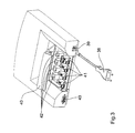
- FIG. 3 shows the interface converter described above in a perspective view.
- the interface converter is housed in a housing made of plastic, which has a recess on the top, in which a total of eight sockets 41, 42 are arranged under a flap 40 for connecting telecommunication terminals. Because of the recessed arrangement, the bushings 41, 42 are advantageously protected against damage. If no end devices are connected to the interface converter, the sockets 41, 42 can be covered by the flap 40 and then no longer disturb the visual appearance.
- sockets 41 are used - as explained in the description of FIG. 2 - to connect conventional analogue terminals such as telephones or fax machines.
- These sockets 41 are arranged side by side in a row.
- the sockets 42 for connecting these terminals are also arranged in a row behind the sockets 41 for the conventional analog terminals.
- a socket 43 is arranged in the housing for connecting an external computer, via which - as in the Description of Figure 2 explained - the interface converter can be configured.
- the charges incurred during a connection can be recorded via the external computer.
- the interface converter is connected to the network termination device via a further socket 39, also arranged in the housing.
- a transformer is arranged in the housing and can be connected to the normal power network via a power cable 38.
- the embodiment of the invention is not limited to the preferred exemplary embodiments specified above. Rather, a number of variants are conceivable which make use of the solution shown, even in the case of fundamentally different types.
Landscapes
- Engineering & Computer Science (AREA)
- Computer Networks & Wireless Communication (AREA)
- Exchange Systems With Centralized Control (AREA)
- Use Of Switch Circuits For Exchanges And Methods Of Control Of Multiplex Exchanges (AREA)
- Telephonic Communication Services (AREA)
- Amplifiers (AREA)
Applications Claiming Priority (2)
| Application Number | Priority Date | Filing Date | Title |
|---|---|---|---|
| DE29605533U DE29605533U1 (de) | 1996-03-14 | 1996-03-14 | Schnittstellenwandler |
| DE29605533U | 1996-03-14 |
Publications (2)
| Publication Number | Publication Date |
|---|---|
| EP0796029A2 true EP0796029A2 (fr) | 1997-09-17 |
| EP0796029A3 EP0796029A3 (fr) | 1999-03-31 |
Family
ID=8021667
Family Applications (1)
| Application Number | Title | Priority Date | Filing Date |
|---|---|---|---|
| EP97250077A Withdrawn EP0796029A3 (fr) | 1996-03-14 | 1997-03-14 | Transducteur d'interfaces |
Country Status (2)
| Country | Link |
|---|---|
| EP (1) | EP0796029A3 (fr) |
| DE (1) | DE29605533U1 (fr) |
Cited By (1)
| Publication number | Priority date | Publication date | Assignee | Title |
|---|---|---|---|---|
| FR2793095A1 (fr) * | 1999-04-28 | 2000-11-03 | Sagem | Terminaison numerique de reseau generalisee adaptable a un reseau temporairement analogique |
Family Cites Families (11)
| Publication number | Priority date | Publication date | Assignee | Title |
|---|---|---|---|---|
| EP0312573B1 (fr) * | 1987-05-01 | 1993-09-01 | Digital Equipment Corporation | Bus de carte mere |
| DE3738896A1 (de) * | 1987-11-17 | 1989-05-24 | Standard Elektrik Lorenz Ag | Gehaeuse zur aufnahme von elektrischen baugruppen |
| DE3823913A1 (de) * | 1988-07-14 | 1990-01-18 | Siemens Ag | Komunikationssystem mit vorgegebenen, von einer kommunikationsanlage durch informationsuebermittlung bestimmte und gesteuerte funktionen versehenen kommunikationsendeinrichtungen |
| DE3923125A1 (de) * | 1989-07-13 | 1991-01-24 | Standard Elektrik Lorenz Ag | Universelle isdn-teilnehmeranschlussbaugruppe |
| AT396535B (de) * | 1990-06-13 | 1993-10-25 | Semcotec Handel | Nachrichtenübertragungssystem, insbesondere telefonsystem |
| DE4125362C2 (de) * | 1991-07-31 | 1995-10-12 | Siemens Ag | Anordnung zum Anschalten analoger Kommunikationsendgeräte an digitale Teilnehmeranschlußeinrichtungen eines Kommunikationssystems |
| SE9103382L (sv) * | 1991-11-15 | 1993-05-16 | Televerket | Anordning foer anslutningsanpassning till digitalt telekommunikationsnaet |
| US5305312A (en) * | 1992-02-07 | 1994-04-19 | At&T Bell Laboratories | Apparatus for interfacing analog telephones and digital data terminals to an ISDN line |
| DE4302723A1 (de) * | 1993-02-01 | 1994-08-04 | Deutsche Bundespost Telekom | Vorsatzgerät zum Anschalten von analogen Telekommunikationsanlagen mit Dateneingang und ISDN-Datenendgeräten an das öffentliche ISDN-Netz |
| US5483530A (en) * | 1993-12-16 | 1996-01-09 | International Business Machines Corporation | System and method for communicating with digital and analog devices via a single digital interface |
| US6546442B1 (en) * | 1995-10-30 | 2003-04-08 | International Business Machines Corporation | Communications adapter having analog and digital interfaces for communications with remote systems |
-
1996
- 1996-03-14 DE DE29605533U patent/DE29605533U1/de not_active Expired - Lifetime
-
1997
- 1997-03-14 EP EP97250077A patent/EP0796029A3/fr not_active Withdrawn
Cited By (1)
| Publication number | Priority date | Publication date | Assignee | Title |
|---|---|---|---|---|
| FR2793095A1 (fr) * | 1999-04-28 | 2000-11-03 | Sagem | Terminaison numerique de reseau generalisee adaptable a un reseau temporairement analogique |
Also Published As
| Publication number | Publication date |
|---|---|
| DE29605533U1 (de) | 1997-07-17 |
| EP0796029A3 (fr) | 1999-03-31 |
Similar Documents
| Publication | Publication Date | Title |
|---|---|---|
| DE69434646T2 (de) | Netz mit digitalen und analogen Ausgängen | |
| DE4440545C2 (de) | Verfahren zur Verarbeitung von Rufen bei einer Telefonanlage | |
| DE2747417C2 (fr) | ||
| DE19542122B4 (de) | Lokales Kommunikations-Serversystem | |
| DE2902644A1 (de) | Verfahren und vorrichtung zur verarbeitung von verbindungs-anforderungssignalen in einem fernmeldesystem | |
| EP0440063A2 (fr) | Central privé à large bande | |
| EP0392141A2 (fr) | Central numérique de télécommunication | |
| EP0623267B1 (fr) | Dispositif modulaire telephonique d'abonne | |
| EP0295470A2 (fr) | Méthode pour un dispositif de commutation commandé par calculateur, en particulier pour un central téléphonique à touches avec la possibilité de transfert d'appel | |
| EP1203497B1 (fr) | Procede d'actualisation de donnees concernant un abonne d'un reseau de telecommunications | |
| DE19630456B4 (de) | ISDN-Telefon | |
| EP0796029A2 (fr) | Transducteur d'interfaces | |
| DE60019823T2 (de) | Telekommunikationsnetz mit einer ferngesteuerten Leitungs-mehrschnittstelle und Telekommunikationsverfahren | |
| EP0153753A2 (fr) | Méthode pour un central de télécommunication, en particulier pour central téléphonique privé à assignation de fonctions d'opération spéciales aux postes terminaux | |
| DE19548296C2 (de) | Bidirektionaler Datenaustausch (Protokoll) zwischen einer TK-Anlage und einer Endeinrichtung | |
| WO1993005606A1 (fr) | Dispositif de telecommunications | |
| DE2459555C2 (de) | Verfahren zur Steuerung einer speicherprogrammgesteuerten Zeitmultiplex-Vermittlungsanlage | |
| EP0923220A2 (fr) | Méthode de gestion de données individuelles d'abonné d'un appareil de télécommunication | |
| DE3131343C2 (fr) | ||
| DE4232120A1 (de) | System fuer die interfaceverschaltung von telefonsets mit einem centrexsystem | |
| DE3610730A1 (de) | Einrichtung fuer eine zweit-nebenstellenanlage | |
| DE4113366C2 (fr) | ||
| DE19534746A1 (de) | Schnittstelleneinrichtung zur Verbindung eines Computers mit dem ISDN-Netz | |
| DE2811006C2 (de) | Verfahren zur Steuerung von Funktionsabläufen in einem zentralgesteuerten Fernsprechvermittlungssystem, insbesondere in einer zentralgesteuerten Fernsprechnebenstellenanlage, mit Zuteilung von Leitungen | |
| DE19741770C1 (de) | Kommunikationssystem und entsprechendes Verfahren |
Legal Events
| Date | Code | Title | Description |
|---|---|---|---|
| PUAI | Public reference made under article 153(3) epc to a published international application that has entered the european phase |
Free format text: ORIGINAL CODE: 0009012 |
|
| AK | Designated contracting states |
Kind code of ref document: A2 Designated state(s): AT BE CH DE ES FI FR GB IT LI NL PT |
|
| RIN1 | Information on inventor provided before grant (corrected) |
Inventor name: OPPERMANN THOMAS Inventor name: KLOEPPER DIETMAR Inventor name: HUNFELD JOHANN Inventor name: MEYER ANDREAS |
|
| PUAL | Search report despatched |
Free format text: ORIGINAL CODE: 0009013 |
|
| AK | Designated contracting states |
Kind code of ref document: A3 Designated state(s): AT BE CH DE ES FI FR GB IT LI NL PT |
|
| 17P | Request for examination filed |
Effective date: 19990923 |
|
| STAA | Information on the status of an ep patent application or granted ep patent |
Free format text: STATUS: THE APPLICATION IS DEEMED TO BE WITHDRAWN |
|
| 18D | Application deemed to be withdrawn |
Effective date: 20031001 |