EP0796053B1 - Zusammenklappbare tür für geschirrspülmaschine - Google Patents
Zusammenklappbare tür für geschirrspülmaschine Download PDFInfo
- Publication number
- EP0796053B1 EP0796053B1 EP96930513A EP96930513A EP0796053B1 EP 0796053 B1 EP0796053 B1 EP 0796053B1 EP 96930513 A EP96930513 A EP 96930513A EP 96930513 A EP96930513 A EP 96930513A EP 0796053 B1 EP0796053 B1 EP 0796053B1
- Authority
- EP
- European Patent Office
- Prior art keywords
- door
- washing chamber
- panel
- handle
- upper panel
- Prior art date
- Legal status (The legal status is an assumption and is not a legal conclusion. Google has not performed a legal analysis and makes no representation as to the accuracy of the status listed.)
- Expired - Lifetime
Links
- 238000005406 washing Methods 0.000 claims description 71
- 230000008878 coupling Effects 0.000 claims description 16
- 238000010168 coupling process Methods 0.000 claims description 16
- 238000005859 coupling reaction Methods 0.000 claims description 16
- XLYOFNOQVPJJNP-UHFFFAOYSA-N water Substances O XLYOFNOQVPJJNP-UHFFFAOYSA-N 0.000 claims description 8
- 238000007689 inspection Methods 0.000 claims description 5
- 235000014510 cooky Nutrition 0.000 description 5
- 230000007246 mechanism Effects 0.000 description 5
- 230000004048 modification Effects 0.000 description 2
- 238000012986 modification Methods 0.000 description 2
- 238000009428 plumbing Methods 0.000 description 2
- 239000011521 glass Substances 0.000 description 1
- 238000003780 insertion Methods 0.000 description 1
- 230000037431 insertion Effects 0.000 description 1
- 239000007921 spray Substances 0.000 description 1
Images





Classifications
-
- A—HUMAN NECESSITIES
- A47—FURNITURE; DOMESTIC ARTICLES OR APPLIANCES; COFFEE MILLS; SPICE MILLS; SUCTION CLEANERS IN GENERAL
- A47L—DOMESTIC WASHING OR CLEANING; SUCTION CLEANERS IN GENERAL
- A47L15/00—Washing or rinsing machines for crockery or tableware
- A47L15/42—Details
-
- A—HUMAN NECESSITIES
- A47—FURNITURE; DOMESTIC ARTICLES OR APPLIANCES; COFFEE MILLS; SPICE MILLS; SUCTION CLEANERS IN GENERAL
- A47L—DOMESTIC WASHING OR CLEANING; SUCTION CLEANERS IN GENERAL
- A47L15/00—Washing or rinsing machines for crockery or tableware
- A47L15/0076—Washing or rinsing machines for crockery or tableware of non-domestic use type, e.g. commercial dishwashers for bars, hotels, restaurants, canteens or hospitals
- A47L15/0081—Washing or rinsing machines for crockery or tableware of non-domestic use type, e.g. commercial dishwashers for bars, hotels, restaurants, canteens or hospitals with vertical sliding closing doors, e.g. hood-type dishwashers
Definitions
- the present invention relates to warewashing machines and, particularly, to a novel slidable door for a warewashing machine which permits the warewashing machine to be used for washing conventional wares as well as oversized wares.
- Standard size warewashers can not accommodate oversized wares because the area of access to the washing chamber and the washing chamber, itself, are too small to allow oversized utensils to be fitted into the washing chamber.
- a standard warewasher has a washing chamber having an opening with dimensions of about 55.9 cm (22 inches) wide and about 43.2 cm (17 inches) high.
- a warewasher as the one described in US 3 049 391, having a washing chamber and chamber doors sized for accepting oversized items such as utensils, baking pans, cookie sheets and large sized mixing bowls.
- This warewasher must have dimensions which fit into the same square foot floor area as a standard warewasher so that it can be used as a replacement for the standard warewasher without requiring that the kitchen, in which the warewasher is being used, be reconfigured.
- a disadvantage with merely increasing the size of the door panel to allow for loading of such oversized wares is that, as the conventional door panels are conventionally slid upward to provide access to a washing chamber, increasing the size of these panels would, in some situations, be limited by the height of the kitchen ceiling.
- This present invention is directed to a warewasher which can be used to wash not only conventional wares such as plates, glasses and tableware but also oversized wares such as utensils, baking pans, cookie sheets and large sized mixing bowls.
- the doors of this invention are particularly suited for use with a warewasher having a larger than standard size washing chamber, and are designed to allow this larger capacity warewasher to occupy substantially the same kitchen space as a conventional warewasher.
- the doors of this invention can be used as either inspection doors or as access doors for such a warewasher.
- the warewasher doors of this invention comprises two slidable panels, a lower panel and an upper panel. Both panels are slidably mounted in vertical tracks on vertical sides of a rectangular opening into the washing chamber of the warewasher.
- the lower panel is mounted so that it slides in front of the upper panel.
- a first flange extends from the upper panel and is adapted to rest on the top of the warewasher when the door is closed, to prevent water from flowing out of the warewasher and to also serve as a downward motion stop for the upper panel.
- a second flange extends from the upper panel toward the lower panel, and a third flange extends from the lower panel to engage and overlap the second flange of the upper panel to provide a seal which prevents water from flowing between the two panels when the door is closed.
- the lower panel also includes a bracket mounted on its inside which engages the lower surface of the upper panel when the lower panel is raised to a predetermined height. This engagement allows the lower panel to lift the upper panel creating an additional area of clearance equal in size to the area of the upper panel to allow insertion of oversized wares and utensils into the washing chamber.
- the present invention also includes a pivoted handle designed to facilitate easy opening of the warewasher doors.
- the end portion of the handle has a downward curving arcuate shape which allows it to be easily grasped when the door is either in the open or closed position.
- the handle includes three sections: an arcuate section which leads into a straight section which terminates in a transverse section.
- the handle pivots about a pin mounted on the washing chamber of the warewasher.
- the door is opened by grasping the arcuate section and lifting the arcuate section of the handle toward the top of the machine. This motion causes the handle to pivot about the pivot pin to cause the door to open.
- the operator can easily grasp the handle by the arcuate section which curves down well within reach of the operator, allowing the operator to easily pull the door back to a closed position.
- the two door warewasher is designed to be placed in a corner for use and has doors on two adjacent sides.
- the three door warewasher is designed for use when placed against a wall so that the back side of the warewasher faces the wall.
- This model has doors on three adjacent sides.
- the dishes are loaded into a door on one side of the warewasher and removed from a door on the opposite side of the warewasher.
- the third door, on the front of the warewasher can be opened to inspect the dishes and the washing chamber, or to load or remove items to or from the washing chamber.
- Fig. 1 presents a front view of a three-door warewasher 10 which generally comprises a base 12, a washing chamber 14, a control means 16, a motor and pump assembly 18 and plumbing 20.
- the washing chamber 14 and the control means 16 are mounted on the base 12.
- the control means 16 controls the operations of the warewasher 10.
- the motor and pump assembly 18 is mounted on the base 12 beneath the washing chamber 14.
- the pump circulates water in the washing chamber 14 and the motor drives the pump.
- Plumbing 20 is mounted on the rear and top of the washing chamber 14 and extends from the top of the washing chamber 14.
- a front, "inspection" door 22 of the present invention is slidably mounted on the front of washing chamber 14 to provide access to a rectangular opening 23 on the front of the washing chamber; and two side doors 30 (See Fig.
- a front handle 24, for opening and closing the front door 22, is mounted on the outside of the front door 22, and a pivoting side handle 32 for opening the side doors 30 is mounted to the warewasher and to the side doors as will be described in detail below.
- the side doors 30 are slidably mounted on each side of washing chamber 14. This is such that dirty wares can be fed into one side of the warewasher, through one side door 30, and such that the cleaned wares can be taken from the opposite side of the warewasher, through the other side door 30.
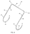
- the pivoting handle 32 for opening and closing the side doors 30, is mounted on the warewasher and comprises a pair of arcuate sections 34 (one shown), a pair of straight sections 36 (one shown) and a transverse section 38.
- the handle 32 is pivotally mounted on washing chamber 14 by a pair of pivot mechanisms 40 (see also Fig. 1), and is coupled to the side doors 30 by a pair of flat link bars 42 (one shown).
- a water tank 50 is located beneath the washing chamber 14.
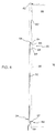
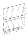
- Fig. 3 presents a perspective view of the front door 22 of this invention in the closed position as seen from the inside of the washing chamber 14; and Fig. 4 presents an end view of the front door 22 in the closed position.
- the front door 22 comprises a lower panel 52, and an upper panel 60 positioned above the lower panel 52.
- the lower and upper panels 52, 60 are slidably mounted in vertical tracks 26 fastened to the vertical sides of the rectangular opening 23.
- the lower panel 52 is mounted in front of the upper panel 60 in the tracks 26.
- a flange 54 extends inwardly from the upper edge of the lower panel 52 and is adapted to slide along the outer surface upper panel 60.
- An inwardly extending flange 62 and an outwardly extending flange 64 extend from the upper and lower horizontal edges of upper panel 60, respectively.
- the flange 62 rests over the top 65 of the washing chamber 14 to prevent water overflow from the washing chamber 14; and the flange 54 on the lower panel 52 engages and overlies the flange 64 to prevent water from escaping from between the lower and upper panels 52, 60.
- the flange 64 is adapted to slide along the inner surface of the lower panel 52 as the front door 22 is being opened or closed.
- a door stop 56 having an inwardly extending shelf portion 57, is mounted on the inside of lower panel 52 by fasteners 58; a bracket 66 is mounted on the inside surface of the upper panel 60; and an inwardly extending door stop 68 is mounted to the bracket 66 by fasteners 69.
- the front door 22 can be opened further to an advanced open position which provides a second area of access to washing chamber 14, larger than the first area of access.
- the operator continues to lift upwardly on the handle 24 such that the door stop 56, engaged with the flange 64, translates upward force to the upper panel 60, causing both the upper panel 60 and the lower panel 52 to slide upwardly in the tracks 26.
- the door stop 56 is engaged with the flange 64 of the upper panel 60 to maintain the upper panel 60 in this advanced open position.
- the shelf portion 57 of door stop 56 extends inwardly beyond the flange 64 such that it can catch onto the upper edge of washing chamber 14 when the door stop 56 is lifted to the height of the edge of the washing chamber. This contact causes the upward motion of the upper and lower panels 60, 52 to stop and, at this point, the front door 22 is at its maximum advanced open position.
- the bracket 66 and door stop 68 are provided on the upper panel 60 to prevent the removal of the upper panel 60 from the warewasher 10.
- the door stop 68 on the bracket 66 is adapted to engage the top 65 of the washing chamber 14 of the warewasher 10, thus preventing the upper panel 60 from being slid above the warewasher 10, thereby securing the upper panel within the tracks 26. If upper panel 60 were removed and the lower panel 52 of door 22 were to be subsequently shut, the warewasher 10 would spray water over the area in which the warewasher 10 is used. It should also be apparent that since the upper panel 60 is secured in the tracks 26, then lower panel 52 is also prevented from being slid above the warewasher due to the engagement of the door stop 56 on the flange 64 with the bottom of the upper panel 60.
- the addition of the upper panel 60 to the front door 22 creates an area of access to the washing chamber 14, which, when the front door 22 is opened to an advanced position, can exceed the area of access to the washing chambers of a prior art warewasher by the height of the upper panel 60.
- the washing chamber 14 has a height which is about 11 inches higher than the height of a conventional warewasher. This increased height produces a correspondingly increased area of access to the washing chamber 14, which allows loading of oversized items, such as utensils, baking pans, cookie sheets and large sized mixing bowls into the washing chamber 14.
- the volume of the washing chamber 14 is effectively increased without producing a corresponding increase in the floor space area that base 12 of warewasher 10 occupies; and furthermore, because the upper and lower panels 60, 52 collapse together as the front door 22 is being opened, the height of the ceiling does not restrict opening the front door 22 to its advanced open position.
- the side doors 30 are also preferably constructed and operate substantially identical to the front door 22, having collapsible lower and upper panels 52', 60' which allow for intermediate and advanced opening capabilities.
- the warewasher 10 includes the pivoting side handle 32 designed to facilitate easy opening and closing of the side doors 30. Therefore, other than for the operation of the pivoting handle 32 as will be given below, the above description of the structure and operation of the front door 22 will suffice to adequately describe the structure and operation of the side doors 30.
- the handle 32 includes a pair of arcuate sections 34, a pair of straight sections 36 and a transverse section 38.
- Transverse section 38 bridges between aftward ends 35 of parallel straight sections 36, such that the handle is substantially u-shaped; and the forward ends 37 of the straight sections 36 tangentially adjoin the downward curving arcuate sections 34.
- An inwardly extending boss 80 is formed on each straight section 36 of the handle 32, for pivotally mounting the handle onto the washing chamber 14 of the warewashing machine 10 by means of a pivot pin mechanism 40, which engages with the bosses 80 as is described in detail below.
- the transverse section 38 of the pivoting handle 32 extends across the rear of washing chamber 14 and adjoins the parallel straight section 36 on the opposite sides of washing chamber 14.
- the handle 32 is coupled to the side doors 30 by means of a pair of flat link bars 42.
- Each link bar 42 is coupled to the side doors 30 by a pivotal coupling 44 at a first end of the link bar, and each link bar is also coupled to the handle 32 by a pivotal coupling 46 at an opposite end of the link bar.
- the pivotal couplings 46 are located along the handle 32 approximately at the forward ends 37 of the straight sections 36; and preferably, the pivotal couplings 44 are located near the bottom-center of the lower door panels 52'.
- the link bars 42 and pivotal couplings 44, 46 allow the handle 32 to be coupled to the doors 30 while allowing to arcuate sections 34 of the handles to both pivot and translate with respect to the doors as the doors are being vertically raised or lowered.
- the handle can be pivotally attached to a coupling which is, in turn, slidably mounted in a groove in the lower panel 52' of the door.
- a conventional counterbalance spring 82 is coupled at one end to the transverse portion 38 of the handle 32, and is coupled at its other end to a rod 84 which is secured to a flange 85 extending across the rear of base 12 of warewasher 10.
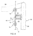
- the pivot pin mechanism 40 comprises a pin 70 and a boss 80.
- the pin 70 is welded on a plate 72 which is attached to the washing chamber 14 by means of fasteners 74.
- the pin 70 extends through an aperture 76 in the washing chamber 14.
- the boss 80 is welded onto the straight portion 36 of the handle 32.
- the pin 70 fits into the boss 80 to pivotally mount the handle 32 to the washing chamber 14.
- the operator grasps the handle 32 by one of the arcuate sections 34 and lifts upwardly such that handle 32 rotates about the pivot pin mechanisms 40 (clockwise in Fig. 2) and, in turn, simultaneously lifts both side doors 30 by means of the link rods 42.
- the counterbalance spring 82 assists the operator in lifting handle 32 against gravitational forces, and acts to maintain the doors 30 in an open position, against gravitational forces, once they have been opened.
- an arcuate section 34 having a radius ranging from approximately 10.2 cm (four inches) to 20.3 cm (eight inches) (4"-8") provides the preferred positioning and reach capabilities for the handle 32 in all opened and closed positions of the door; while an arcuate section 34 having a radius of approximately 17.8 cm (seven inches) (7") provides the optimum positioning and reach capabilities for the handle 32.
- the operator closes the doors 30 by grasping the handle 32, in or near the arcuate section 34, and by pulling it down to overcome the force of the counterbalance spring 82.
- This causes the handle 32 to rotate about the pivot pin mechanisms 40 (counter-clockwise in Fig. 2) and, in turn, simultaneously causes the link rods 42 to slide down both side doors 30.
- pivoting handle similar to pivoting handle 32, for a single warewasher door.
- Such an alternative handle would include an arcuate section and a straight section similar to that of the pivoting handle 32; would be pivotally coupled to the warewasher near the aft end of the straight section similar to the pivoting handle 32; and would be translationally and pivotally coupled to the warewasher door via a link bar similar to that of the pivoting handle 32.
- collapsible doors of this invention can be used on both the two door and the three door warewasher.
- the collapsible doors of this invention may also be used on a single door warewasher with little or no modification.
- collapsible warewasher doors of this invention can be used either as inspection doors or access doors to the washing chamber. Whether used as an inspection door or as an access door, its function and operation are be the same as they are described above.
Landscapes
- Sanitary Device For Flush Toilet (AREA)
- Washing And Drying Of Tableware (AREA)
- Residential Or Office Buildings (AREA)
- Ladders (AREA)
- Cleaning By Liquid Or Steam (AREA)
Claims (14)
- Geschirrspülmaschine (10) umfassend:worin die Tür (22) durch Anheben der unteren Platte (52) derart, daß der Türanschlag (68) die untere Fläche der oberen Platte (60) berührt, zu einer Zwischenposition zu öffnen ist, wodurch ein erstes Zugangsgebiet zur Waschkammer (14) bereitgestellt wird, undeine Basis (12),eine auf der Basis (12) ruhende Waschkammer (14), wobei die Waschkammer (14) mindestens eine im allgemeinen rechteckige Öffnung (23) mit zwei vertikalen Seiten an einer ersten Seite der Waschkammer (14) aufweist,vertikale Schienen (26), die an jede vertikale Seite der Öffnung (23) montiert sind, undeine Tür (22) zum Liefem eines Zugangs zur Öffnung (23), wobei die Tür (22) eine untere Platte (52), mit einem oberen Ende (54), einem unteren Ende, einer innere n Fläche und einer äußeren Fläche, die in den vertikalen Schienen (26) verschiebbar montiert ist,einen Griff (24), der an der äußeren Fläche der unteren Platte (52) montiert ist,eine obere Platte (60), die in den vertikalen Schienen (26) innerhalb der unteren Platte (52) verschiebbar montiert ist und ein oberes Ende, ein unteres Ende, eine untere Fläche, eine innere Fläche und einen ersten Flansch (62) aufweist, der sich vom oberen Ende der oberen Platte (60) für einen Eingriff mit einer oberen Fläche (65) der Waschkammer (14) und zum Abhalten der oberen Platte (60) vom Gleiten unter der oberen Fläche (65) der Waschkammer (14) vom oberen Ende der oberen Platte (60) nach innen erstreckt, undeinen Türanschlag (68) enthält, der an der inneren Fläche der unteren Platte (52), in der Nähe des unteren Endes der unteren Platte (52) für einen Eingriff mit der unteren Fläche der oberen Platte (60) montiert ist,
worin die Tür (22) durch weiteres Anheben der unteren Platte (52) derart, daß der Türanschlag (68), der mit der unteren Fläche der oberen Platte (60) in Eingriff steht, bewirkt, daß die obere Platte (60) gleichzeitig angehoben wird, zu einer vorgerückten Position zu öffnen ist, wodurch ein zweites Zugangsgebiet zur Waschkammer (14) bereitgestellt wird, das größer als das erste Zugangsgebiet ist. - Geschirrspülmaschine nach Anspruch 1, dadurch gekennzeichnet, daß die Tür ferner enthält:einen zweiten Flansch, der sich vom oberen Ende der unteren Platte nach innen erstreckt, undeinen dritten Flansch, der sich vom unteren Ende der oberen Platte nach außen erstreckt, wobei der zweite Flansch zum Eingreifen des dritten Flansches und zum Liefern einer Abdichtung zwischen den oberen und den unteren Platten, wenn die Tür geschlossen ist, geeignet ist.
- Geschirrspülmaschine nach Anspruch 2, dadurch gekennzeichnet, daß der erste Flansch dafür geeignet ist, Wasser am Austreten aus der Waschkammer, wenn die Tür geschlossen ist, zu hindem.
- Geschirrspülmaschine nach Anspruch 3, dadurch gekennzeichnet, daß die Tür außerdem einen zweiten Türanschlag enthält, der mit der inneren Fläche der oberen Platte gekoppelt ist, um zu verhindern, daß die obere Platte aus der Geschirrspülmaschine entfernt wird.
- Geschirrspülmaschine nach Anspruch 1, dadurch gekennzeichnet, daß der Griff enthält:wobei der Griff, durch eine erste Kupplung in der Nähe des hinteren Endes des gradlinigen Abschnittes, schwenkbar mit dem Geschirrspüler gekoppelt ist, und der Griff, durch eine zweite Kupplung, mit der Tür in der Nähe des vorderen Endes des gradlinigen Abschnittes schwenkbar und translatorisch gekoppelt ist.einen gradlinigen Abschnitt mit einem hinteren Ende und einem vorderen Ende, undeinen abwärts gekrümmten bogenförmigen Abschnitt, der sich vom vorderen Ende des gradlinigen Abschnittes tangential erstreckt,
- Geschirrspülmaschine nach Anspruch 5, ferner enthaltend eine Ausgleichsfeder, die zum Unterstützen des Schwenkens des Griffes um die erste Kupplung, und wiederum, Öffnen der Tür zwischen dem Griff und dem Geschirrspüler angekoppelt ist.
- Geschirrspülmaschine nach Anspruch 5, dadurch gekennzeichnet, daß die zweite Kupplung eine Verbindungsstange enthält, die schwenkbar mit dem Griff in der Nähe des vorderen Endes des gradlinigen Abschnittes gekoppelt ist und mit der Tür in der Nähe der unteren Mitte der unteren Platte schwenkbar gekoppelt ist.
- Geschirrspülmaschine nach Anspruch 5, dadurch gekennzeichnet, daß der bogenförmige Abschnitt einen Radius von näherungsweise vier bis acht Zoll aufweist.
- Geschirrspülmaschine nach Anspruch 6, dadurch gekennzeichnet, daß der bogenförmige Abschnitt einen Radius von näherungsweise sieben Zoll aufweist.
- Geschirrspülmaschine nach Anspruch 1, dadurch gekennzeichnet, daß die Tür eine Schauklappe oder eine Zugangstür für eine Geschirrspülmaschine ist.
- Geschirrspülmaschine (10) umfassend:worin jede Tür (22) durch Anheben der unteren Platte (52) derart, daß der Türanschlag (68) die untere Fläche der oberen Platte (60) berührt, zu einer Zwischenposition zu öffnen ist, wodurch ein erstes Zugangsgebiet zur Waschkammer (14) bereitgestellt wird, undeine Basis (12),eine auf der Basis (12) ruhende Waschkammer (14), wobei die Waschkammer eine erste und eine zweite im allgemeinen rechteckige Öffnung (23) an gegenüberliegenden Seiten der Waschkammer (14) aufweist, wobei jede Öffnung (23) zwei vertikale Seiten aufweist,vertikale Schienen (26), die an jede vertikale Seite der ersten und zweiten Öffnungen (23) montiert sind,erste und zweite Türen (22) zum Liefern eines Zugangs zu den ersten und den zweiten Öffnungen (23), wobei jede Tür (22)eine untere Platte (52) mit einem oberen Ende (54), einem unteren Ende, einer inneren Fläche und einer äußeren Fläche, die in den vertikalen Schienen (26) verschiebbar montiert ist,einen Griff (24) der an die äußere Fläche der unteren Platte (52) montiert ist,eine obere Platte (60), die in den vertikalen Schienen (26) innerhalb der unteren Platte (52) verschiebbar montiert ist, mit einem oberen Ende, eine unteren Ende, einer unteren Fläche, einer inneren Fläche und einem ersten Flansch (62), der sich vom oberen Ende der oberen Platte (60) für einen Eingriff mit einer oberen Fläche (65) der Waschkammer (14) und zum Abhalten der oberen Platte (60) vom Gleiten unter der oberen Fläche (65) der Waschkammer (14) nach innen erstreckt, und einen Türanschlag (68) enthält, der an der inneren Fläche der unteren Platte (52) in der Nähe des unteren Endes der unteren Platte (52) für einen Eingriff mit der unteren Fläche der oberen Platte (60) montiert ist,
worin jede Tür (22) durch weiteres Anheben der unteren Platte (52) derart, daß der Türanschlag (68), der mit der unteren Fläche der oberen Platte (60) in Eingriff steht, bewirkt, daß die obere Platte (60) gleichzeitig angehoben wird, zu einer vorgerückten Position zu öffnen ist, wodurch ein zweites Zugangsgebiet zur Waschkammer (14) bereitgestellt wird, das größer als das erste Zugangsgebiet ist. - Geschirrspülmaschine nach Anspruch 11, dadurch gekennzeichnet, daß jeder Griff enthält;einen gradlinigen Abschnitt mit einem hinteren Ende und einem vorderen Ende, undeinen abwärts gekrümmten bogenförmigen Abschnitt, der sich vom vorderen Ende des gradlinigen Abschnitts tangential erstreckt,wobei jeder Griff, durch eine erste Kupplung, in der Nähe des hinteren Endes des gradlinigen Abschnittes mit dem Geschirrspüler schwenkbar gekoppelt ist, undjeder Griff, durch eine zweite Kupplung, mit der Tür in der Nähe des vorderen Endes des gradlinigen Abschnittes schwenkbar und translatorisch gekoppelt ist,wobei jede zweite Kupplung eine Verbindungsstange enthält, die mit ihrem korrespondierenden Griff in der Nähe des vorderen Endes des gradlinigen Abschnitt schwenkbar gekoppelt ist und mit ihrer korrepondierenden Tür in der Nähe der unteren Mitte der unteren Platte schwenkbar gekoppelt ist.
- Geschirrspülmaschine nach Anspruch 12, femer umfassend:eine Querstange, die hinter der Waschkammer positioniert und mit den hinteren Enden der gradlinigen Abschnitte der Griffe der ersten und zweiten Türen gekoppelt ist,wobei die ersten und zweite Türen sich simultan öffnen und schließen werden.
- Geschirrspülmaschine nach Anspruch 13, ferner umfassend eine Ausgleichsfeder, die zwischen der Querstange und dem Geschirrspüler zum Unterstützen des Schwenkens der Griffe um die ersten Kupplungen und wiederum, Öffnen der ersten und zweiten Türen ankoppelt ist.
Applications Claiming Priority (5)
| Application Number | Priority Date | Filing Date | Title |
|---|---|---|---|
| US359295P | 1995-09-12 | 1995-09-12 | |
| US3592P | 1995-09-12 | ||
| US08/632,556 US5630438A (en) | 1995-09-12 | 1996-04-15 | Collapsible door for a warewasher |
| US632556 | 1996-04-15 | ||
| PCT/US1996/013079 WO1997009921A1 (en) | 1995-09-12 | 1996-08-12 | Collapsible door for a warewasher |
Publications (3)
| Publication Number | Publication Date |
|---|---|
| EP0796053A1 EP0796053A1 (de) | 1997-09-24 |
| EP0796053A4 EP0796053A4 (de) | 2000-05-03 |
| EP0796053B1 true EP0796053B1 (de) | 2003-04-02 |
Family
ID=26671939
Family Applications (1)
| Application Number | Title | Priority Date | Filing Date |
|---|---|---|---|
| EP96930513A Expired - Lifetime EP0796053B1 (de) | 1995-09-12 | 1996-08-12 | Zusammenklappbare tür für geschirrspülmaschine |
Country Status (8)
| Country | Link |
|---|---|
| US (1) | US5630438A (de) |
| EP (1) | EP0796053B1 (de) |
| JP (1) | JPH10509087A (de) |
| KR (1) | KR100423473B1 (de) |
| AU (1) | AU697276B2 (de) |
| CA (1) | CA2202666C (de) |
| DE (1) | DE69627126T2 (de) |
| WO (1) | WO1997009921A1 (de) |
Cited By (1)
| Publication number | Priority date | Publication date | Assignee | Title |
|---|---|---|---|---|
| DE102005034408A1 (de) * | 2005-07-22 | 2007-02-01 | Meiko Maschinenbau Gmbh & Co. Kg | Flügeltür für Geschirrspülmaschinen |
Families Citing this family (14)
| Publication number | Priority date | Publication date | Assignee | Title |
|---|---|---|---|---|
| CA2246402C (en) * | 1997-09-05 | 2001-02-06 | Premark Feg L.L.C. | Door/sill interface for a warewasher |
| DE19931877A1 (de) * | 1999-07-09 | 2001-01-11 | Winterhalter Gastronom Gmbh | Hebemechanismus |
| US6338352B1 (en) * | 1999-08-12 | 2002-01-15 | Maytag Corporation | Self-rising door handle |
| US7021322B2 (en) * | 2003-12-25 | 2006-04-04 | Premark Feg L.L.C. | Warewash machine with wrap-around hood and multi-position splash guard, and drip flange for warewash machine |
| US20060037631A1 (en) * | 2004-08-20 | 2006-02-23 | Kramer Steven H | Warewash machine and related door construction |
| ES2385835T3 (es) * | 2005-04-27 | 2012-08-01 | Hoshizaki Denki Kabushiki Kaisha | Lavavajillas |
| US20070131258A1 (en) * | 2005-12-13 | 2007-06-14 | Electrolux Home Products, Inc. | Dishwasher including a first door and a second door |
| US8500917B2 (en) * | 2007-02-09 | 2013-08-06 | Premark Feg L.L.C. | Warewasher and associated door construction |
| US9618211B2 (en) * | 2014-01-27 | 2017-04-11 | Illinois Tool Works Inc. | Commercial cooking oven with removable door assembly |
| US9962059B2 (en) | 2014-05-08 | 2018-05-08 | Illinois Tool Works Inc. | Warewasher wash arm filter arrangement |
| US10506908B2 (en) | 2016-07-22 | 2019-12-17 | Illinois Tool Works Inc. | Batch-type warewasher with energy retaining curtain |
| EP3668364B1 (de) | 2017-08-14 | 2021-10-06 | Illinois Tool Works Inc. | Geschirrspülmaschine und zugehörige haubenkonstruktion |
| EP3727123B1 (de) | 2017-12-21 | 2021-10-06 | Illinois Tool Works, Inc. | Geschirrspülmaschine mit dampfextraktionseinheit |
| US11963649B2 (en) | 2017-12-21 | 2024-04-23 | Illinois Tool Works Inc. | Warewash machine with vapor extraction unit |
Family Cites Families (20)
| Publication number | Priority date | Publication date | Assignee | Title |
|---|---|---|---|---|
| US3125105A (en) * | 1964-03-17 | Fig-z a | ||
| FR388630A (fr) * | 1908-03-19 | 1908-08-18 | August Louis Renaud | Système de chauffage économique de fours de boulangerie et patisserie |
| US2063746A (en) * | 1930-11-03 | 1936-12-08 | Hobart Mfg Co | Washing machine |
| US2073521A (en) * | 1931-01-17 | 1937-03-09 | Hobart Mfg Co | Washing machine |
| US2158904A (en) * | 1933-05-22 | 1939-05-16 | Hobart Mfg Co | Washing machine |
| US2128008A (en) * | 1934-10-12 | 1938-08-23 | Hobart Mfg Co | Washing machine |
| US2229663A (en) * | 1936-10-24 | 1941-01-28 | Hobart Mfg Co | Washing machine |
| US2217705A (en) * | 1937-05-05 | 1940-10-15 | Hobart Mfg Co | Washing machine |
| US2707961A (en) * | 1949-10-11 | 1955-05-10 | Hobart Mfg Co | Dishwasher |
| US2850025A (en) * | 1956-02-03 | 1958-09-02 | Bond William | Dishwashing machine |
| US2947311A (en) * | 1956-07-19 | 1960-08-02 | Hobart Mfg Co | Dishwasher |
| NL278301A (de) * | 1961-05-12 | |||
| US3328062A (en) * | 1965-07-26 | 1967-06-27 | Hobart Mfg Co | Latch mechanism |
| US3706317A (en) * | 1970-08-03 | 1972-12-19 | Hobart Mfg Co | Module treating apparatus |
| US3844299A (en) * | 1973-04-05 | 1974-10-29 | Hobart Mfg Co | Control circuit for dishwasher |
| US4018239A (en) * | 1975-11-17 | 1977-04-19 | Hobart Corporation | Tray washer apparatus |
| US4086938A (en) * | 1976-11-08 | 1978-05-02 | Hobart Corporation | Door and drain control interlock |
| US4086929A (en) * | 1976-11-08 | 1978-05-02 | Hobart Corporation | Door and drain control interlock |
| US4187122A (en) * | 1978-11-07 | 1980-02-05 | Query Grady W | Dishwashing apparatus |
| SE8903408D0 (sv) * | 1989-10-17 | 1989-10-17 | Arne Alvemarker | Grovdiskmaskin med ett uppdragbart doerrblad |
-
1996
- 1996-04-15 US US08/632,556 patent/US5630438A/en not_active Expired - Lifetime
- 1996-08-12 KR KR1019970703181A patent/KR100423473B1/ko not_active Expired - Fee Related
- 1996-08-12 WO PCT/US1996/013079 patent/WO1997009921A1/en not_active Ceased
- 1996-08-12 JP JP9511946A patent/JPH10509087A/ja active Pending
- 1996-08-12 AU AU69522/96A patent/AU697276B2/en not_active Ceased
- 1996-08-12 DE DE69627126T patent/DE69627126T2/de not_active Expired - Fee Related
- 1996-08-12 CA CA002202666A patent/CA2202666C/en not_active Expired - Fee Related
- 1996-08-12 EP EP96930513A patent/EP0796053B1/de not_active Expired - Lifetime
Cited By (2)
| Publication number | Priority date | Publication date | Assignee | Title |
|---|---|---|---|---|
| DE102005034408A1 (de) * | 2005-07-22 | 2007-02-01 | Meiko Maschinenbau Gmbh & Co. Kg | Flügeltür für Geschirrspülmaschinen |
| DE102005034408B4 (de) * | 2005-07-22 | 2007-11-22 | Meiko Maschinenbau Gmbh & Co. Kg | Flügeltür für Geschirrspülmaschinen |
Also Published As
| Publication number | Publication date |
|---|---|
| DE69627126D1 (de) | 2003-05-08 |
| KR100423473B1 (ko) | 2004-06-24 |
| KR970706755A (ko) | 1997-12-01 |
| US5630438A (en) | 1997-05-20 |
| EP0796053A1 (de) | 1997-09-24 |
| WO1997009921A1 (en) | 1997-03-20 |
| JPH10509087A (ja) | 1998-09-08 |
| CA2202666A1 (en) | 1997-03-20 |
| AU6952296A (en) | 1997-04-01 |
| CA2202666C (en) | 2002-07-30 |
| EP0796053A4 (de) | 2000-05-03 |
| DE69627126T2 (de) | 2003-10-30 |
| AU697276B2 (en) | 1998-10-01 |
Similar Documents
| Publication | Publication Date | Title |
|---|---|---|
| US5630438A (en) | Collapsible door for a warewasher | |
| US7731805B2 (en) | Dishwasher rack lift system | |
| EP1452124A1 (de) | Geschirrspülmaschine mit drehbarem Korb | |
| US3466105A (en) | Door-operated rack extending and retracting means for a front-opening appliance cabinet | |
| US5687752A (en) | Dining table having integral dishwasher | |
| TWI477247B (zh) | Kitchen with lift hanging cabinet | |
| US4018239A (en) | Tray washer apparatus | |
| US3466108A (en) | Door-operated rack extending and retracting means for a front-opening appliance cabinet | |
| US10638913B2 (en) | Lower rack for a domestic dishwasher having a lower-rack raising means | |
| EP0575300B1 (de) | Vorrichtung für eine Geschirrspülertür | |
| CA2312314C (en) | Self-rising door handle | |
| US3087769A (en) | Rack system for dishwashing machine | |
| US4397508A (en) | Built-in baking and roasting oven | |
| EP3668364B1 (de) | Geschirrspülmaschine und zugehörige haubenkonstruktion | |
| JP3600327B2 (ja) | 引き出し式補助カウンター | |
| CN223220162U (zh) | 厨房储物柜系统 | |
| JP2008265487A (ja) | 車両式屋台 | |
| WO1994023612A1 (en) | Storage system | |
| US20060037631A1 (en) | Warewash machine and related door construction | |
| JPH0545249Y2 (de) | ||
| JPH08112231A (ja) | 食器洗い乾燥機 | |
| KR200320252Y1 (ko) | 선반의 승강장치 | |
| JPH11197083A (ja) | 洗浄機 | |
| US848979A (en) | Kitchen-cabinet. | |
| JP2001261269A (ja) | ダムウェータ |
Legal Events
| Date | Code | Title | Description |
|---|---|---|---|
| PUAI | Public reference made under article 153(3) epc to a published international application that has entered the european phase |
Free format text: ORIGINAL CODE: 0009012 |
|
| 17P | Request for examination filed |
Effective date: 19970418 |
|
| AK | Designated contracting states |
Kind code of ref document: A1 Designated state(s): DE FR GB IT |
|
| A4 | Supplementary search report drawn up and despatched |
Effective date: 20000316 |
|
| AK | Designated contracting states |
Kind code of ref document: A4 Designated state(s): DE FR GB IT |
|
| GRAH | Despatch of communication of intention to grant a patent |
Free format text: ORIGINAL CODE: EPIDOS IGRA |
|
| GRAH | Despatch of communication of intention to grant a patent |
Free format text: ORIGINAL CODE: EPIDOS IGRA |
|
| GRAA | (expected) grant |
Free format text: ORIGINAL CODE: 0009210 |
|
| AK | Designated contracting states |
Designated state(s): DE FR GB IT |
|
| REG | Reference to a national code |
Ref country code: GB Ref legal event code: FG4D |
|
| REF | Corresponds to: |
Ref document number: 69627126 Country of ref document: DE Date of ref document: 20030508 Kind code of ref document: P |
|
| ET | Fr: translation filed | ||
| PLBE | No opposition filed within time limit |
Free format text: ORIGINAL CODE: 0009261 |
|
| STAA | Information on the status of an ep patent application or granted ep patent |
Free format text: STATUS: NO OPPOSITION FILED WITHIN TIME LIMIT |
|
| 26N | No opposition filed |
Effective date: 20040105 |
|
| PGFP | Annual fee paid to national office [announced via postgrant information from national office to epo] |
Ref country code: GB Payment date: 20040804 Year of fee payment: 9 |
|
| PGFP | Annual fee paid to national office [announced via postgrant information from national office to epo] |
Ref country code: FR Payment date: 20040819 Year of fee payment: 9 |
|
| PGFP | Annual fee paid to national office [announced via postgrant information from national office to epo] |
Ref country code: DE Payment date: 20040930 Year of fee payment: 9 |
|
| PG25 | Lapsed in a contracting state [announced via postgrant information from national office to epo] |
Ref country code: IT Free format text: LAPSE BECAUSE OF NON-PAYMENT OF DUE FEES Effective date: 20050812 Ref country code: GB Free format text: LAPSE BECAUSE OF NON-PAYMENT OF DUE FEES Effective date: 20050812 |
|
| PG25 | Lapsed in a contracting state [announced via postgrant information from national office to epo] |
Ref country code: DE Free format text: LAPSE BECAUSE OF NON-PAYMENT OF DUE FEES Effective date: 20060301 |
|
| GBPC | Gb: european patent ceased through non-payment of renewal fee |
Effective date: 20050812 |
|
| PG25 | Lapsed in a contracting state [announced via postgrant information from national office to epo] |
Ref country code: FR Free format text: LAPSE BECAUSE OF NON-PAYMENT OF DUE FEES Effective date: 20060428 |
|
| REG | Reference to a national code |
Ref country code: FR Ref legal event code: ST Effective date: 20060428 |