EP0796519B1 - Dispositif de commande, notamment de commande de soupapes - Google Patents
Dispositif de commande, notamment de commande de soupapes Download PDFInfo
- Publication number
- EP0796519B1 EP0796519B1 EP95934117A EP95934117A EP0796519B1 EP 0796519 B1 EP0796519 B1 EP 0796519B1 EP 95934117 A EP95934117 A EP 95934117A EP 95934117 A EP95934117 A EP 95934117A EP 0796519 B1 EP0796519 B1 EP 0796519B1
- Authority
- EP
- European Patent Office
- Prior art keywords
- control unit
- control
- control module
- unit according
- sensors
- Prior art date
- Legal status (The legal status is an assumption and is not a legal conclusion. Google has not performed a legal analysis and makes no representation as to the accuracy of the status listed.)
- Expired - Lifetime
Links
Images


Classifications
-
- F—MECHANICAL ENGINEERING; LIGHTING; HEATING; WEAPONS; BLASTING
- F15—FLUID-PRESSURE ACTUATORS; HYDRAULICS OR PNEUMATICS IN GENERAL
- F15B—SYSTEMS ACTING BY MEANS OF FLUIDS IN GENERAL; FLUID-PRESSURE ACTUATORS, e.g. SERVOMOTORS; DETAILS OF FLUID-PRESSURE SYSTEMS, NOT OTHERWISE PROVIDED FOR
- F15B13/00—Details of servomotor systems ; Valves for servomotor systems
- F15B13/02—Fluid distribution or supply devices characterised by their adaptation to the control of servomotors
- F15B13/06—Fluid distribution or supply devices characterised by their adaptation to the control of servomotors for use with two or more servomotors
- F15B13/08—Assemblies of units, each for the control of a single servomotor only
- F15B13/0803—Modular units
- F15B13/0832—Modular valves
-
- F—MECHANICAL ENGINEERING; LIGHTING; HEATING; WEAPONS; BLASTING
- F15—FLUID-PRESSURE ACTUATORS; HYDRAULICS OR PNEUMATICS IN GENERAL
- F15B—SYSTEMS ACTING BY MEANS OF FLUIDS IN GENERAL; FLUID-PRESSURE ACTUATORS, e.g. SERVOMOTORS; DETAILS OF FLUID-PRESSURE SYSTEMS, NOT OTHERWISE PROVIDED FOR
- F15B13/00—Details of servomotor systems ; Valves for servomotor systems
- F15B13/02—Fluid distribution or supply devices characterised by their adaptation to the control of servomotors
- F15B13/06—Fluid distribution or supply devices characterised by their adaptation to the control of servomotors for use with two or more servomotors
- F15B13/08—Assemblies of units, each for the control of a single servomotor only
- F15B13/0803—Modular units
- F15B13/0807—Manifolds
- F15B13/0814—Monoblock manifolds
-
- F—MECHANICAL ENGINEERING; LIGHTING; HEATING; WEAPONS; BLASTING
- F15—FLUID-PRESSURE ACTUATORS; HYDRAULICS OR PNEUMATICS IN GENERAL
- F15B—SYSTEMS ACTING BY MEANS OF FLUIDS IN GENERAL; FLUID-PRESSURE ACTUATORS, e.g. SERVOMOTORS; DETAILS OF FLUID-PRESSURE SYSTEMS, NOT OTHERWISE PROVIDED FOR
- F15B13/00—Details of servomotor systems ; Valves for servomotor systems
- F15B13/02—Fluid distribution or supply devices characterised by their adaptation to the control of servomotors
- F15B13/06—Fluid distribution or supply devices characterised by their adaptation to the control of servomotors for use with two or more servomotors
- F15B13/08—Assemblies of units, each for the control of a single servomotor only
- F15B13/0803—Modular units
- F15B13/0846—Electrical details
- F15B13/0853—Electric circuit boards
-
- F—MECHANICAL ENGINEERING; LIGHTING; HEATING; WEAPONS; BLASTING
- F15—FLUID-PRESSURE ACTUATORS; HYDRAULICS OR PNEUMATICS IN GENERAL
- F15B—SYSTEMS ACTING BY MEANS OF FLUIDS IN GENERAL; FLUID-PRESSURE ACTUATORS, e.g. SERVOMOTORS; DETAILS OF FLUID-PRESSURE SYSTEMS, NOT OTHERWISE PROVIDED FOR
- F15B13/00—Details of servomotor systems ; Valves for servomotor systems
- F15B13/02—Fluid distribution or supply devices characterised by their adaptation to the control of servomotors
- F15B13/06—Fluid distribution or supply devices characterised by their adaptation to the control of servomotors for use with two or more servomotors
- F15B13/08—Assemblies of units, each for the control of a single servomotor only
- F15B13/0803—Modular units
- F15B13/0846—Electrical details
- F15B13/0857—Electrical connecting means, e.g. plugs, sockets
-
- F—MECHANICAL ENGINEERING; LIGHTING; HEATING; WEAPONS; BLASTING
- F15—FLUID-PRESSURE ACTUATORS; HYDRAULICS OR PNEUMATICS IN GENERAL
- F15B—SYSTEMS ACTING BY MEANS OF FLUIDS IN GENERAL; FLUID-PRESSURE ACTUATORS, e.g. SERVOMOTORS; DETAILS OF FLUID-PRESSURE SYSTEMS, NOT OTHERWISE PROVIDED FOR
- F15B13/00—Details of servomotor systems ; Valves for servomotor systems
- F15B13/02—Fluid distribution or supply devices characterised by their adaptation to the control of servomotors
- F15B13/06—Fluid distribution or supply devices characterised by their adaptation to the control of servomotors for use with two or more servomotors
- F15B13/08—Assemblies of units, each for the control of a single servomotor only
- F15B13/0803—Modular units
- F15B13/0846—Electrical details
- F15B13/086—Sensing means, e.g. pressure sensors
-
- F—MECHANICAL ENGINEERING; LIGHTING; HEATING; WEAPONS; BLASTING
- F15—FLUID-PRESSURE ACTUATORS; HYDRAULICS OR PNEUMATICS IN GENERAL
- F15B—SYSTEMS ACTING BY MEANS OF FLUIDS IN GENERAL; FLUID-PRESSURE ACTUATORS, e.g. SERVOMOTORS; DETAILS OF FLUID-PRESSURE SYSTEMS, NOT OTHERWISE PROVIDED FOR
- F15B13/00—Details of servomotor systems ; Valves for servomotor systems
- F15B13/02—Fluid distribution or supply devices characterised by their adaptation to the control of servomotors
- F15B13/06—Fluid distribution or supply devices characterised by their adaptation to the control of servomotors for use with two or more servomotors
- F15B13/08—Assemblies of units, each for the control of a single servomotor only
- F15B13/0803—Modular units
- F15B13/0846—Electrical details
- F15B13/0867—Data bus systems
-
- F—MECHANICAL ENGINEERING; LIGHTING; HEATING; WEAPONS; BLASTING
- F15—FLUID-PRESSURE ACTUATORS; HYDRAULICS OR PNEUMATICS IN GENERAL
- F15B—SYSTEMS ACTING BY MEANS OF FLUIDS IN GENERAL; FLUID-PRESSURE ACTUATORS, e.g. SERVOMOTORS; DETAILS OF FLUID-PRESSURE SYSTEMS, NOT OTHERWISE PROVIDED FOR
- F15B13/00—Details of servomotor systems ; Valves for servomotor systems
- F15B13/02—Fluid distribution or supply devices characterised by their adaptation to the control of servomotors
- F15B13/06—Fluid distribution or supply devices characterised by their adaptation to the control of servomotors for use with two or more servomotors
- F15B13/08—Assemblies of units, each for the control of a single servomotor only
- F15B13/0803—Modular units
- F15B13/0875—Channels for electrical components, e.g. for cables or sensors
-
- H—ELECTRICITY
- H02—GENERATION; CONVERSION OR DISTRIBUTION OF ELECTRIC POWER
- H02J—ELECTRIC POWER NETWORKS; CIRCUIT ARRANGEMENTS OR SYSTEMS FOR SUPPLYING OR DISTRIBUTING ELECTRIC POWER; SYSTEMS FOR STORING ELECTRIC ENERGY
- H02J13/00—Circuit arrangements for providing remote monitoring or remote control of equipment in a power distribution network
- H02J13/13—Circuit arrangements for providing remote monitoring or remote control of equipment in a power distribution network characterised by the transmission of data to equipment in the power network
- H02J13/1321—Circuit arrangements for providing remote monitoring or remote control of equipment in a power distribution network characterised by the transmission of data to equipment in the power network using a wired telecommunication network or a data transmission bus
-
- H—ELECTRICITY
- H02—GENERATION; CONVERSION OR DISTRIBUTION OF ELECTRIC POWER
- H02J—ELECTRIC POWER NETWORKS; CIRCUIT ARRANGEMENTS OR SYSTEMS FOR SUPPLYING OR DISTRIBUTING ELECTRIC POWER; SYSTEMS FOR STORING ELECTRIC ENERGY
- H02J13/00—Circuit arrangements for providing remote monitoring or remote control of equipment in a power distribution network
- H02J13/18—Circuit arrangements for providing remote monitoring or remote control of equipment in a power distribution network characterised by the remotely-controlled equipment, e.g. converters or transformers
- H02J13/38—Circuit arrangements for providing remote monitoring or remote control of equipment in a power distribution network characterised by the remotely-controlled equipment, e.g. converters or transformers the equipment being power outlets
Definitions
- the invention relates to a control device according to the preamble of claim 1.
- a control device of this type is known from DE-A-4.312.729 A1 previous.
- DE-A-3.915.456 discloses a control device for the individual control of electromagnetic Valves in a valve group.
- the Individual valves are connected to the serial via valve connectors Fieldbus connected, one in each valve connector Bus communication unit is integrated so that everyone Valve has its own bus communication unit assigned.
- the bus communication units read the signals running through the fieldbus and switch when appropriate Addressing the assigned valve.
- the known control device is proportionate flexible use.
- the large number of required bus communication units however leads to a relative expensive construction.
- the laying of the Fieldbus cables are quite complex, since every consumer must be started immediately.
- control module for connection at the same time to use additional consumers and / or sensors to which therefore no additional separate bus communication unit must be assigned.
- the control module with the bus communication unit can be the central bus station for be several consumers and / or sensors at the same time. You can achieve this without significant loss of flexibility thus a reduction in manufacturing costs. Act it the control module is a plug part, so can this in a corresponding application as Use the valve plug, the existing others Consumers and / or sensors on this valve connector can be connected so that they can be connected via the central one Group of consumers and / or sensors assigned bus communication unit can communicate with the fieldbus. Since there is no need here, all existing ones Consumers and / or sensors with the fieldbus cables to start, the installation effort is also reduced.
- the fieldbus is preferably a so-called serial bus 2-wire version.
- the signal inputs and / or on the control module Signal outputs are conveniently via electrical Conductor connected to external connectors that connect to the in the circuit to be included consumers and / or sensors can be connected. Excellent flexibility with the The necessary laying work is promised here by a design, where the electrical conductors are in cable form are. For special solutions it can also be provided that one or more of the existing connecting parts rigidly with to connect the control module so that when installing the Control module at the same time the relevant connector can be coupled with the assigned consumer and / or sensor is.
- control module installed on a consumer, and in addition to that contact devices used are exclusive Signal outputs available with other consumers are connected.
- Such an arrangement is mainly used in Used in connection with valve assemblies.
- the control module can be in a further preferred design with its contact device directly on a sensor be attached, otherwise only signal inputs available are who communicate with other sensors.
- the Sensor signals are here in the bus communication unit fed in, which they send to the connected fieldbus.
- the equipment currently considered to be optimal to the contact device depending on the location of the control module a signal output or a signal input form, another three signal inputs and / or Signal outputs available, so that a total of four connection options consist.
- a particularly compact unit is when the control module is on a first Consumer is fitted with another signal output communicated to another consumer and beyond there are two more signal inputs on sensors are connected, which in turn are connected to a Drive device, for example on a linear drive, are installed.
- a Drive device for example on a linear drive
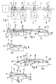
- a system or device is shown as for example to control a machine in the Assembly or manufacturing technology can be used. It there is a central control unit 1, the one Control program contains the operating mode of the individual components of the system is controlled. Preferably it is a programmable logic controller Control system (PLC).
- PLC programmable logic controller Control system
- a fieldbus 2 is connected to the central control unit 1.
- ASI ASI specification.
- It is a 2-wire bus or 2-wire bus, consisting of two wire-shaped conductors 3, 4. It can be individual conductors as is, but also to be integrated in a jointly insulated cable Ladder.
- the control signals are transmitted expediently in serial transmission technology.
- the central control unit 1 transmits the Consumers 5 certain control signals via the fieldbus 2 prompt consumers 5 to take certain actions.
- the central control unit 1 receives the Fieldbus 2 control signals originating from the sensors 6 influence the signal output. In this way lies one integrated control.
- the control device 7 according to the invention is advantageous Way in the transmission of control signals between the fieldbus 2 and at least one consumer and / or sensor used. So it is suitable for Signal transmission in both transmission directions. Preferred designs are shown in FIGS. 2 to 7.
- a valve assembly 8 is shown, the several consecutively alongside each other arranged control valves 12 includes. In the embodiment there are four control valves 12.
- the control valves 12 are on a plate or strip-shaped Fluid distributor 13 attached.
- the fluid distributor 13 is along a plurality of fluid channels 14 pulled through. These flow in a manner known per se certain pattern on the assembly surface of the fluid distributor 13 on which the control valves 12 sit. About one or several of the fluid channels 14 are centralized Pressure medium supply, other of the fluid channels 14 can for Exhaust air guide, and still another of the fluid channels 14 can contain pilot print media.
- the structure can correspond, for example, to that used in DE 42 30 414 Al is described.
- the control valves 12 control the supply and discharge of especially pneumatic pressure medium to any Working units 15, as exemplified in FIGS. 4 and 6 are shown.
- This is, for example fluid actuated linear drives or working cylinders.
- openings 16 are provided at which to leading units of work 15, not in the drawing Pressure fluid lines shown in more detail can be connected.
- a valve spool arranged in the control valves 12 determined by his respective position Flow direction of the pressure medium and thus the operating behavior the connected work unit.
- the respective switching position of the valve spool one respective control valve 12 is by one or more electrically actuated valve drives 17 specified.
- the Control valves. 2 and 3 each have two Valve actuators 17, e.g. in the area of each other opposite end faces of the control valve 12 is attached are.
- the valve drives 17 of the embodiment are Electromagnetic devices in a manner known per se a magnet coil 18 and a movable magnet armature 22 contain. Electrical supplied to the solenoid 18 Control signals influence the position of the armature 22 and thereby the action on the valve slide Pressure medium from the pilot channels 14. According to the selected pressurization results in a certain Switch position of the valve spool.
- valve drives 17 In the exemplary embodiments shown, they are above mentioned consumer 5 formed by the valve drives 17.
- the control device 7 comprises a preferably block-shaped control module 23.
- a bus communication unit is located inside this control module 23 24, the present as an ASI bus station is designed.
- Connection means 25 of a suitable type available, which is a detachable Allow the connection of the conductors 3, 4 of the fieldbus 2.
- the connected conductors 3, 4 are above the first internal ones Conductor 26 in electrical communication with the bus communication unit 24.
- Elsewhere in the field of Outside of the control module 23 is a electrical contact device 27. Via second internal Head 28 also communicates this with the bus communication unit 24th
- the control module 23 is directly on one of the valve drives 17 mounted. A corresponding fastening screw is indicated at 31.
- the electrical contact device 27 is in electrical connection with the associated valve drive 17 provided contact means 32, the internal conductor of the valve drive 17th are connected to its magnetic coil 18.
- bus communication unit 24 is in the electrical connection between the fieldbus 2 and the Consumer 5 interposed.
- the bus communication unit reads during operation of the arrangement 24 the signals sent through the fieldbus 2. As well as an on the relevant bus communication unit 24 addressed Control signal arrives, causes the bus communication unit 24 the corresponding action, for example tightening the armature 22 to move of the valve member.
- the control module 23 not only has the electrical contact device 27 as signal output. It is beyond that further signal outputs 33 are provided on the control module 23.
- the control module 23 according to the example has three such additional signal outputs 33 so that, with inclusion the electrical contact device 27, the control module 23 is equipped with a total of four signal outputs.
- the three additional signal outputs 33 are independent from each other via third internal conductors 34 to the bus communication unit 24 electrically connected. Furthermore stands each of these additional signal outputs 33 with a further consumers 5 ', 5' ', 5' '' in electrical Connection. These are in turn valve actuators 17 ', 17' ', 17' ''.
- Valve drive 17 One valve drive 17 'sits on the same control valve 12, on the uch the first carrying the control module 23 Valve drive 17 is seated.
- the other two valve actuators 17 ′′, 17 ′′ ′′ are in a corresponding manner in the present case on one of the other control valves 12 '. That way the control module 23 simultaneously for the control of several Valve drives 17 as well as several control valves 12 responsible.
- the assigned bus communication unit 24 addressed via the fieldbus 2 from the central control unit 1 coming control signals contain the for the Activation of the connected consumers 5, 5 ', 5' ', 5' '' required information. These are from the bus communication unit 24 evaluated, and accordingly the connected consumers are actuated.
- the sensors 6 are so-called reed sensors, It could just as well be other types of sensors act like inductive, magnetoresistive or magnetostrictive sensors.
- the term "Sensors” include any device that Measure operating parameters.
- the control module 23 is mounted on one of the sensors 6.
- the electrical contact device 27 provided on it with the sensor device inside the sensor 6 in electrical connection.
- a signal input by using it signals originating from the sensor 6 are fed in the connected bus communication unit 24 with a corresponding one Control sent to fieldbus 2 from where they reach the central control unit 1.
- the control module 23 also has three more here Signal inputs 35. Each of these signal inputs 35 is on another sensor 6 ', 6' ', 6' ' connected.
- the one Sensor 6 ' is located on the same work unit 15 like the sensor 6 carrying the control module 23.
- the two other connected sensors 6 '', 6 '' ' are on at least one further working unit 15 '. So go in the bus communication unit 24, the control signals several independent sensors then via the fieldbus 2 of the central control unit 1 fed.
- Fig. 4 shows a mixing arrangement in which on the Control module 23 both signal inputs and signal outputs available.
- the control module 23 sits on a Consumer 5, so that associated with this Contact device 27 acts as a signal output.
- Over one another signal output 33 is a second consumer 5 'in Shape of another valve drive 17 'connected.
- control module 23 with a mixed arrangement of signal inputs and signal outputs to be placed directly on a sensor and from there another sensor and other consumers head for.
- flexible electrical conductor 36 In the embodiment are cables with one or more each internal wires surrounded by an insulation jacket are. Cables of this type are very inexpensive and easy by the user to the desired length cut to size.
- the electrical conductor 36 is preferably one each Connection part 37 attached. This connector 37 will detachable on the consumer 5 or sensor 6 concerned appropriate.
- a contact device 38 arranged on it is attached to a consumer 5 or sensor 6 Condition with the contact means 32 provided on it electrical connection, which in turn is connected to the internal Setup of the assigned consumer or sensor are connected.
- FIGS. 2 to 4 and 6 can be shown Assemble control devices 7 very easily as required and disassemble. Except for the connection of the fieldbus 2 is only attaching the control module 23 and the three Connection parts 37 required.
- Control module 23 and the connecting parts 37 preferably designed as plug parts. So the start is a Mating process.
- the electrical contact device 27, the electrical contact arrangement 38 and the contact means 32 are designed as plug contacts that lead to multiple plug devices or multi-pin plug connections can be summarized.
- connection parts 37 an additional fixation to which they load-bearing element 5, 6 by means of fastening screws 31.
- Fig. 5 shows a design that a releasable coupling of the relevant ladder 36 enables.
- the two additional signal inputs 35 present here are each provided with a coupling device 42. At this is preferably a plug-in coupling device.
- the electrical not shown Heads 36 can thus quickly in a need Operation can be connected or removed.
- control valve 12 is a monostable Valve, so that a valve actuator 17 for actuation is sufficient.
- the control module 23 sits on this two signal inputs 35 shown unassigned can Electrical conductors coming from sensors can be detached be connected.
- FIG. 7 shows a design in which the control module 23 and a connecting part 37 are rigidly connected to one another.
- the rigid connection is made via e.g. web-like Bridge element 43, which with the housings of Connection part 37 and the control module 23 in one piece can be trained.
- the between the connector 37 and the electrical module 36 extending to the control module 23 extend inside the bridging member 43 and are well protected. Because no flexibility is required , they can be in the form of conductor tracks on one or Several circuit boards can be provided inside the itself from the control module 23, the bridging element 43 and the connecting part 37 composing unit 44 added are.
- This assembly 44 thus forms a total practically a multiple plug device, which is in one single assembly process to the assigned consumers 5th or sensors 6 can be applied. Such arrangements are recommended for special solutions with large quantities, that do not require any connection variation.
- the control device 7 can be in the Operate in conjunction with all actuators operated by electromagnetic Elements can be controlled. It is suitable for consumers 5 and sensors 6 of different types and Size, without further ado to one and the same control device 7 different consumer or sensor types can be connected.
- Control modules 23 can be varied at different points connected to it along the fieldbus.
- Cross branches to the not directly to the Control modules 23 arranged consumers 5 or sensors 6 can be via the electrical conductor 36 and the Perform connection parts 37, the latter being simplest Can be of type and in particular no separate bus communication unit need.
- the electrical conductors 36 designed as cables can be designed as a spiral cable to be easy to use to be able to make a variable length adjustment.
Landscapes
- Engineering & Computer Science (AREA)
- Physics & Mathematics (AREA)
- Fluid Mechanics (AREA)
- Mechanical Engineering (AREA)
- General Engineering & Computer Science (AREA)
- Power Engineering (AREA)
- Arrangements For Transmission Of Measured Signals (AREA)
- Magnetically Actuated Valves (AREA)
- Small-Scale Networks (AREA)
- Selective Calling Equipment (AREA)
- Servomotors (AREA)
- Indication Of The Valve Opening Or Closing Status (AREA)
- Lubrication Of Internal Combustion Engines (AREA)
- Valve Device For Special Equipments (AREA)
- Control By Computers (AREA)
Claims (16)
- Dispositif de commande destiné à être utilisé lors de la transmission de signaux de commande entre un bus de champ (2) et au moins un récepteur (5) et/ou capteur (6), en particulier pour la commande de soupapes (12), comportant un module de commande (23) qui présente une unité de communication par bus (24) ainsi que des moyens de branchement (25), servant à son branchement à un bus de champ (2), et qui peut être relié avec au moins un récepteur (5) et/ou capteur (6) de manière que l'unité de communication par bus (24) soit accouplée électriquement avec le récepteur (5) et/ou le capteur (6), par un dispositif de contact (27) prévu sur le module de commande (23), et comportant au moins une sortie de signaux (33) supplémentaire, reliée à l'unité de communication par bus (24) du module de commande (23), en vue de l'accouplement d'au moins un récepteur (5', 5'', 5''') supplémentaire, caractérisé en ce que le module de commande (23) est conçu de manière à être monté directement sur le ou les récepteur(s) (5) et/ou capteur(s) (6), pour le raccordement de son dispositif de contact (27), et en ce que la ou les sortie(s) de signaux (33) supplémentaire(s) est (sont) prévue(s) sur le module de commande (23) en supplément au dispositif de contact (27) et aux moyens de branchement (25) pour le bus de champ (2).
- Dispositif de commande selon la revendication 1, caractérisé en ce que sur le module de commande (23) est prévue en supplément au moins une entrée de signaux (35), pour l'accouplement d'au moins un capteur (6', 6'', 6''').
- Dispositif de commande selon la revendication 1 ou 2, caractérisé en ce que le module de commande (23) est un élément formant connecteur.
- Dispositif de commande selon l'une des revendications 1 à 3, caractérisé en ce qu'au moins une entrée de signaux (35) et/ou une sortie de signaux (33) est reliée, par des conducteurs électriques (36), avec une partie de branchement (47) disposée à l'extérieur du module de commande (23), qui peut être raccordée à un autre récepteur (5', 5'', 5''') et/ou capteur (6', 6'', 6'''), afin d'accoupler électriquement celui-ci à l'unité de communication par bus (24).
- Dispositif de commande selon la revendication 4, caractérisé en ce que toutes les sorties de signaux et/ou entrées de signaux (35), se trouvant sur le module de commande (23), sont reliées chacune à une partie de branchement (37) externe.
- Dispositif de commande selon la revendication 4 ou 5, caractérisé en ce que les conducteurs électriques (36), menant à une partie de branchement (37) respective, sont réalisés en tant que conducteurs flexibles, en particulier sous la forme de câbles.
- Dispositif de commande selon l'une des revendications 4 à 6, caractérisé en ce qu'au moins une partie de branchement (37) est reliée rigidement au module de commande (23).
- Dispositif de commande selon l'une des revendications 4 à 7, caractérisé en ce que la partie de branchement (37) est un élément à connecteur.
- Dispositif de commande selon l'une des revendications 1 à 8, caractérisé en ce que sur au moins une entrée de signaux (35) et/ou sortie de signaux (33), il est prévu en dispositif de couplage (42) pour l'accouplement séparable des conducteurs électriques (36), menant à un récepteur (5', 5'', 5''') et/ou capteur (6', 6'', 6''').
- Dispositif de commande selon la revendication 9, caractérisé en ce que le dispositif de couplage (42) est un dispositif de couplage à enfichage.
- Dispositif de commande selon l'une des revendications 1 à 10, caractérisé en ce que l'unité de communication par bus (24) est un poste de bus ASI pour un bus ASI.
- Dispositif de commande selon l'une des revendications 1 à 11, caractérisé en ce qu'au moins un récepteur (5) est constitué par un dispositif d'actionnement de soupape (17), actionné électriquement, par exemple un dispositif électromagnétique.
- Dispositif de commande selon la revendication 12, caractérisé en ce que plusieurs soupapes de commande (12), pourvues chacune d'au moins un dispositif d'actionnement de soupape (17), sont réunies en un ou plusieurs ensembles (8).
- Dispositif de commande selon l'une des revendications 1 à 13, caractérisé en ce qu'au moins un capteur (6, 6') est associé à un dispositif d'entraínement linéaire (15, 15'), par exemple à un vérin actionné au moyen d'un fluide.
- Dispositif de commande selon l'une des revendications 1 à 14, caractérisé en ce que le module de commande (23) dispose, en supplément au dispositif de contact (27), d'au moins une entrée de signaux (35) et une sortie de signaux (33).
- Dispositif de commande selon l'une des revendications 1 à 15, caractérisé en ce que sont prévus plusieurs modules de commande (23), qui peuvent être raccordés de manière variable au bus de champ (2), en différents points, le long de celui-ci.
Applications Claiming Priority (3)
| Application Number | Priority Date | Filing Date | Title |
|---|---|---|---|
| DE4444024A DE4444024A1 (de) | 1994-12-10 | 1994-12-10 | Steuereinrichtung, insbesondere zur Ansteuerung von Ventilen |
| DE4444024 | 1994-12-10 | ||
| PCT/EP1995/003854 WO1996019027A1 (fr) | 1994-12-10 | 1995-09-29 | Dispositif de commande, notamment de commande de soupapes |
Publications (2)
| Publication Number | Publication Date |
|---|---|
| EP0796519A1 EP0796519A1 (fr) | 1997-09-24 |
| EP0796519B1 true EP0796519B1 (fr) | 1998-06-10 |
Family
ID=6535468
Family Applications (1)
| Application Number | Title | Priority Date | Filing Date |
|---|---|---|---|
| EP95934117A Expired - Lifetime EP0796519B1 (fr) | 1994-12-10 | 1995-09-29 | Dispositif de commande, notamment de commande de soupapes |
Country Status (8)
| Country | Link |
|---|---|
| US (1) | US5929536A (fr) |
| EP (1) | EP0796519B1 (fr) |
| JP (1) | JP3035353B2 (fr) |
| KR (1) | KR100282075B1 (fr) |
| AT (1) | ATE167339T1 (fr) |
| DE (2) | DE4444024A1 (fr) |
| ES (1) | ES2116771T3 (fr) |
| WO (1) | WO1996019027A1 (fr) |
Cited By (1)
| Publication number | Priority date | Publication date | Assignee | Title |
|---|---|---|---|---|
| EP2354563A1 (fr) | 2010-02-08 | 2011-08-10 | FESTO AG & Co. KG | Agencement de vannes |
Families Citing this family (19)
| Publication number | Priority date | Publication date | Assignee | Title |
|---|---|---|---|---|
| DE19653714C1 (de) * | 1996-12-10 | 1997-12-11 | Mannesmann Ag | Einrichtung zur Übermittlung von Steuersignalen an Ventile |
| DE59709919D1 (de) * | 1997-09-18 | 2003-05-28 | Endress & Hauser Gmbh & Co Kg | Messgerät-Bussystem-Anordnung und Adapter dafür |
| DE19750736A1 (de) * | 1997-11-15 | 1999-05-20 | Volkswagen Ag | Steuerungssystem und -verfahren für mehrere durch den Fahrer aktivierbare Module in einem Fahrzeug |
| DE29810102U1 (de) | 1998-06-05 | 1998-08-20 | Festo AG & Co, 73734 Esslingen | Steuereinrichtung für fluidbetätigte Verbraucher |
| DE19827883A1 (de) * | 1998-06-23 | 2000-01-05 | Lorch Ges & Co Gmbh J | Baueinheit für eine Druckluftanlage |
| DE19853739A1 (de) * | 1998-11-21 | 2000-05-25 | Mannesmann Rexroth Ag | Verfahren zur Ansteuerung von elektrisch betätigten Schaltventilen |
| JP3590772B2 (ja) * | 2001-01-16 | 2004-11-17 | Smc株式会社 | センサ付き電磁弁 |
| US7735395B2 (en) * | 2004-07-20 | 2010-06-15 | Gm Global Technology Operations, Inc. | External speed sensor and method |
| DE102006030039B4 (de) * | 2006-06-29 | 2009-06-18 | Festo Ag & Co. Kg | Ventileinrichtung |
| DE102006056089A1 (de) | 2006-11-28 | 2008-05-29 | Festo Ag & Co. | Ventileinrichtung |
| DE102009016604B3 (de) * | 2009-04-08 | 2010-07-01 | Festo Ag & Co. Kg | Ventilanordnung |
| DE102011080878A1 (de) | 2011-06-21 | 2012-12-27 | Ifm Electronic Gmbh | Steuergerät für ein pneumatisches Ventil |
| AU2013239338B2 (en) * | 2012-03-27 | 2016-12-08 | Brt Group Pty Ltd | Solenoid device with sensor |
| PL2693280T3 (pl) * | 2012-08-01 | 2018-06-29 | Joseph Vögele AG | Maszyna do budowy dróg z systemem pomiarowym i sposób pomiaru |
| US10006557B2 (en) | 2013-03-15 | 2018-06-26 | Asco, L.P. | Valve manifold circuit board with serial communication and control circuit line |
| JP6467711B2 (ja) * | 2015-06-24 | 2019-02-13 | Smc株式会社 | 多連一体型マニホールドバルブ |
| GB201613901D0 (en) * | 2016-08-12 | 2016-09-28 | Artemis Intelligent Power Ltd | Valve for fluid working machine, fluid working machine and method of operation |
| JP7632993B2 (ja) * | 2019-09-18 | 2025-02-19 | ナブテスコ株式会社 | 電磁比例弁、建設機械 |
| DE102023107648A1 (de) * | 2023-03-27 | 2024-10-02 | Festo Se & Co. Kg | Ventilanordnung und Verfahren zur Installation einer Ventilanordnung |
Family Cites Families (13)
| Publication number | Priority date | Publication date | Assignee | Title |
|---|---|---|---|---|
| US4245319A (en) * | 1979-03-19 | 1981-01-13 | Cyborex Laboratories, Inc. | Energy management method and apparatus utilizing duty cycle reduction synchronized with the zero points of the applied voltage |
| GB2083301B (en) * | 1980-09-01 | 1984-09-26 | South Eastern Elec Board | Method of and apparatus for controlling loads on an electrical power supply |
| US4694192A (en) * | 1984-11-23 | 1987-09-15 | Honeywell Inc. | Simplified demand limit control |
| FR2624627B1 (fr) * | 1987-12-15 | 1990-06-15 | Legrand Sa | Pilote programmable de gestion d'energie electrique |
| US5191520A (en) * | 1989-02-06 | 1993-03-02 | Boral Johns Perry Industries Pty. Ltd. | Power supply system |
| CH683021A5 (de) * | 1991-06-25 | 1993-12-31 | Walter Ag | Anordnung mit mehreren Magnetventilen, insbesondere für eine Ventilbatterie. |
| US5384490A (en) * | 1992-06-15 | 1995-01-24 | Unisys Corporation | Universal power distribution system |
| DE9214301U1 (de) * | 1992-09-11 | 1992-12-24 | Festo AG & Co, 73734 Esslingen | Elektro-pneumatische Steuereinrichtung |
| DE4230414C2 (de) | 1992-09-11 | 1996-02-01 | Festo Kg | Elektro-pneumatische Steuereinrichtung |
| US5345225A (en) * | 1992-10-30 | 1994-09-06 | Scientific-Atlanta, Inc. | Tamper detection system for load management device |
| DE59401089D1 (de) * | 1993-04-20 | 1997-01-02 | Siemens Ag | Elektrischer anschlussblock mit modularem aufbau |
| DE4312729A1 (de) * | 1993-04-20 | 1994-10-27 | Festo Kg | Ventilstation |
| US5586271A (en) * | 1994-09-27 | 1996-12-17 | Macrolink Inc. | In-line SCSI bus circuit for providing isolation and bi-directional communication between two portions of a SCSI bus |
-
1994
- 1994-12-10 DE DE4444024A patent/DE4444024A1/de not_active Withdrawn
-
1995
- 1995-09-29 DE DE59502543T patent/DE59502543D1/de not_active Expired - Lifetime
- 1995-09-29 JP JP08518105A patent/JP3035353B2/ja not_active Expired - Lifetime
- 1995-09-29 KR KR1019970703887A patent/KR100282075B1/ko not_active Expired - Fee Related
- 1995-09-29 ES ES95934117T patent/ES2116771T3/es not_active Expired - Lifetime
- 1995-09-29 WO PCT/EP1995/003854 patent/WO1996019027A1/fr not_active Ceased
- 1995-09-29 US US08/849,271 patent/US5929536A/en not_active Expired - Fee Related
- 1995-09-29 AT AT95934117T patent/ATE167339T1/de not_active IP Right Cessation
- 1995-09-29 EP EP95934117A patent/EP0796519B1/fr not_active Expired - Lifetime
Cited By (1)
| Publication number | Priority date | Publication date | Assignee | Title |
|---|---|---|---|---|
| EP2354563A1 (fr) | 2010-02-08 | 2011-08-10 | FESTO AG & Co. KG | Agencement de vannes |
Also Published As
| Publication number | Publication date |
|---|---|
| DE59502543D1 (de) | 1998-07-16 |
| JP3035353B2 (ja) | 2000-04-24 |
| KR987000718A (ko) | 1998-03-30 |
| JPH10504092A (ja) | 1998-04-14 |
| ES2116771T3 (es) | 1998-07-16 |
| KR100282075B1 (ko) | 2001-03-02 |
| ATE167339T1 (de) | 1998-06-15 |
| US5929536A (en) | 1999-07-27 |
| WO1996019027A1 (fr) | 1996-06-20 |
| EP0796519A1 (fr) | 1997-09-24 |
| DE4444024A1 (de) | 1996-06-13 |
Similar Documents
| Publication | Publication Date | Title |
|---|---|---|
| DE4444024A1 (de) | Steuereinrichtung, insbesondere zur Ansteuerung von Ventilen | |
| EP0442033B1 (fr) | Unité de montage de valve | |
| DE60016655T3 (de) | Magnetventilverteilplatte, angetrieben durch seriellen Signale | |
| DE4230414C2 (de) | Elektro-pneumatische Steuereinrichtung | |
| DE10049958B4 (de) | Fluidtechnische Anordnung sowie Ventilanordnung und Aktuator hierfür | |
| EP1013940B1 (fr) | Arrangement de soupape | |
| EP0803653B1 (fr) | Système pneumatique de commande | |
| EP1710447B1 (fr) | Appareil de commande électro-fluidique | |
| EP0962663B1 (fr) | Dispositif de commande pour récepteurs actionnés par fluide | |
| EP1041325B1 (fr) | Assemblage de soupapes | |
| DE9310438U1 (de) | Ventilstation | |
| DE9211109U1 (de) | Elektro-pneumatische Steuereinrichtung | |
| EP0713980B1 (fr) | Dispositif d'entraínement | |
| EP0629783B1 (fr) | ContrÔle combiné de valves pneumatiques et hydrauliques | |
| EP0621407B1 (fr) | Ensemble valve | |
| DE10203792B4 (de) | Pneumatische Ventileinheit mit einer parallelen elektrischen Verdrahtung | |
| EP0930130B1 (fr) | Dispositif de serrage | |
| DE102010031922B4 (de) | Ventileinheit | |
| EP1284371B1 (fr) | Assemblage de valves sous forme de matrice | |
| DE9214301U1 (de) | Elektro-pneumatische Steuereinrichtung | |
| EP2131044B1 (fr) | Dispositif de liaison électrique de plusieurs soupapes électropneumatiques agencées en tant qu'unités de soupape | |
| DE10162525C1 (de) | Elektromagnetisches Mehrwegeventil mit einer kontaktlosen Übertragung von Ansteuerungssignalen | |
| EP0624831A2 (fr) | Dispositif de commande pour l'utilisation en coopération avec des systèmes actionnés par des fluides | |
| DE102005057786B4 (de) | Elektro-fluidische Steuereinrichtung mit mindestens einer Ventilbatterie | |
| AT405464B (de) | Pneumatische betätigungsanordnung |
Legal Events
| Date | Code | Title | Description |
|---|---|---|---|
| PUAI | Public reference made under article 153(3) epc to a published international application that has entered the european phase |
Free format text: ORIGINAL CODE: 0009012 |
|
| 17P | Request for examination filed |
Effective date: 19970510 |
|
| AK | Designated contracting states |
Kind code of ref document: A1 Designated state(s): AT CH DE ES FR GB GR IT LI NL SE |
|
| GRAG | Despatch of communication of intention to grant |
Free format text: ORIGINAL CODE: EPIDOS AGRA |
|
| 17Q | First examination report despatched |
Effective date: 19971002 |
|
| RAP1 | Party data changed (applicant data changed or rights of an application transferred) |
Owner name: FESTO AG & CO |
|
| GRAG | Despatch of communication of intention to grant |
Free format text: ORIGINAL CODE: EPIDOS AGRA |
|
| GRAH | Despatch of communication of intention to grant a patent |
Free format text: ORIGINAL CODE: EPIDOS IGRA |
|
| GRAH | Despatch of communication of intention to grant a patent |
Free format text: ORIGINAL CODE: EPIDOS IGRA |
|
| GRAA | (expected) grant |
Free format text: ORIGINAL CODE: 0009210 |
|
| AK | Designated contracting states |
Kind code of ref document: B1 Designated state(s): AT CH DE ES FR GB GR IT LI NL SE |
|
| PG25 | Lapsed in a contracting state [announced via postgrant information from national office to epo] |
Ref country code: GR Free format text: LAPSE BECAUSE OF FAILURE TO SUBMIT A TRANSLATION OF THE DESCRIPTION OR TO PAY THE FEE WITHIN THE PRESCRIBED TIME-LIMIT Effective date: 19980610 |
|
| REF | Corresponds to: |
Ref document number: 167339 Country of ref document: AT Date of ref document: 19980615 Kind code of ref document: T |
|
| ITF | It: translation for a ep patent filed | ||
| REG | Reference to a national code |
Ref country code: CH Ref legal event code: EP |
|
| GBT | Gb: translation of ep patent filed (gb section 77(6)(a)/1977) |
Effective date: 19980611 |
|
| REF | Corresponds to: |
Ref document number: 59502543 Country of ref document: DE Date of ref document: 19980716 |
|
| REG | Reference to a national code |
Ref country code: ES Ref legal event code: FG2A Ref document number: 2116771 Country of ref document: ES Kind code of ref document: T3 |
|
| PG25 | Lapsed in a contracting state [announced via postgrant information from national office to epo] |
Ref country code: AT Free format text: LAPSE BECAUSE OF NON-PAYMENT OF DUE FEES Effective date: 19980929 |
|
| ET | Fr: translation filed | ||
| PLBE | No opposition filed within time limit |
Free format text: ORIGINAL CODE: 0009261 |
|
| STAA | Information on the status of an ep patent application or granted ep patent |
Free format text: STATUS: NO OPPOSITION FILED WITHIN TIME LIMIT |
|
| 26N | No opposition filed | ||
| PG25 | Lapsed in a contracting state [announced via postgrant information from national office to epo] |
Ref country code: LI Free format text: LAPSE BECAUSE OF NON-PAYMENT OF DUE FEES Effective date: 19990930 Ref country code: CH Free format text: LAPSE BECAUSE OF NON-PAYMENT OF DUE FEES Effective date: 19990930 |
|
| REG | Reference to a national code |
Ref country code: CH Ref legal event code: PL |
|
| REG | Reference to a national code |
Ref country code: GB Ref legal event code: IF02 |
|
| PGFP | Annual fee paid to national office [announced via postgrant information from national office to epo] |
Ref country code: ES Payment date: 20030904 Year of fee payment: 9 |
|
| PG25 | Lapsed in a contracting state [announced via postgrant information from national office to epo] |
Ref country code: ES Free format text: LAPSE BECAUSE OF NON-PAYMENT OF DUE FEES Effective date: 20040930 |
|
| REG | Reference to a national code |
Ref country code: ES Ref legal event code: FD2A Effective date: 20040930 |
|
| PGFP | Annual fee paid to national office [announced via postgrant information from national office to epo] |
Ref country code: SE Payment date: 20070917 Year of fee payment: 13 Ref country code: NL Payment date: 20070919 Year of fee payment: 13 |
|
| PGFP | Annual fee paid to national office [announced via postgrant information from national office to epo] |
Ref country code: IT Payment date: 20080910 Year of fee payment: 14 Ref country code: FR Payment date: 20080917 Year of fee payment: 14 |
|
| PGFP | Annual fee paid to national office [announced via postgrant information from national office to epo] |
Ref country code: GB Payment date: 20080911 Year of fee payment: 14 |
|
| PG25 | Lapsed in a contracting state [announced via postgrant information from national office to epo] |
Ref country code: NL Free format text: LAPSE BECAUSE OF NON-PAYMENT OF DUE FEES Effective date: 20090401 |
|
| NLV4 | Nl: lapsed or anulled due to non-payment of the annual fee |
Effective date: 20090401 |
|
| GBPC | Gb: european patent ceased through non-payment of renewal fee |
Effective date: 20090929 |
|
| REG | Reference to a national code |
Ref country code: FR Ref legal event code: ST Effective date: 20100531 |
|
| PG25 | Lapsed in a contracting state [announced via postgrant information from national office to epo] |
Ref country code: SE Free format text: LAPSE BECAUSE OF NON-PAYMENT OF DUE FEES Effective date: 20080930 Ref country code: FR Free format text: LAPSE BECAUSE OF NON-PAYMENT OF DUE FEES Effective date: 20090930 |
|
| PG25 | Lapsed in a contracting state [announced via postgrant information from national office to epo] |
Ref country code: GB Free format text: LAPSE BECAUSE OF NON-PAYMENT OF DUE FEES Effective date: 20090929 |
|
| PG25 | Lapsed in a contracting state [announced via postgrant information from national office to epo] |
Ref country code: IT Free format text: LAPSE BECAUSE OF NON-PAYMENT OF DUE FEES Effective date: 20090929 |
|
| PGFP | Annual fee paid to national office [announced via postgrant information from national office to epo] |
Ref country code: DE Payment date: 20120725 Year of fee payment: 18 |
|
| REG | Reference to a national code |
Ref country code: DE Ref legal event code: R119 Ref document number: 59502543 Country of ref document: DE Effective date: 20140401 |
|
| PG25 | Lapsed in a contracting state [announced via postgrant information from national office to epo] |
Ref country code: DE Free format text: LAPSE BECAUSE OF NON-PAYMENT OF DUE FEES Effective date: 20140401 |