EP0796549B1 - Appareil d'examen par rayons x comprenant un systeme de commande de l'exposition - Google Patents
Appareil d'examen par rayons x comprenant un systeme de commande de l'exposition Download PDFInfo
- Publication number
- EP0796549B1 EP0796549B1 EP96930335A EP96930335A EP0796549B1 EP 0796549 B1 EP0796549 B1 EP 0796549B1 EP 96930335 A EP96930335 A EP 96930335A EP 96930335 A EP96930335 A EP 96930335A EP 0796549 B1 EP0796549 B1 EP 0796549B1
- Authority
- EP
- European Patent Office
- Prior art keywords
- image
- signal
- section
- ray
- examination apparatus
- Prior art date
- Legal status (The legal status is an assumption and is not a legal conclusion. Google has not performed a legal analysis and makes no representation as to the accuracy of the status listed.)
- Expired - Lifetime
Links
- 230000003287 optical effect Effects 0.000 claims abstract description 52
- 238000003384 imaging method Methods 0.000 claims description 2
- 230000035945 sensitivity Effects 0.000 abstract description 8
- 230000010354 integration Effects 0.000 description 8
- OAICVXFJPJFONN-UHFFFAOYSA-N Phosphorus Chemical compound [P] OAICVXFJPJFONN-UHFFFAOYSA-N 0.000 description 4
- 239000002800 charge carrier Substances 0.000 description 4
- 238000010276 construction Methods 0.000 description 3
- 230000006978 adaptation Effects 0.000 description 2
- 230000004888 barrier function Effects 0.000 description 2
- 238000010894 electron beam technology Methods 0.000 description 2
- 230000005855 radiation Effects 0.000 description 2
- 238000010521 absorption reaction Methods 0.000 description 1
- XAGFODPZIPBFFR-UHFFFAOYSA-N aluminium Chemical compound [Al] XAGFODPZIPBFFR-UHFFFAOYSA-N 0.000 description 1
- 229910052782 aluminium Inorganic materials 0.000 description 1
- 239000004411 aluminium Substances 0.000 description 1
- 230000003321 amplification Effects 0.000 description 1
- 230000015572 biosynthetic process Effects 0.000 description 1
- 230000008878 coupling Effects 0.000 description 1
- 238000010168 coupling process Methods 0.000 description 1
- 238000005859 coupling reaction Methods 0.000 description 1
- 230000001678 irradiating effect Effects 0.000 description 1
- 239000000463 material Substances 0.000 description 1
- 238000003199 nucleic acid amplification method Methods 0.000 description 1
- 239000013307 optical fiber Substances 0.000 description 1
- 239000004065 semiconductor Substances 0.000 description 1
Images


Classifications
-
- H—ELECTRICITY
- H05—ELECTRIC TECHNIQUES NOT OTHERWISE PROVIDED FOR
- H05G—X-RAY TECHNIQUE
- H05G1/00—X-ray apparatus involving X-ray tubes; Circuits therefor
- H05G1/08—Electrical details
- H05G1/60—Circuit arrangements for obtaining a series of X-ray photographs or for X-ray cinematography
-
- H—ELECTRICITY
- H05—ELECTRIC TECHNIQUES NOT OTHERWISE PROVIDED FOR
- H05G—X-RAY TECHNIQUE
- H05G1/00—X-ray apparatus involving X-ray tubes; Circuits therefor
- H05G1/08—Electrical details
- H05G1/26—Measuring, controlling or protecting
- H05G1/30—Controlling
- H05G1/36—Temperature of anode; Brightness of image power
-
- H—ELECTRICITY
- H05—ELECTRIC TECHNIQUES NOT OTHERWISE PROVIDED FOR
- H05G—X-RAY TECHNIQUE
- H05G1/00—X-ray apparatus involving X-ray tubes; Circuits therefor
- H05G1/08—Electrical details
- H05G1/26—Measuring, controlling or protecting
- H05G1/30—Controlling
- H05G1/38—Exposure time
- H05G1/42—Exposure time using arrangements for switching when a predetermined dose of radiation has been applied, e.g. in which the switching instant is determined by measuring the electrical energy supplied to the tube
- H05G1/44—Exposure time using arrangements for switching when a predetermined dose of radiation has been applied, e.g. in which the switching instant is determined by measuring the electrical energy supplied to the tube in which the switching instant is determined by measuring the amount of radiation directly
Definitions
- the invention relates to an X-ray examination apparatus, comprising an X-ray detector for converting an X-ray image into an optical image and an exposure- control system comprising a photodetector for measuring brightness values of the optical image, which photodetector comprises an image pick-up section.
- An X-ray examination apparatus of this kind is known from European Patent Application EP 0 629 105.
- the known X-ray examination apparatus comprises an exposure-control system in which the photodetector is a CCD sensor and in which a photodiode is used as the photosensor.
- the exposure-control system comprises an adjusting unit for deriving a voltage-frequency (V/f) signal from the photosensor signal.
- the signal level of the photosensor signal governs the frequency of the voltage-frequency signal. Since the photosensor signal represents the mean brightness in the optical image, the frequency of the V/f signal represents the mean brightness of the optical image.
- the V/f signal is applied to a clock unit which adjusts the integration time of the photodetector on the basis of the frequency of the V/f signal.
- the adjusting unit thus adjusts the sensitivity of the CCD sensor on the basis of the mean brightness in the optical image.
- the brightness of the optical image is controlled on the basis of the photodetector signal which contains image information of a region of interest (ROI) in the optical image, for example by adjustment of the X-ray source, or the signal level of the electronic image signal is controlled by adjustment of the gain of the image pick-up apparatus or of the aperture of a diaphragm of the image pick-up apparatus.
- ROI region of interest
- the frequency of the V/f signal is higher, thus reducing the integration time of the photodetector. If the integration time becomes shorter than the time required for reading out the CCD sensor, the integration of an image by the photodetector of the exposure-control system is stopped if the preceding image has not yet been read from the image memory of the CCD sensor. It is a drawback of the known X-ray examination apparatus that in that case the image just integrated cannot be transferred to the image memory; it is then necessary to pick up an image again which, after the image memory has been vacated, is transferred to the image memory and subsequently read out.
- the known X-ray apparatus requires a comparatively long period of time, i.e. almost twice the read-out time, for adapting the control signal to a change in the optical image, for example a brightness increase.
- an X-ray examination apparatus in accordance with the invention which is characterized in that the image storage section includes in a first storage section and a second storage section and is arranged to receive brightness values in the first storage section while brightness values are being read from the second storage section.
- the X-ray examination apparatus includes an image pick-up apparatus for deriving an image signal from the optical image.
- the image signal is, for example an electronic video signal whose signal levels represent brightness values of the optical image.
- the exposure control system ensures that the X-ray apparatus is adjusted so that an X-ray image of high diagnostic quality is formed and reproduced, i.e. that small details are included in the X-ray image and reproduced in a suitably visible manner. To this end, the exposure control system ensures that the signal level of the image signal is situated in a suitable interval.
- the exposure control system derives a control signal from the photodetector signal. This control signal is used to control the intensity and/or the energy of the X-ray beam.
- the control signal is also suitable for controlling the signal level of the image signal directly or indirectly.
- the image pick-up section includes a plurality of photosensitive elements and the image storage section includes a plurality of image storage elements.
- Individual photosensitive elements convert incident light into electrical charges which represent brightness values of the optical image.
- the optical image is picked up by the image pick-up section during successive, brief time intervals so that successive brightness values of successive images are picked up.
- the electrical charges are stored in the image storage elements.
- the sensitivity of the photodetector is controlled on the basis of the mean brightness of the optical image.
- a photosensor is used to derive a photosensor signal from the optical image. This photosensor signal represents the mean brightness of the optical image and the sensitivity of the photodetector is controlled by means of the photosensor signal.
- the photodetector signal is formed by reading the brightness values of the first image from the first storage section. If the sensitivity of the photodetector has been adjusted to a low value, the image pick-up section will require a very short period of time for picking up an image. As the period of time required for picking up an image is shorter, it will be more likely that the picking up of a next image in the image pick-up section will have been completed before completion of the reading out of the first image. In that situation the next image is stored as a second image in the second storage section. It is thus achieved that the photodetector signal corresponding to the next image becomes available without it being necessary to pick up an image again after the preceding electronic image has been read.
- the X-ray examination apparatus in accordance with the invention thus enables reading of images from the photosensor in rapid succession and adaptation of the control signal on the basis of these images.
- a preferred embodiment of an X-ray examination apparatus in accordance with the invention is characterized in that the first storage section constitutes an image memory, and that the second storage section is constructed as an intermediate memory which is coupled to the image pick-up section and to the image memory.
- the intermediate memory is a storage section which is situated between the image pick-up section and the remainder of the image memory.
- the electronic image is transferred from the image pick-up section to the intermediate memory and, as soon as the image memory has been vacated, the electronic image is transferred from the intermediate memory to the image memory. Transferring an electronic image from the image pick-up section to the intermediate memory and from the intermediate memory to the image memory requires far less time than the reading out of the photodetector signal.
- the electronic image in the intermediate memory can be quickly transferred to the image memory, so that the intermediate memory becomes quickly available again to receive a new electronic image from the image pick-up section. Consequently, within a very short period of time (in comparison with the read-out time) after an electronic image has been read out, the reading out may commence of the next electronic image which has meanwhile been transferred to the vacated image memory.
- a further preferred embodiment of an X-ray examination apparatus in accordance with the invention is characterized in that the image pick-up section is charge-coupled to the intermediate memory and/or that the image pick-up section is charge-coupled to the intermediate memory.
- a further preferred embodiment of an X-ray examination apparatus in accordance with the invention is characterized in that the intermediate memory forms part of the image pick-up section.
- the electronic image in the image pick-up section it suffices to transport the electronic image in the image pick-up section by charge-coupled transfer within the image pick-up section, so that a particularly short period of time is required for storing the electronic image in the intermediate memory.
- the electronic image is sufficiently smaller than the capacity of the image pick-up section, i.e. smaller than the largest image that can be accommodated in its entirety in the image pick-up section, no image information need be lost when a part of the image pick-up section is used as an intermediate memory.
- a further preferred embodiment of an X-ray examination apparatus in accordance with the invention is characterized in that the exposure-control system includes an optical system for imaging at least a part of the optical image on no more than a part of the image pick-up section.
- the optical system ensures that only a part of the image pick-up section is exposed.
- the part of the image pick-up section which is not exposed remains available as an intermediate memory. It is to be noted that from Japanese Patent Application JP 63-48 974 it is known per se to expose only a part of the image pick-up section.
- a further embodiment of an X-ray examination apparatus in accordance with the invention is characterized in that the optical system comprises a gradient index (GRIN) lens.
- GRIN gradient index
- a gradient index (GRIN) lens is a rod-shaped lens having a radially varying refractive index.
- a GRIN lens has a length of approximately one half centimetre and a diameter of from approximately 1 to 2 mm. Because a GRIN lens is so small, it occupies very little space. As a result, the use of such a GRIN lens contributes to compactness of the construction of the exposure-control system. Furthermore, a GRIN lens of suitable length has a particularly short focal distance of approximately 1 mm and a high numerical aperture.
- the GRIN lens can be arranged very near to the photosensitive surface of the photodetector and nevertheless sharply image the optical image on a part of the image pick-up section, the remainder of the image pick-up section not being exposed. This counteracts the disturbing of an electronic image stored in the intermediate image during exposure of the image pick-up section.
- the use of the GRIN lens allows for a compact construction of the exposure-control system. It is to be noted, however, that from Japanese Patent Application JP 4-188 872 it is known per se to expose a single photosensitive element of the image pick-up section by means of an optical fibre.
- a further preferred embodiment of an X-ray examination apparatus in accordance with the invention is characterized in that the exposure-control system is arranged to apply the control signal to the X-ray source or to the high-voltage power supply of the X-ray source.
- the control signal is used to adjust the energy and the intensity of the X-rays on the basis of brightness values in the optical image. This avoids overexposure or underexposure of regions of interest in the optical image.
- the electronic image signal derived from said optical image is used to display the image information with a high diagnostic quality, i.e. in such a manner that small details are suitably visible.
- a further preferred embodiment of an X-ray examination apparatus in accordance with the invention is characterized in that the exposure-control system is arranged to apply the control signal to a control unit or to a diaphragm of the image pick-up apparatus.
- the image pick-up apparatus supplies an electronic image signal enabling the display of the image information with a high diagnostic quality.
- the control signal notably adjusts the diaphragm aperture or the gain of the image pick-up apparatus in conformity with the mean brightness and/or the dynamic range in regions of interest in the optical image.
- the image pick-up apparatus supplies an electronic image signal whereby the image information in a corresponding region of interest in the X-ray image is displayed with a high diagnostic quality.
- This object is achieved by means of an X-ray examination apparatus as defined in Claim 10. Using such an X-ray examination apparatus in accordance with the invention it is achieved that the image signal corresponding to the next image becomes available without it being necessary to pick up an image again after the reading of the preceding electronic image from the image storage section of the image sensor.
- Fig. 1 is a diagrammatic representation of an X-ray examination apparatus in accordance with the invention.
- the X-ray examination apparatus 1 comprises an X-ray source 2 which emits an X-ray beam 3 for irradiating an object, for example a patient to be radiologically examined.
- the X-ray detector of the present embodiment is formed by an X-ray image intensifier 5 which intercepts X-rays having traversed the object.
- An X-ray image is formed on an entrance screen 20 of the X-ray image intensifier 5 because of local differences in X-ray absorption in the object 4.
- the entrance screen 20 comprises a photocathode 21 which converts incident X-rays into an electron beam.
- an electron-optical system 22 comprising the photocathode 21, a hollow anode 23 and focusing electrodes 24, the electron beam is imaged on a phosphor layer 25.
- the phosphor layer 25 is provided on an exit window 26.
- the incident electrons form the optical image on the phosphor layer 25.
- the phosphor layer 25 converts incident electrons into visible light or infrared or ultraviolet radiation.
- the exit window 26 is coupled to the image pick-up apparatus 6 by way of an optical system 27 which comprises a pair of lenses 28, 29.
- One of the lenses is the camera lens 29.
- the image pick-up apparatus is, for example a CCD video camera.
- the light emanating from the exit window is imaged onto the CCD sensor 31 by the optical system and a lens 30.
- a diaphragm 33 having an adjustable aperture.
- the intensity of the light incident on the CCD sensor is controlled by way of the diaphragm aperture.
- the CCD sensor converts the optical image on the exit window into a primary image signal which is amplified by an internal amplifier 32 which supplies the electronic image signal on an output of the image pick-up apparatus 6.
- the electronic image signal is applied to a monitor 40 on which the image information of the X-ray image is displayed or is applied to an image processing unit 41 for further processing.
- the X-ray examination apparatus 1 also comprises an exposure-control system 7 for controlling the brightness of regions of interest in the optical image and/or the signal level of the electronic image signal. It is thus achieved that anatomic structures of interest are displayed with a high diagnostic quality, i.e. that small details are clearly visible in the image displayed.
- a small beam 46, split off the parallel light beam 45 between the lenses 28 and 29, is applied to the exposure-control system by means of a splitting prism 47.
- the splitting prism may be replaced by a partly transparent mirror.
- the exposure-control system comprises the photosensor 8, for example a photodiode.
- the split off beam is split into a first sub-beam 51 and a second sub-beam 52 by means of a beam splitter 50.
- the first sub-beam 51 is received by the photosensor 8 which applies a photosensor signal, representing the mean brightness in the optical image, to a V/f converter 53.
- the V/f converter 53 converts the photosensor signal into a digital sensitivity control signal of a frequency proportional to the signal amplitude of the photosensor signal.
- the V/f converter 53 applies the digital signal to a timer unit 54 which controls the integration time of the photodetector 9 on the basis of the digital sensitivity control signal.
- the sensitivity of the photodetector 9, preferably being a CCD image sensor, can be controlled on the basis of the integration time during which the photodetector converts incident light into electric charge.
- the second sub-beam 52 is sharply imaged onto (a part of) the photosensitive surface of the photodetector 9 by means of a gradient index lens 16.
- the optical image is imaged onto a comparatively small part comprising 32 x 32 or 64 x 64 pixels. Consequently, the photodetector signal contains image information representing the comparatively coarse structures in the optical image.
- a control signal is derived from the photodetector signal by means of a signal processing unit 55. In order to control the energy and the intensity of the X-ray source 2, the control signal is applied to the high-voltage supply 17 of the X-ray source 2 by the signal processing unit 55.
- the energy and the intensity of the X-ray beam 3 are adjusted on the basis of said control signal in such a manner that a region of interest (ROI) in the optical image has a brightness and contrast such that the image information in said region of interest is displayed with a high diagnostic quality, for example on the monitor 40.
- the adjusting unit 18 or the diaphragm aperture of the image pick-up apparatus is controlled on the basis of the control signal supplied by the signal processing unit 55.
- the brightness of the ROI in the optical image and/or the diaphragm is adjusted so that the intensity of the light incident on the image sensor is accurately within the dynamic range of the image pick-up apparatus. It is thus avoided that image information is mutilated or lost during the formation of the electronic image signal.
- the adjusting unit is also used to adjust the amplification of the electronic image signal, on the basis of the control signal, in such a manner that the image information in said region of interest is displayed with a high diagnostic quality.
- Fig. 2 is a diagrammatic representation of a first embodiment of the photodetector 9 of the exposure-control system 7 of the X-ray examination apparatus 1 shown in Fig. 1.
- the photodetector is a charge-coupled photosensitive device which comprises an image pick-up section 11 with a multitude of photosensitive elements 12.
- the Figure shows 4 ⁇ 4 photosensitive elements in the image pick-up section, but in practice photodetectors are used with an image pick-up section comprising as many as 512 ⁇ 512 or 350 ⁇ 300 photosensitive elements.
- Incident light such as visible light or infrared or ultraviolet radiation, releases charge carriers in the semiconductor material of the photodetector, which charge carriers are collected underneath gate contacts of respective photosensitive elements.
- the collected charge carriers, and hence the electronic image formed by said charge carriers are transported in the direction of a read-out register 62.
- the electronic image is transferred to an intermediate memory 15. This intermediate memory is shielded from incident light, but for the remainder has the same construction as the image pick-up section. Because the electronic image is transferred from the image pick-up section to the intermediate memory by charge-coupled transfer of the charges, for said transfer of the electronic image takes only little time.
- the transfer time ⁇ s for transferring an electronic image comprising 300 image lines amounts to only 46 ⁇ s; even much less time, approximately 5 ⁇ s, is required for the transfer of a small image of 32 ⁇ 32 pixels to the intermediate memory. Approximately the same amount of time is required for the charge-coupled transfer of the electronic image from the intermediate memory 15 to the image memory 13.
- the image memory 13 comprises a multitude of storage elements 14.
- the image memory 13 is also shielded from incident light.
- the intermediate memory and the image memory may be covered by means of a layer of aluminium for this purpose.
- the charges are transferred to a read-out register 61 which forms an electronic signal which is converted, by an amplifier 62, into the primary image signal which is further amplified by the internal amplifier 32 of the image pick-up apparatus 6.
- a comparatively long read-out time ⁇ r of approximately 200 ⁇ s is required to read out an image comprising 32 ⁇ 32 pixels.
- Such read-out times are known per se from European Patent Application EP 0 644 712.
- the photodetector in accordance with the invention may have an image rate amounting to approximately 1/ ⁇ r , i.e. 5000 images per second.
- an X-ray examination apparatus in accordance with the invention can very quickly adapt the setting to changes in the optical image on the exit window of the X-ray image intensifier. For example, in the case of a shift of a region of interest in the optical image due to motion in or of the patient, the setting of the X-ray examination apparatus is quickly adapted so as to continue the display of said region of interest with a high diagnostic quality.
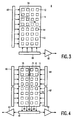
- Fig. 3 is a diagrammatic representation of a second embodiment of the photodetector of the exposure-control system of the X-ray examination apparatus shown in Fig. 1.
- the photodetector 9 of Fig. 3 comprises an intermediate memory 15 which forms part of the image pick-up section 11. Only a part 70 of the image pick-up section 11 is exposed.
- Fig. 3 shows an exposed area comprising only 2 ⁇ 2 elements 12, but in practice a region comprising 32 ⁇ 32 or 64 ⁇ 64 elements is preferably exposed. The number of elements exposed is much smaller than the total number of elements of the image pick-up section 11 (for example, 512 ⁇ 512 or 300 ⁇ 350).
- a GRIN lens having a short focal distance of, for example one millimetre and a high numerical aperture of from approximately 0.3 to 0.5, can be advantageously used to make light incident substantially exclusively on elements in the exposed part.
- the elements outside the exposed part are not exposed so that they can be used as the intermediate memory 15.
- Fig. 4 is a diagrammatic representation of a third embodiment of the photodetector of the exposure-control system of the X-ray examination apparatus shown in Fig. 1.
- the image memory 13 comprises two separate memory sections 81, 82 which are separated from one another by a barrier 83.
- the optical system is arranged so that the image picked up is imaged simultaneously onto two parts 70 and 71 of the image pick-up section.
- two GRIN lenses are used for this purpose.
- the photodetector comprises a plurality of row drivers 64, 65, 66 and 67 whereby electronic images formed in the separate parts of the image pick-up section can be independently transferred to the separate memory sections.
- the electronic image can be transferred from one of the parts of the image pick-up section to the other image memory section while the reading out of the first memory section continues.
- the parts of the image memory which are exposed by means of the optical system are chosen so that the images picked up are transferred to the relevant memory section by transporting electric charges along columns.
- the charges are transferred from the relevant memory section 81 or 82 to a read-out register 61 which forms an electronic signal which is converted into the primary image signal by means of an amplifier 62, which primary image signal is further amplified by the internal amplifier 32 of the image pick-up apparatus 6.
- the photodetector may comprise a second amplifier 63.
- Electronic images from respective memory sections can then be converted into primary electronic image signals by means of respective amplifiers 62 and 63.
- the separate memory sections can be read out partly simultaneously, so that at least one memory section is made available faster for a next electronic image.
- a photodetector comprising two sections which are separated by a barrier
Landscapes
- Health & Medical Sciences (AREA)
- General Health & Medical Sciences (AREA)
- Toxicology (AREA)
- Transforming Light Signals Into Electric Signals (AREA)
- Apparatus For Radiation Diagnosis (AREA)
- X-Ray Techniques (AREA)
Abstract
Claims (9)
- Appareil d'examen à rayons X (1) comprenantcaractérisé en ce queun détecteur à rayons X (5) pour convertir une image à rayons X en une image optique,un appareil de prise d'image (6) pour dériver un signal d'image à partir de l'image optique, etun système de commande d'exposition (7) comprenant- un photodétecteur (9) pour mesurer des valeurs de brillance de l'image optique et pour générer un signal de photodétecteur- lequel photodétecteur (9) comprendune section de prise d'image (11) etune section de stockage d'image (13, 15)le système de commande d'exposition (7) étant encore agencé de manière à- dériver un signal de commande à partir du signal de photodétecteur et- commander un niveau de signal du signal d'image sur la base du signal de commandela section de stockage d'image comprend une première section de stockage (13) et une seconde section de stockage (15) et est agencée de manière à recevoir des valeurs de brillance dans la première section de stockage (13), alors que des valeurs de brillance sont lues à partir de la seconde section de stockage (15).
- Appareil d'examen à rayons X selon la revendication 1, caractérisé en ce quela première section de stockage constitue une mémoire d'image (13) et en ce quela seconde section de stockage est conçue en tant qu'une mémoire intermédiaire (15) qui est couplée à la section de prise d'image et à la mémoire d'image.
- Appareil d'examen à rayons X selon la revendication 1, caractérisé en ce que la section de prise d'image (11) est couplée en charge à la mémoire intermédiaire (15).
- Appareil d'examen à rayons X selon la revendication 1, caractérisé en ce que la mémoire intermédiaire est couplée en charge à la mémoire d'image.
- Appareil d'examen à rayons X selon la revendication 1, caractérisé en ce que la mémoire intermédiaire (15) fait partie de la section de prise d'image (11).
- Appareil d'examen à rayons X selon la revendication 1, caractérisé en ce que le système de commande d'exposition (7) comprend un système optique (16) pour représenter au moins une partie de l'image optique sur pas plus d'une partie de la section de prise d'image (11).
- Appareil d'examen à rayons X selon la revendication 1, caractérisé en ce que le système optique comprend une lentille à gradient d'indice (GRIN) (16).
- Appareil d'examen à rayons X selon la revendication 1, caractérisé en ce que le système de commande d'exposition est agencé de manière à appliquer le signal de commande à la source à rayons X (2) ou à l'alimentation haute tension (17) de la source à rayons X.
- Appareil d'examen à rayons X selon la revendication 1, caractérisé en ce que le système de commande d'exposition est agencé de manière à appliquer le signal de commande à une unité de commande (32) ou à un diaphragme de l'appareil de prise d'image.
Priority Applications (1)
| Application Number | Priority Date | Filing Date | Title |
|---|---|---|---|
| EP96930335A EP0796549B1 (fr) | 1995-10-10 | 1996-10-02 | Appareil d'examen par rayons x comprenant un systeme de commande de l'exposition |
Applications Claiming Priority (4)
| Application Number | Priority Date | Filing Date | Title |
|---|---|---|---|
| EP95202719 | 1995-10-10 | ||
| EP95202719 | 1995-10-10 | ||
| PCT/IB1996/001037 WO1997014277A1 (fr) | 1995-10-10 | 1996-10-02 | Appareil d'examen aux rayons x comprenant un systeme de commande de l'exposition |
| EP96930335A EP0796549B1 (fr) | 1995-10-10 | 1996-10-02 | Appareil d'examen par rayons x comprenant un systeme de commande de l'exposition |
Publications (2)
| Publication Number | Publication Date |
|---|---|
| EP0796549A1 EP0796549A1 (fr) | 1997-09-24 |
| EP0796549B1 true EP0796549B1 (fr) | 2004-01-07 |
Family
ID=8220703
Family Applications (1)
| Application Number | Title | Priority Date | Filing Date |
|---|---|---|---|
| EP96930335A Expired - Lifetime EP0796549B1 (fr) | 1995-10-10 | 1996-10-02 | Appareil d'examen par rayons x comprenant un systeme de commande de l'exposition |
Country Status (5)
| Country | Link |
|---|---|
| US (1) | US5710801A (fr) |
| EP (1) | EP0796549B1 (fr) |
| JP (1) | JPH10511222A (fr) |
| DE (1) | DE69631283T2 (fr) |
| WO (1) | WO1997014277A1 (fr) |
Families Citing this family (18)
| Publication number | Priority date | Publication date | Assignee | Title |
|---|---|---|---|---|
| JPH11508109A (ja) * | 1996-03-27 | 1999-07-13 | コーニンクレッカ フィリップス エレクトロニクス エヌ ヴィ | 露出制御システムを含むx線検査装置及び画像ピックアップ装置の増幅器を制御する方法 |
| JP3869083B2 (ja) * | 1996-12-10 | 2007-01-17 | 株式会社モリタ製作所 | X線撮影装置 |
| EP0914755B1 (fr) * | 1997-04-24 | 2003-06-04 | Koninklijke Philips Electronics N.V. | Commande d'exposition sur la base d'une partie pertinente d'une image de radiographie x. |
| FR2768044B1 (fr) * | 1997-09-08 | 2000-06-02 | Morita Mfg | Appareil d'imagerie par rayons x |
| JP3554172B2 (ja) * | 1998-01-09 | 2004-08-18 | キヤノン株式会社 | 放射線撮影装置 |
| WO1999043152A2 (fr) * | 1998-02-23 | 1999-08-26 | Koninklijke Philips Electronics N.V. | Appareil d'examen au rayons-x avec commande d'exposition |
| DE69913311T2 (de) * | 1998-10-19 | 2004-10-14 | Koninklijke Philips Electronics N.V. | Röntgenuntersuchungsvorrichtung mit regelung der strahlendosis |
| JP2002532837A (ja) * | 1998-12-08 | 2002-10-02 | コーニンクレッカ フィリップス エレクトロニクス エヌ ヴィ | 対象物の吸収率に依存した輝度制御を含むx線検査装置 |
| WO2000038417A1 (fr) * | 1998-12-22 | 2000-06-29 | Koninklijke Philips Electronics N.V. | Procede et dispositif de formation de l'image d'un objet a partir d'une pluralite d'images |
| WO2001039558A1 (fr) * | 1999-11-23 | 2001-05-31 | Koninklijke Philips Electronics N.V. | Appareil d'examen aux rayons x comprenant un systeme de commande d'exposition |
| CN1331022C (zh) * | 2000-03-31 | 2007-08-08 | 皇家菲利浦电子有限公司 | 用于获取辐射图像的系统和方法 |
| FR2825816B1 (fr) * | 2001-06-08 | 2004-07-23 | Ge Med Sys Global Tech Co Llc | Procede d'affichage d'images d'organes |
| US6795526B2 (en) * | 2002-03-04 | 2004-09-21 | Ge Medical Systems Global Technology Co., Llc | Automatic exposure control for a digital image acquisition system |
| DE102005017489A1 (de) * | 2005-04-15 | 2006-10-19 | Siemens Ag | Verfahren zum Regeln der Dosis oder der Dosisleistung beim Aufnehmen von Röntgenbildern |
| US7830045B1 (en) * | 2009-03-27 | 2010-11-09 | Vinculums Services, Inc. | Rapid disconnect system for cellular tower transmissions |
| US9031195B2 (en) * | 2011-05-20 | 2015-05-12 | General Electric Company | Imaging detector and methods for image detection |
| DE102012216269A1 (de) * | 2012-09-13 | 2014-03-13 | Siemens Aktiengesellschaft | Röntgensystem und Verfahren zur Erzeugung von Bilddaten |
| JP6577700B2 (ja) * | 2014-06-30 | 2019-09-18 | キヤノン株式会社 | 放射線検出装置、その制御方法、放射線撮影装置、およびプログラム |
Family Cites Families (10)
| Publication number | Priority date | Publication date | Assignee | Title |
|---|---|---|---|---|
| NL8202418A (nl) * | 1982-06-15 | 1984-01-02 | Philips Nv | Roentgenonderzoekapparaat. |
| US4991102A (en) * | 1987-07-09 | 1991-02-05 | Hitachi, Ltd. | Engine control system using learning control |
| US5101421A (en) * | 1988-06-02 | 1992-03-31 | Kabushiki Kaisha Toshiba | X-ray imaging apparatus |
| JPH0458498A (ja) * | 1990-06-25 | 1992-02-25 | Toshiba Corp | X線診断装置 |
| EP0480096B1 (fr) * | 1990-10-12 | 1994-07-13 | Siemens Aktiengesellschaft | Appareil pour diagnostic aux rayons X comprenant un intensificateur d'image à rayons X et un détecteur de brillance d'image sur son écran de sortie |
| DE4300828C1 (de) * | 1993-01-14 | 1994-04-21 | Siemens Ag | Fernsehaufnahmeeinrichtung mit Halbleiter-Bildwandler |
| US5461658A (en) * | 1993-05-21 | 1995-10-24 | U.S. Philips Corporation | X-ray examination apparatus |
| EP0629105B1 (fr) * | 1993-05-21 | 1999-08-04 | Koninklijke Philips Electronics N.V. | Dispositif d'examen utilisant les rayons X et système de detection d'une image visible pour un dispositif d'examen utilisant les rayons X |
| JPH07312297A (ja) * | 1993-09-20 | 1995-11-28 | Philips Electron Nv | X線診断装置 |
| BE1007674A3 (nl) * | 1993-10-28 | 1995-09-12 | Philips Electronics Nv | Röntgenonderzoekapparaat. |
-
1996
- 1996-10-02 EP EP96930335A patent/EP0796549B1/fr not_active Expired - Lifetime
- 1996-10-02 WO PCT/IB1996/001037 patent/WO1997014277A1/fr not_active Ceased
- 1996-10-02 JP JP9514863A patent/JPH10511222A/ja not_active Ceased
- 1996-10-02 DE DE69631283T patent/DE69631283T2/de not_active Expired - Fee Related
- 1996-10-09 US US08/728,116 patent/US5710801A/en not_active Expired - Fee Related
Also Published As
| Publication number | Publication date |
|---|---|
| US5710801A (en) | 1998-01-20 |
| DE69631283D1 (de) | 2004-02-12 |
| EP0796549A1 (fr) | 1997-09-24 |
| JPH10511222A (ja) | 1998-10-27 |
| WO1997014277A1 (fr) | 1997-04-17 |
| DE69631283T2 (de) | 2004-10-14 |
Similar Documents
| Publication | Publication Date | Title |
|---|---|---|
| EP0796549B1 (fr) | Appareil d'examen par rayons x comprenant un systeme de commande de l'exposition | |
| US6333963B1 (en) | Image sensing apparatus and method | |
| US6163386A (en) | Photoelectric conversion device and driving method therefor | |
| US6028913A (en) | X-ray examination apparatus including an image sensor matrix with a correction unit | |
| US20050285043A1 (en) | X-ray detector array for both imgaging and measuring dose | |
| US5790629A (en) | Apparatus for making x-ray images | |
| EP0909527B1 (fr) | Appareil d'examen aux rayons x comprenant un systeme de commande d'exposition | |
| US5710428A (en) | Infrared focal plane array detecting apparatus having light emitting devices and infrared camera adopting the same | |
| NL8701169A (nl) | Beeldopneem- en -weergeefstelsel en hiervoor geschikte beeldopneeminrichting. | |
| US5530935A (en) | X-ray examination apparatus | |
| US5955725A (en) | Digitizing CCD array system | |
| US6226351B1 (en) | X-ray examination apparatus with a high-resolution image sensor | |
| US6084940A (en) | Exposure control on the basis of a relevant part of an X-ray image | |
| JPH0415679B2 (fr) | ||
| US6198801B1 (en) | X-ray examination apparatus including exposure control | |
| EP0740883B1 (fr) | Appareil de prise d'images | |
| JPH0575931A (ja) | 撮像装置 | |
| EP0644712A1 (fr) | Appareil d'examen à rayons X | |
| WO1999048286A2 (fr) | Appareil de prise de vues comprenant une unite de correction | |
| JPH06217963A (ja) | X線診断装置 | |
| JPH11155848A (ja) | X線画像撮影方法及びx線画像撮影装置 | |
| JPS6345219B2 (fr) | ||
| JPH0616775B2 (ja) | X線診断装置 | |
| Kamasz et al. | Advanced CCD linescan sensor for high-contrast film scanning | |
| JPH0475706B2 (fr) |
Legal Events
| Date | Code | Title | Description |
|---|---|---|---|
| PUAI | Public reference made under article 153(3) epc to a published international application that has entered the european phase |
Free format text: ORIGINAL CODE: 0009012 |
|
| AK | Designated contracting states |
Kind code of ref document: A1 Designated state(s): DE FR GB NL |
|
| 17P | Request for examination filed |
Effective date: 19971017 |
|
| 17Q | First examination report despatched |
Effective date: 20020705 |
|
| GRAH | Despatch of communication of intention to grant a patent |
Free format text: ORIGINAL CODE: EPIDOS IGRA |
|
| GRAS | Grant fee paid |
Free format text: ORIGINAL CODE: EPIDOSNIGR3 |
|
| GRAA | (expected) grant |
Free format text: ORIGINAL CODE: 0009210 |
|
| AK | Designated contracting states |
Kind code of ref document: B1 Designated state(s): DE FR GB NL |
|
| PG25 | Lapsed in a contracting state [announced via postgrant information from national office to epo] |
Ref country code: NL Free format text: LAPSE BECAUSE OF FAILURE TO SUBMIT A TRANSLATION OF THE DESCRIPTION OR TO PAY THE FEE WITHIN THE PRESCRIBED TIME-LIMIT Effective date: 20040107 Ref country code: FR Free format text: LAPSE BECAUSE OF FAILURE TO SUBMIT A TRANSLATION OF THE DESCRIPTION OR TO PAY THE FEE WITHIN THE PRESCRIBED TIME-LIMIT Effective date: 20040107 |
|
| REG | Reference to a national code |
Ref country code: GB Ref legal event code: FG4D |
|
| REG | Reference to a national code |
Ref country code: GB Ref legal event code: 746 Effective date: 20040109 |
|
| REF | Corresponds to: |
Ref document number: 69631283 Country of ref document: DE Date of ref document: 20040212 Kind code of ref document: P |
|
| NLV1 | Nl: lapsed or annulled due to failure to fulfill the requirements of art. 29p and 29m of the patents act | ||
| PG25 | Lapsed in a contracting state [announced via postgrant information from national office to epo] |
Ref country code: GB Free format text: LAPSE BECAUSE OF NON-PAYMENT OF DUE FEES Effective date: 20041002 |
|
| PLBE | No opposition filed within time limit |
Free format text: ORIGINAL CODE: 0009261 |
|
| STAA | Information on the status of an ep patent application or granted ep patent |
Free format text: STATUS: NO OPPOSITION FILED WITHIN TIME LIMIT |
|
| 26N | No opposition filed |
Effective date: 20041008 |
|
| EN | Fr: translation not filed | ||
| PG25 | Lapsed in a contracting state [announced via postgrant information from national office to epo] |
Ref country code: DE Free format text: LAPSE BECAUSE OF NON-PAYMENT OF DUE FEES Effective date: 20050503 |
|
| GBPC | Gb: european patent ceased through non-payment of renewal fee |
Effective date: 20041002 |