EP0796553B1 - Semoir, en particulier pour semis en paillage - Google Patents
Semoir, en particulier pour semis en paillage Download PDFInfo
- Publication number
- EP0796553B1 EP0796553B1 EP96120221A EP96120221A EP0796553B1 EP 0796553 B1 EP0796553 B1 EP 0796553B1 EP 96120221 A EP96120221 A EP 96120221A EP 96120221 A EP96120221 A EP 96120221A EP 0796553 B1 EP0796553 B1 EP 0796553B1
- Authority
- EP
- European Patent Office
- Prior art keywords
- sowing
- machine according
- sowing machine
- share
- shares
- Prior art date
- Legal status (The legal status is an assumption and is not a legal conclusion. Google has not performed a legal analysis and makes no representation as to the accuracy of the status listed.)
- Expired - Lifetime
Links
- 238000009331 sowing Methods 0.000 title claims description 64
- 239000002362 mulch Substances 0.000 title description 6
- 238000010899 nucleation Methods 0.000 title 1
- 239000002689 soil Substances 0.000 claims description 8
- 238000003971 tillage Methods 0.000 description 4
- 230000015572 biosynthetic process Effects 0.000 description 1
- 230000000052 comparative effect Effects 0.000 description 1
- 230000008878 coupling Effects 0.000 description 1
- 238000010168 coupling process Methods 0.000 description 1
- 238000005859 coupling reaction Methods 0.000 description 1
- 238000010348 incorporation Methods 0.000 description 1
- 230000009191 jumping Effects 0.000 description 1
- 238000000034 method Methods 0.000 description 1
- 210000000056 organ Anatomy 0.000 description 1
- 238000012805 post-processing Methods 0.000 description 1
- 238000007711 solidification Methods 0.000 description 1
- 230000008023 solidification Effects 0.000 description 1
Images


Classifications
-
- A—HUMAN NECESSITIES
- A01—AGRICULTURE; FORESTRY; ANIMAL HUSBANDRY; HUNTING; TRAPPING; FISHING
- A01C—PLANTING; SOWING; FERTILISING
- A01C7/00—Sowing
- A01C7/20—Parts of seeders for conducting and depositing seed
- A01C7/201—Mounting of the seeding tools
- A01C7/203—Mounting of the seeding tools comprising depth regulation means
-
- A—HUMAN NECESSITIES
- A01—AGRICULTURE; FORESTRY; ANIMAL HUSBANDRY; HUNTING; TRAPPING; FISHING
- A01B—SOIL WORKING IN AGRICULTURE OR FORESTRY; PARTS, DETAILS, OR ACCESSORIES OF AGRICULTURAL MACHINES OR IMPLEMENTS, IN GENERAL
- A01B49/00—Combined machines
- A01B49/04—Combinations of soil-working tools with non-soil-working tools, e.g. planting tools
- A01B49/06—Combinations of soil-working tools with non-soil-working tools, e.g. planting tools for sowing or fertilising
Definitions
- the invention relates to a seed drill with a frame, on the one hand for the connection to a leading one Depth guidance device and on the other hand for the attachment and mounting of coulters and serves a share disc assigned to each coulter, with the coulters in the working area of the coulter discs are arranged.
- Seeders of the type mentioned are from WO-85/05246 known.
- This document shows a seeder whose frame carries a seed hopper, where the frame of the seeder via a coupling to one Tractor can be attached.
- the depth control of this seeder is firstly due to the requirement for the tractor and on the other hand by a downstream roller unit causes, which consists of individual pressure rollers.
- the coulters work together with disc coulters, whereby the disc coulters inclined when viewed in the direction of travel be so that for the following coulters a furrow is cleared in which the seeds are deposited becomes.
- the furrow is then closed and solidified by means of the pressure rollers.
- the pressure rollers as such are height-adjustable independently of one another arranged so that bumps across can be compensated for the direction of travel.
- These well-known Seeders are complex to construct. It also turns out to be very good with these seeders disadvantageous that they require a downstream roller. The latter can occur with moist, sticky soil pick up the seeds again by sticking and so controlled seed placement is impossible do.
- the invention has for its object a seed drill of the type mentioned in such a way that this with high driving speeds at a more even Can be operated, a mulch sowing and at the same time allows a good incorporation of mulch, easy to set up and either solo or with any Soil cultivation combinations can be operated in combination is.
- the seeder is with a frame trained, the connection means with which the Seeder rigidly attached to a leading depth control device, for example a roller, e.g. B. one or Multi-row packer star roller, for example with Roller elements according to DE-OS 35 41 542, or a tooth packer roller, or support wheels can also be connected is.
- a leading depth control device for example a roller, e.g. B. one or Multi-row packer star roller, for example with Roller elements according to DE-OS 35 41 542, or a tooth packer roller, or support wheels can also be connected is.
- This roller can be part of a tillage combination be, for example one Compact harrow, a rotary harrow, a tiller. In front These cultivators can use other cultivators etc. are used.
- This rigid with the leading one Depth guide device has detachable frames a cross member running transverse to the direction of travel on which the interacting coulter disks and Coulters are attached.
- coulters and coulter discs are each attached to a holding arm, which in turn is connected to a beam that is connected to the Cross member is connectable.
- This arranged on the beam Unit consisting of coulter disc and coulter is advantageous with a detachable fastener on the Cross member attached so that the number of coulters as well as their distance from each other in a simple manner is variable.
- the two holding arms are advantageously attached to a beam in such a way that the associated coulters and coulter discs offset relative to the beam in the direction of travel are arranged.
- the holding arms are advantageous Coulters and coulter discs each on one side of the Arranged bar, so that this already the necessary maintain lateral distance for the furrow width becomes. This unit can be completely on the cross member attached and connected at any point become.
- the coulters as such are advantageous at an angle of 10 to 20 ° to the vertical and are moreover essentially advantageous in Direction of travel arranged. Because of this inclination the coulter discs loosen the soil, so that the next to or in the work area behind the coulters already arranged in a coulter intervene in loosened soil. Mulch etc. cut through the coulter discs and pushed to the side, so that the furrow drawing and the sowing process is not hindered by the mulch.
- the frame on the leading Depth control device becomes a low-vibration Attachment of the coulters and coulter discs achieved, so that the facility with a comparative can be operated at high speed.
- the coulter disks are mutually reciprocal inclined to the vertical, so that internal forces the frame be balanced, which is equally to Calms the run of the seeder and thus also to an even higher speed.
- the holding arms are the cause of soil for each coulter and each coulter disc articulated on Arranged bars, the working position by a preloaded spring is maintained. At normal load of coulter disc and coulter this is in their End position held. Only with overload, the one Fear the coulter disc or coulter leaves, there is an evasion upwards.
- the bar to which the coulters are attached can be advantageous are, via a parallel link unit on the Cross members are connected, here a spring ensures that the bar in the working position against a stop is pressed, which is the working position Are defined.
- a spring ensures that the bar in the working position against a stop is pressed, which is the working position Are defined.
- This trailing wheel or trailing roller serves on the one hand to reconsolidate the furrow or Furrows and on the other hand it has the task of a fine adjustment to ensure for the depth guidance.
- the wheel follows the ground contour so that the sowing organs maintain their pre-selected working depth. This is a very high accuracy reached with regard to the placement depth of the seed. This is particularly advantageous for bumps, etc. This fine adjustment alike a jumping etc. prevented, so that the seeder with a steady, high speed even at Bumps can be operated.
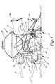
- FIG. 1 shows a tillage combination with an inventive seeder 1, the rigidly attached to a leading tillage combination via its frame 2 3 is connected, which consists of a Depth guide roller 4 and a rotary harrow 5.
- the rotary harrow 5 is connected to the top link 6 or Lower link 7 of a tractor, not shown, can be connected.
- the frame 2 of the tillage machine is about lower Fasteners 8 and top fasteners 9 rigid with the headstock 10 of the rotary harrow 5 connected.
- This headstock has lower link connections 11 and a top link 12.
- the frame 2 consists of an angular part 13 and two parallel links 14, 15 on the one hand a fastening part 16 and on the other hand on an arm 17 are connected, the two handlebars with each other combines. This creates a four-bar guide for get the arm 17.
- the fixation of the parallel link unit 14, 15 including the arm 17 relative to the angular part 13 takes place via a turnbuckle 18.
- a hydraulic cylinder can also be used 18a are used, the adjustment the working depth of the sowing unit 19 is facilitated.
- the turnbuckle 18 or the hydraulic Cylinder 18a becomes the working depth of the sowing unit 19 relative to the leading depth control device 4 set.
- the rotary harrow 5 in turn is supported including its trestle 10 on an arm 20 the roller 4.
- the position of the rotary harrow 5 relative to this arm and thus to the depth control device 4 is set by bolts 21 which are in different Holes of the rotary harrow 5 can be inserted. hereby is also the working depth of the sowing unit 19 adjusted.
- FIGS. 2a and 2b Scale On the arm 17 of the seeder 1 there is a crossbar 22 attached, which is enlarged in FIGS. 2a and 2b Scale is shown. At this crossbar are the sowing units 19 are fastened by means of screw tapes 23. These screw tapes reach through perpendicular to that Cross member 22 extending beam 24, the Tensioning by nuts 25 takes place.
- each beam 24 there are holding arms 26 on both sides and 27 pivotally articulated by means of a pivot 28.
- On each bar are the respective holding arms 26, 27 assigned, stops 29 attached in the form of bolts, which determine the working position of the Holding arms 26, 27 serve.
- a spring 30 To fix this working position serves a spring 30, the one hand on the holding arm 26, 27 and on the other hand attached to the beam 24 is. This spring is biased so that with normal Operation of the holding arms at their respective stops 29 rest on the beam 24. Only occurs when there is an overload Swiveling the holding arms counterclockwise a so that damage to the sowing unit 19 is avoided become.
- the sowing unit 19 consists of several each one Double unit combined coulters 31 and Coulter disks 32, both on a common holding arm 26, 27 are arranged.
- Each coulter has one Share body 33 and a share point 42.
- Each a holding arm 26, 27 is on one side of the beam 24 arranged.
- the coulter disks 32 are against each other directed, with their lower ends, the coulters 31 on the inside of each Coulter disks are arranged. Through the inclination the coulter discs with 10 to 20 ° will loosen well of the ground, with the coulters in loosened area of the ground. Through this relatively strong inclination of the coulter discs the coulter disc also essentially in Direction of travel can be aligned, which advantages in terms on the working resistance.
- a post-processing device 55 can be provided, for example Weeder to even out the seedbed.
- the seed hopper 34 attached to the frame 2 of the seeder 1.
- the seed hopper it is also conceivable to use the seed hopper to be provided elsewhere, for example by the Use of a front seed hopper.
- FIG. 3 shows the possible combinations in which a seeder can be used according to the invention can.
- a cultivator 37 is connected to the front connection points 36 become.
- a Packer 38 are provided to the seeder 1 with a star wheel 39 become.
- a pressure roller 40 or a harrow device 41 can be arranged downstream of the sowing units.
- the seed drill 1 leading device can either a compact harrow 42, a rotary harrow 5, a tiller 43 or in the simplest case only support wheels 44 are provided.
- the seeder can 1 with the support wheels 44 to the tractor 35 be connected.
- Fig. 4 shows a further embodiment according to the Invention, in which the same parts with the same reference numerals are provided.
- This embodiment differs differs from that of FIG. 1 in the formation of the Sowing unit 19.
- This sowing unit 19 is on a larger scale shown in Figs. 5 and 6.
- the coulters 31 and the coulter discs 32 likewise via holding arms 26, 27 on the beam 24 connected in the same way as based on this 2a and 2b has been explained.
- the difference this embodiment is that the Beam 24 in turn via a pair of parallel links 45, 46 is connected to a beam 47, which in turn connected to the cross member 22 via screw tapes 23 is. This will cause a relative movement of the Bar 24 to the cross member 22 allows.
- roller element 48 On the bar 24 is a roller element 48 about a pivot axis 49 connected.
- An arm 50 on the beam 24 bridges the pivot axis 49 and has a spindle at its end 51 on that with the bracket 54 of the roller element 48 is connected and with which the relative position of the Roller element 48 for beam 24 is adjustable.
Landscapes
- Life Sciences & Earth Sciences (AREA)
- Soil Sciences (AREA)
- Environmental Sciences (AREA)
- Engineering & Computer Science (AREA)
- Mechanical Engineering (AREA)
- Soil Working Implements (AREA)
- Sowing (AREA)
- Photoreceptors In Electrophotography (AREA)
Claims (26)
- Semoir (1) comprenant un châssis (2) servant, d'une part, au rattachement à un dispositif de réglage vertical (4) situé à l'avant et, d'autre part, à la fixation et au support de socs de semoir (31) ainsi que des disques ouvreurs (32) associés chacun à un soc de semoir (31), lesdits socs de semoir (31) étant disposés dans le rayon d'action des disques ouvreurs (32), caractérisé en ce que le châssis (2) présente des moyens de rattachement (8, 9) servant à rattacher de manière rigide le châssis (2) au dispositif de réglage vertical (4), en ce que le châssis (2) présente un support transversal (22) s'étendant essentiellement transversalement au sens de déplacement et servant à la fixation des socs de semoir (31) et des disques ouvreurs (32), en ce qu'un soc de semoir (31) et un disque ouvreur (32) sont fixés respectivement à un bras porteur (26, 27), en ce que deux socs de semoir (31) et deux disques ouvreurs (32) sont fixés, avec leurs bras porteurs respectifs (26, 27), à une poutre (24), laquelle est rattachée au support transversal (22) du châssis (2) et s'étend perpendiculairement à celui-ci.
- Semoir selon la revendication 1, caractérisé en ce que les socs de semoir (31) sont disposés latéralement par rapport aux disques ouvreurs (32) au voisinage de ceux-ci.
- Semoir selon la revendication 1 ou 2, caractérisé en ce que les disques ouvreurs (32) présentent une inclinaison de 10 à 20° par rapport à la verticale.
- Semoir selon l'une des revendications 1 à 3, caractérisé en ce que chaque bras porteur (26, 27) supportant les socs de semoir (31) et les disques ouvreurs (32) est articulé sur le châssis (2) autour d'un axe de pivotement (28), le mouvement pivotant n'intervenant que lors du dépassement d'une charge prédéfinie.
- Semoir selon la revendication 4, caractérisé en ce que les socs de semoir (31) et les disques ouvreurs (32) sont sollicités contre une butée (29) située sur la poutre (24) au moyen d'un ressort (30) tendu.
- Semoir selon la revendication 4 ou 5, caractérisé en ce que les socs de semoir (31) et les disques ouvreurs (32) sont fixés sur le même bras porteur (26, 27).
- Semoir selon la revendication 6, caractérisé en ce que les bras porteurs (26, 27) supportant les socs de semoir (31) et les disques ouvreurs (32) sont fixés respectivement de part et d'autre de la poutre (24), décalés avantageusement les uns par rapport aux autres dans la direction longitudinale.
- Semoir selon l'une des revendications 6 à 7, caractérisé en ce que les disques ouvreurs (32) fixés sur une même poutre (24) sont rapprochés l'un de l'autre soit à leur partie inférieure, soit à leur partie supérieure.
- Semoir selon l'une des revendications 6 à 8, caractérisé en ce que les socs de semoir (31) fixés sur une même poutre (24) se trouvent soit du côté où les disques ouvreurs (32) sont rapprochés l'un de l'autre, soit du côté où ils sont écartés l'un de l'autre.
- Semoir selon l'une des revendications 1 à 9, caractérisé en ce que le support transversal (22) du châssis (2), y compris la poutre (24) supportant les socs de semoir (31) et les disques ouvreurs (32), est réglable en hauteur par rapport aux autres parties du châssis (13, 22) à l'aide, par exemple, d'un tendeur (18) ou d'un vérin hydraulique (18a).
- Semoir selon la revendication 10, caractérisé en ce que la poutre transversale (22) est relié aux autres parties du châssis au moyen d'une tringlerie formant parallélogramme (14, 15).
- Semoir selon l'une des revendications 1 à 11, caractérisé en ce que la poutre transversale (22) est segmentée sur toute la largeur de travail du semoir.
- Semoir selon l'une des revendications 1 à 12, caractérisé en ce que le dispositif de réglage vertical (4) est composé d'un rouleau.
- Semoir selon la revendication 13, caractérisé en ce que le rouleau présente la forme d'un rouleau tasseur étoilé à une seule rangée ou à plusieurs rangées.
- Semoir selon la revendication 13 ou 14, caractérisé en ce que le rouleau est associé à une machine de préparation du sol telle qu'une herse centrifuge, une fraiseuse de labour etc.
- Semoir selon l'une des revendications 13 à 15, caractérisé en ce que le rouleau est segmenté sur toute sa largeur de travail.
- Semoir selon l'une des revendications 1 à 16, caractérisé en ce que la trémie à semences (34) du semoir (1) est fixée sur le châssis (2).
- Semoir selon l'une des revendications 1 à 17, caractérisé en ce qu'un élément de rouleau (48) est placé en aval de chaque poutre (24) du châssis (2) du semoir (1).
- Semoir selon l'une des revendications 1 à 17, caractérisé en ce qu'un élément de rouleau commun est placé en aval de plusieurs poutres (24) adjacentes.
- Semoir selon la revendication 18 ou 19, caractérisé en ce que la ou les poutres (24) est (sont) rattachée(s) au support transversal (22) par l'intermédiaire d'une unité à bras oscillants parallèles (45, 46).
- Semoir selon la revendication 20, caractérisé en ce qu'un ressort tendu (53) est intercalé entre le support tyransversal (22) et la ou les poutres (24), lequel maintient la ou les poutres (24) en position de travail tout en chargeant l'élément de rouleau (48).
- Semoir selon l'une des revendications 1 à 21, caractérisé en ce que les disques ouvreurs (32) présentent une circonférence onduleuse ou crénelée.
- Semoir selon l'une des revendications 1 à 22, caractérisé en ce que les disques ouvreurs (32) sont bombés.
- Semoir selon l'une des revendications 1 à 23, caractérisé en ce qu'une machine supplémentaire de travail du sol (55), telle qu'une étrille ou un rouleau de pression, est placée en aval des socs de semoir (31) et des disques ouvreurs (32).
- Semoir selon la revendication 24, caractérisé en ce que la machine supplémentaire de travail du sol (55) est segmentée sur toute sa largeur de travail.
- Semoir selon l'une des revendications 1 à 25, caractérisé en ce que les bras porteurs (26, 27) sont inclinés vers l'arrière selon un angle de 0 à 25° par rapport à la verticale.
Applications Claiming Priority (2)
| Application Number | Priority Date | Filing Date | Title |
|---|---|---|---|
| DE29605356U | 1996-03-22 | ||
| DE29605356U DE29605356U1 (de) | 1996-03-22 | 1996-03-22 | Sägerät, insbesondere für Mulchsaat |
Publications (3)
| Publication Number | Publication Date |
|---|---|
| EP0796553A2 EP0796553A2 (fr) | 1997-09-24 |
| EP0796553A3 EP0796553A3 (fr) | 1999-04-28 |
| EP0796553B1 true EP0796553B1 (fr) | 2003-03-12 |
Family
ID=8021531
Family Applications (1)
| Application Number | Title | Priority Date | Filing Date |
|---|---|---|---|
| EP96120221A Expired - Lifetime EP0796553B1 (fr) | 1996-03-22 | 1996-12-17 | Semoir, en particulier pour semis en paillage |
Country Status (2)
| Country | Link |
|---|---|
| EP (1) | EP0796553B1 (fr) |
| DE (2) | DE29605356U1 (fr) |
Families Citing this family (13)
| Publication number | Priority date | Publication date | Assignee | Title |
|---|---|---|---|---|
| GB9723293D0 (en) * | 1997-11-05 | 1998-01-07 | Kverneland Klepp As | Soil working implement |
| ATE285667T1 (de) * | 1999-05-26 | 2005-01-15 | Amazonen Werke Dreyer H | Säkombination |
| FR2851121B1 (fr) * | 2003-02-14 | 2006-01-06 | Michel Evin | Dechaumeuse de precision |
| DE20309687U1 (de) | 2003-06-24 | 2003-10-02 | Hendlmeier, Konrad, 93107 Thalmassing | Bodenbearbeitungsgerät |
| DE102004008089A1 (de) * | 2004-02-19 | 2005-09-08 | Rabe Agrarsysteme Gmbh & Co. Kg | Sävorrichtung, insbesondere für Mulchsaat |
| DE102005028030A1 (de) * | 2005-06-17 | 2007-01-04 | Amazonen-Werke H. Dreyer Gmbh & Co. Kg | Auf eine Bodenwalze aufgesattelte und einen Rahmen aufweisende Sämaschine |
| DE102006034798B4 (de) * | 2006-07-27 | 2014-02-13 | Alois Pöttinger Maschinenfabrik Gmbh | Landmaschine |
| DE502007003713D1 (de) * | 2006-10-14 | 2010-06-24 | Lemken Gmbh & Co Kg | Doppelscheibenschar mit Tiefenführungsrolle und Schwenkmechanismus |
| DE102013017901A1 (de) | 2013-10-29 | 2015-04-30 | Rauch Landmaschinenfabrik Gmbh | Landwirtschaftliche Verteilmaschine |
| FR3012721B1 (fr) * | 2013-11-05 | 2016-12-30 | Alois Pottinger Maschf Gmbh | Machine de travail du sol |
| DE102014106889A1 (de) * | 2014-05-15 | 2015-11-19 | Horsch Maschinen Gmbh | Landwirtschaftliche Verteilmaschine, insbesondere Sämaschine, und Verfahren zur Höhenverstellung von Säscharen |
| CN107624290A (zh) * | 2017-10-27 | 2018-01-26 | 朴万寿 | 覆土铺膜直播机 |
| CN108142048A (zh) * | 2018-03-26 | 2018-06-12 | 王友芳 | 带硬质导种管的玉米播种机 |
Family Cites Families (9)
| Publication number | Priority date | Publication date | Assignee | Title |
|---|---|---|---|---|
| FR65716E (fr) * | 1941-06-20 | 1956-03-12 | Dispositif pour culture sur terres battantes et mode d'utilisation | |
| US4116140A (en) * | 1976-12-09 | 1978-09-26 | Haybuster Manufacturing, Inc. | Press wheel depth control for grain drill furrow openers |
| GB2011236B (en) * | 1977-12-21 | 1982-04-07 | Ici Ltd | Coulter device for directz seed drills |
| EP0218585A1 (fr) * | 1984-05-21 | 1987-04-22 | Väderstadverken Ab | Appareil pour machines agricoles de distribution |
| DE3541542A1 (de) | 1985-11-25 | 1987-05-27 | Fritz Guettler | Teilringe fuer ackerwalze, wie stern-oder prismen-oder ringelwalze und andere |
| GB2222756B (en) * | 1988-09-20 | 1992-08-12 | Samuel Moore | Improved method and means for agricultural seeding |
| NZ237288A (en) * | 1991-03-01 | 1994-11-25 | Massey University Substituted | Seed sower with rotatable ground-slitting blade and scraper therefor: sub-surface tine forms horizontal slot for seed deposition |
| DE9213091U1 (de) * | 1992-09-29 | 1992-11-26 | Rabewerk GmbH + Co, 4515 Bad Essen | Kreiselegge |
| US5398771A (en) * | 1993-02-23 | 1995-03-21 | Crustbuster/Speed King, Inc. | Grain Drill |
-
1996
- 1996-03-22 DE DE29605356U patent/DE29605356U1/de not_active Expired - Lifetime
- 1996-12-17 DE DE59610222T patent/DE59610222D1/de not_active Expired - Lifetime
- 1996-12-17 EP EP96120221A patent/EP0796553B1/fr not_active Expired - Lifetime
Also Published As
| Publication number | Publication date |
|---|---|
| EP0796553A2 (fr) | 1997-09-24 |
| DE59610222D1 (de) | 2003-04-17 |
| EP0796553A3 (fr) | 1999-04-28 |
| DE29605356U1 (de) | 1997-07-17 |
Similar Documents
| Publication | Publication Date | Title |
|---|---|---|
| EP2949192B1 (fr) | Charrue dotée de plusieurs corps de labour disposés sur une flèche de charrue | |
| DE60037458T3 (de) | Landwirtschaftliches Gerät | |
| EP0407896B1 (fr) | Dispositif de travail du sol pour cultures en lignes | |
| EP0796553B1 (fr) | Semoir, en particulier pour semis en paillage | |
| EP0062734B1 (fr) | Charrue avec ligne de force de la coupe et point d'attache de traction réglable | |
| EP0070396A1 (fr) | Cultivateur pour travail profond ayant des rouleaux coopérant avec les outils de travail | |
| EP0426960A2 (fr) | Bineuse pour machine agricole | |
| DE2616545A1 (de) | Wurzel- und stengelshredder | |
| EP1391147B1 (fr) | Soc d'ensemencement avec des socs de semoir échelonnés suivis de rouleaux de pression | |
| DE102021102507B4 (de) | Bodenbearbeitungsgerät | |
| DE102021107169B4 (de) | Bodenbearbeitungsgerät | |
| EP1951024B1 (fr) | Appareil de traitement du sol dote d'une protection de manivelle | |
| AT391050B (de) | Kombinationsgeraet zur landwirtschaftlichen bodenbearbeitung | |
| DE3343847C2 (fr) | ||
| DE3422254A1 (de) | Bodenbearbeitungsmaschine, insbesondere kreiselegge zur saatbettbereitung | |
| EP0486473A1 (fr) | Machine agricole de préparation du sol | |
| DE2515767A1 (de) | Saatbeetaufbereitungsgeraet | |
| CH662701A5 (de) | Kombinationsgeraet zur landwirtschaftlichen bodenbearbeitung. | |
| DE102020133571B4 (de) | Bodenbearbeitungsgerät | |
| EP0445582B1 (fr) | Machine pour travailler le sol | |
| DE3501535A1 (de) | Bodenbearbeitungsmaschine | |
| DE69012976T2 (de) | Bodenbearbeitungsmaschine. | |
| EP0359896B1 (fr) | Machine combinée | |
| EP0445583B1 (fr) | Machine pour travailler le sol | |
| DE69000892T2 (de) | Verbesserung an einem Säsystem, Sämaschine und kombinierte Maschine zur Saatbettherrichtung und zum Säen mit einem solchen Säsystem. |
Legal Events
| Date | Code | Title | Description |
|---|---|---|---|
| PUAI | Public reference made under article 153(3) epc to a published international application that has entered the european phase |
Free format text: ORIGINAL CODE: 0009012 |
|
| AK | Designated contracting states |
Kind code of ref document: A2 Designated state(s): DE FR |
|
| PUAL | Search report despatched |
Free format text: ORIGINAL CODE: 0009013 |
|
| AK | Designated contracting states |
Kind code of ref document: A3 Designated state(s): DE FR |
|
| 17P | Request for examination filed |
Effective date: 19990819 |
|
| 17Q | First examination report despatched |
Effective date: 19991013 |
|
| GRAG | Despatch of communication of intention to grant |
Free format text: ORIGINAL CODE: EPIDOS AGRA |
|
| GRAG | Despatch of communication of intention to grant |
Free format text: ORIGINAL CODE: EPIDOS AGRA |
|
| GRAH | Despatch of communication of intention to grant a patent |
Free format text: ORIGINAL CODE: EPIDOS IGRA |
|
| RAP1 | Party data changed (applicant data changed or rights of an application transferred) |
Owner name: RABE AGRARSYSTEME GMBH & CO. KG |
|
| GRAH | Despatch of communication of intention to grant a patent |
Free format text: ORIGINAL CODE: EPIDOS IGRA |
|
| GRAA | (expected) grant |
Free format text: ORIGINAL CODE: 0009210 |
|
| AK | Designated contracting states |
Designated state(s): DE FR |
|
| REF | Corresponds to: |
Ref document number: 59610222 Country of ref document: DE Date of ref document: 20030417 Kind code of ref document: P |
|
| ET | Fr: translation filed | ||
| PLBI | Opposition filed |
Free format text: ORIGINAL CODE: 0009260 |
|
| 26 | Opposition filed |
Opponent name: AMAZONEN-WERKEH. DREYER GMBH & CO. KG Effective date: 20031211 |
|
| PLAX | Notice of opposition and request to file observation + time limit sent |
Free format text: ORIGINAL CODE: EPIDOSNOBS2 |
|
| PLBP | Opposition withdrawn |
Free format text: ORIGINAL CODE: 0009264 |
|
| PLAX | Notice of opposition and request to file observation + time limit sent |
Free format text: ORIGINAL CODE: EPIDOSNOBS2 |
|
| PLBB | Reply of patent proprietor to notice(s) of opposition received |
Free format text: ORIGINAL CODE: EPIDOSNOBS3 |
|
| PLBD | Termination of opposition procedure: decision despatched |
Free format text: ORIGINAL CODE: EPIDOSNOPC1 |
|
| PLBM | Termination of opposition procedure: date of legal effect published |
Free format text: ORIGINAL CODE: 0009276 |
|
| STAA | Information on the status of an ep patent application or granted ep patent |
Free format text: STATUS: OPPOSITION PROCEDURE CLOSED |
|
| 27C | Opposition proceedings terminated |
Effective date: 20050114 |
|
| REG | Reference to a national code |
Ref country code: FR Ref legal event code: TP |
|
| PGFP | Annual fee paid to national office [announced via postgrant information from national office to epo] |
Ref country code: FR Payment date: 20100105 Year of fee payment: 14 |
|
| PGFP | Annual fee paid to national office [announced via postgrant information from national office to epo] |
Ref country code: DE Payment date: 20100225 Year of fee payment: 14 |
|
| REG | Reference to a national code |
Ref country code: FR Ref legal event code: ST Effective date: 20110831 |
|
| PG25 | Lapsed in a contracting state [announced via postgrant information from national office to epo] |
Ref country code: FR Free format text: LAPSE BECAUSE OF NON-PAYMENT OF DUE FEES Effective date: 20110103 |
|
| REG | Reference to a national code |
Ref country code: DE Ref legal event code: R119 Ref document number: 59610222 Country of ref document: DE Effective date: 20110701 |
|
| PG25 | Lapsed in a contracting state [announced via postgrant information from national office to epo] |
Ref country code: DE Free format text: LAPSE BECAUSE OF NON-PAYMENT OF DUE FEES Effective date: 20110701 |