EP0796576B1 - Mechanische Fernbedienungsanordnung mit Drucktastenschalter mit niedrigem Profil - Google Patents
Mechanische Fernbedienungsanordnung mit Drucktastenschalter mit niedrigem Profil Download PDFInfo
- Publication number
- EP0796576B1 EP0796576B1 EP97301856A EP97301856A EP0796576B1 EP 0796576 B1 EP0796576 B1 EP 0796576B1 EP 97301856 A EP97301856 A EP 97301856A EP 97301856 A EP97301856 A EP 97301856A EP 0796576 B1 EP0796576 B1 EP 0796576B1
- Authority
- EP
- European Patent Office
- Prior art keywords
- lever
- plunger
- wire
- actuator assembly
- sleeve
- Prior art date
- Legal status (The legal status is an assumption and is not a legal conclusion. Google has not performed a legal analysis and makes no representation as to the accuracy of the status listed.)
- Expired - Lifetime
Links
- 230000000994 depressogenic effect Effects 0.000 claims description 9
- 230000009471 action Effects 0.000 description 2
- 230000008901 benefit Effects 0.000 description 2
- 238000009434 installation Methods 0.000 description 2
- 230000007246 mechanism Effects 0.000 description 2
- 230000004044 response Effects 0.000 description 2
- 230000000694 effects Effects 0.000 description 1
- 230000004048 modification Effects 0.000 description 1
- 238000012986 modification Methods 0.000 description 1
- 235000020004 porter Nutrition 0.000 description 1
- 238000006467 substitution reaction Methods 0.000 description 1
- 239000012815 thermoplastic material Substances 0.000 description 1
Images

Classifications
-
- B—PERFORMING OPERATIONS; TRANSPORTING
- B60—VEHICLES IN GENERAL
- B60N—SEATS SPECIALLY ADAPTED FOR VEHICLES; VEHICLE PASSENGER ACCOMMODATION NOT OTHERWISE PROVIDED FOR
- B60N2/00—Seats specially adapted for vehicles; Arrangement or mounting of seats in vehicles
- B60N2/75—Arm-rests
- B60N2/79—Adaptations for additional use of the arm-rests
-
- Y—GENERAL TAGGING OF NEW TECHNOLOGICAL DEVELOPMENTS; GENERAL TAGGING OF CROSS-SECTIONAL TECHNOLOGIES SPANNING OVER SEVERAL SECTIONS OF THE IPC; TECHNICAL SUBJECTS COVERED BY FORMER USPC CROSS-REFERENCE ART COLLECTIONS [XRACs] AND DIGESTS
- Y10—TECHNICAL SUBJECTS COVERED BY FORMER USPC
- Y10T—TECHNICAL SUBJECTS COVERED BY FORMER US CLASSIFICATION
- Y10T74/00—Machine element or mechanism
- Y10T74/20—Control lever and linkage systems
- Y10T74/20396—Hand operated
- Y10T74/20402—Flexible transmitter [e.g., Bowden cable]
-
- Y—GENERAL TAGGING OF NEW TECHNOLOGICAL DEVELOPMENTS; GENERAL TAGGING OF CROSS-SECTIONAL TECHNOLOGIES SPANNING OVER SEVERAL SECTIONS OF THE IPC; TECHNICAL SUBJECTS COVERED BY FORMER USPC CROSS-REFERENCE ART COLLECTIONS [XRACs] AND DIGESTS
- Y10—TECHNICAL SUBJECTS COVERED BY FORMER USPC
- Y10T—TECHNICAL SUBJECTS COVERED BY FORMER US CLASSIFICATION
- Y10T74/00—Machine element or mechanism
- Y10T74/20—Control lever and linkage systems
- Y10T74/20396—Hand operated
- Y10T74/20402—Flexible transmitter [e.g., Bowden cable]
- Y10T74/2042—Flexible transmitter [e.g., Bowden cable] and hand operator
-
- Y—GENERAL TAGGING OF NEW TECHNOLOGICAL DEVELOPMENTS; GENERAL TAGGING OF CROSS-SECTIONAL TECHNOLOGIES SPANNING OVER SEVERAL SECTIONS OF THE IPC; TECHNICAL SUBJECTS COVERED BY FORMER USPC CROSS-REFERENCE ART COLLECTIONS [XRACs] AND DIGESTS
- Y10—TECHNICAL SUBJECTS COVERED BY FORMER USPC
- Y10T—TECHNICAL SUBJECTS COVERED BY FORMER US CLASSIFICATION
- Y10T74/00—Machine element or mechanism
- Y10T74/20—Control lever and linkage systems
- Y10T74/20396—Hand operated
- Y10T74/20402—Flexible transmitter [e.g., Bowden cable]
- Y10T74/2042—Flexible transmitter [e.g., Bowden cable] and hand operator
- Y10T74/20426—Slidable
-
- Y—GENERAL TAGGING OF NEW TECHNOLOGICAL DEVELOPMENTS; GENERAL TAGGING OF CROSS-SECTIONAL TECHNOLOGIES SPANNING OVER SEVERAL SECTIONS OF THE IPC; TECHNICAL SUBJECTS COVERED BY FORMER USPC CROSS-REFERENCE ART COLLECTIONS [XRACs] AND DIGESTS
- Y10—TECHNICAL SUBJECTS COVERED BY FORMER USPC
- Y10T—TECHNICAL SUBJECTS COVERED BY FORMER US CLASSIFICATION
- Y10T74/00—Machine element or mechanism
- Y10T74/20—Control lever and linkage systems
- Y10T74/20576—Elements
- Y10T74/20582—Levers
- Y10T74/20612—Hand
-
- Y—GENERAL TAGGING OF NEW TECHNOLOGICAL DEVELOPMENTS; GENERAL TAGGING OF CROSS-SECTIONAL TECHNOLOGIES SPANNING OVER SEVERAL SECTIONS OF THE IPC; TECHNICAL SUBJECTS COVERED BY FORMER USPC CROSS-REFERENCE ART COLLECTIONS [XRACs] AND DIGESTS
- Y10—TECHNICAL SUBJECTS COVERED BY FORMER USPC
- Y10T—TECHNICAL SUBJECTS COVERED BY FORMER US CLASSIFICATION
- Y10T74/00—Machine element or mechanism
- Y10T74/21—Elements
- Y10T74/2101—Cams
Definitions
- This invention relates generally to the field of recliner seats of the type having a back rest positioning device actuated by a mechanical remote control and, more particularly, pertains to an improved push-button control for the same.
- Recliner seats particularly passenger seats in airliners, have a positioner device which is connected between the movable back rest of the seat and a stationary frame of the seat.
- Each seat normally has a remote control system which includes a push-button remote control mounted on an arm rest of the seat, an actuator mounted on the positioner unit, and a mechanical linkage such as a Bowden type control cable connecting the remote control to the actuator. Pressing the push-button by an occupant of the seat unlocks the positioner, to permit adjustment of the back rest to a new position for optimum comfort.
- the arm-rest of an airliner recliner seat typically is formed as a hollow shell which serves as a housing for various controls, including the recliner's push-button remote control.
- Existing push-button controls of this type have a frame assembly mounted in a hole in a side wall of the arm rest.
- a push-button depresses a plunger against a lever pivoted to the frame assembly of the control unit.
- the lever pivots in response and pulls on a wire slidable through a stationary sleeve of the control cable.
- the opposite end of the wire operates on the actuator to momentarily release the seat back positioner, freeing the seat back for repositioning as may be desired for comfort.
- US patent no 4,354,398 (Porter) describes a control mechanism for use with a hydraulic locking device to permit the device to be unlocked under control of an operator.
- the control mechanism includes a lever assembly fastened to the piston rod of the hydraulic control device and connected by a cable to a remotely located push-button assembly, when the operator presses the push-button, the cable is drawn causing the lever assembly to move an operating rod of the hydraulic locking device to a release position thereby unlocking the device.
- a push-button actuator for a Bowden type cable remote control comprising:
- the control may be arranged such that portions of the lever move across the exposed wire portion during turning of the lever.
- the plunger may have a lower end acting against the lever, the lower end moving across the exposed wire portion during the actuating stroke.
- the plunger end may be in operative engagement with the lever, such as camming engagement, and the plunger end may be shaped and configured to admit the exposed portion of the wire during the actuating stroke.
- the lever may pivot in a vertical plane containing the longitudinal axis of the actuating stroke, and the exposed wire portion may extend transversely to the actuating stroke within the same vertical plane.
- the plunger may make camming engagement with the lever at a point or zone of camming contact such that the camming contact zone is displaced across the exposed wire portion during said actuating stroke.
- the lower end of the plunger and camming portion of the lever may be slotted or bifurcated in a common vertical plane containing the stroke axis of the plunger for admitting the exposed wire portion through a slot in the lever and into an end slot of the plunger.
- the lever is partly divided by a lever slot into two camming edges, the lower end of the plunger is divided into two prongs by an end slot, and each prong is in camming engagement with a corresponding one of the camming edges, the exposed portion of the control wire being received in the end slot of the plunger during at least a part of the actuating stroke.
- the exposed portion of the wire normally extends through the lever slot.
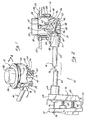
- Figures 2 and 3 depict a mechanical remote control system, generally designated by the numeral 10, for use with a conventional positioner in a recliner seat.
- the system includes a remote control 12 connected to an actuator 16 by a Bowden type control cable 14.
- the system 10 is installed in a typical airliner reclinable passenger seat with a conventional positioner device connected between the adjustable back-rest and a stationary bottom of the seat, such that the actuator 16 is mounted for controlling the positioner and the remote control 12 is mounted to an armrest of the recliner seat.
- the push-button remote control 12 is mounted in a hole 18 of an armrest wall 22.
- the wall 22 has an exterior side accessible to a chair occupant and an interior side.
- the control 12 has a cylindrical sleeve 24 with a radial flange 26 at its upper end and a radial groove 28 near an open bottom.
- the sleeve 24 is inserted into the mounting hole from the exterior of the arm rest to bring the flange 26 against the exterior side of armrest wall 22.
- a frame 20 fits onto the bottom of the sleeve 24 within the armrest.
- the frame 20 is integrally formed with a pair of diametrically opposed resilient retaining arms 32, seen in Figures 1 and 4.
- Each arm 32 has a detent 34 which projects radially inwardly and engages into the groove 28 to retain the frame 20 to the sleeve.
- a rim of the armrest wall 22 surrounding the mounting hole 18 is captive in an interference fit between the upper end of the frame 20 and the flange 26 to secure the control 12 in place.
- a spring washer 23 compressed between flange 26 and the armrest wall 22 eliminates loose play in the assembly.
- the control 12 can be disassembled and removed from the hole 18 by pressing radially inwardly onto the lower ends 25 of the two retaining arms to retract the detents 34 from the groove 28, allowing the frame 20 to separate axially from the sleeve 24.
- a plunger 35 is free to move up and down through an actuating stroke within a collar 36 defined in the frame 20.
- a push-button 30 is fixed to the upper end of the plunger and slides within the sleeve 24.
- a lever 40 is generally L-shaped, and is pivoted at 44 near the top of its vertical arm 46 to the frame 20 at a location radially outer to the plunger 35.
- the horizontal arm 48 of the lever extends radially inwardly towards the plunger 35 and terminates in a free end 50.
- the horizontal arm 48 of the lever is bifurcated by a vertical lever slot 56 into two legs 54, shown in Fig. 1.
- Each leg 54 of the lever has an upper camming edge 42.
- the two camming edges 42 are concavely curved in the vertical plane and are mutually parallel on either side of slot 56.
- the plunger 35 has a lower end 38 which is also bifurcated in a vertical plane, as shown in Figure 4, to define two parallel prongs 58 separated by a vertical slot 60.
- the lower end of each prong 58 is rounded and is in camming engagement with a corresponding camming edge 42 of the lever 40.
- the vertical slot 60 of the plunger and the vertical slot 56 of the lever are open to each other along the zone of camming contact between the lever and the plunger. Further, slots 56 and 60 lie in a common vertical plane which also contains the actuating stroke axis of the plunger 35.
- the control cable 14 has an outer sleeve 62 with an end fitting 64 which fits in a receptacle 27 integral to the frame 20, and is secured to the frame 20 by a split ring 29.
- the opposite end 66 of sleeve 62 is secured to a stationary jaw 68 of the actuator 16.
- the actuator has a movable jaw 70 connected to the stationary jaw 68 by hinge 72.
- the two jaws 68, 70 and hinge 72 are all molded as a unitary component of thermoplastic material.
- the fixed jaw 68 is mounted to the housing of a linear hydraulic positioner (not shown in the drawings) which may be of a conventional type commonly used in recliner seats. For example, one such positioner is described in U.S. Patent 5,211,379.
- a control wire 76 is longitudinally slidable within the cable sleeve 62.
- an exposed portion 86 of the wire 76 extends from the sleeve end 88 through the lever slot 56 and is engaged at 52 to the lower end of the vertical arm 46 of the lever 40.
- the exposed wire portion 86 is transverse to the longitudinal axis of the actuating stroke axis of the plunger 35, and is contained in the same vertical plane as the stroke axis.
- the opposite end 78 of the control wire is attached to the actuator 16 near the free end of the movable jaw 70.
- a spring 82 biases apart the actuator jaws 68, 70 to a normally open condition, thereby also pulling the control wire 76 and lever 40 of remote control 12 to a normal condition also shown in Figure 2.
- An actuating pin 80 threaded into the movable jaw 70 near the hinge 72 for mechanical advantage, is aligned with a through hole 84 in the fixed jaw.
- the camming end 38 of plunger 35 is positioned above the exposed wire portion 86, as seen in Figure 2.
- the push button 30 is depressed, driving the plunger 35 through its down-stroke to the fully depressed position of Figure 3, the lower end 38 of the plunger crosses the exposed wire portion 86 to a position where the plunger end 38 is positioned well below the exposed wire portion 86.
- the free end 50 of the lever 40 in following the down stroke of the plunger, moves across the exposed wire portion 86.
- the slot 60 of the plunger is aligned with the slot 56 of the lever in a vertical plane so that both the lever and the plunger are unimpeded in their movement through the actuating stroke by the exposed wire portion 86.
- the exposed wire portion 86 normally extends through the slot 56 of the lever and is admitted into the end slot 60 of the plunger during the lowermost portion of the down stroke.
- the bifurcated lever 35 and bifurcated plunger 40 both straddle the exposed wire portion 86 so that the depth of the down stroke is not limited or impeded by the transverse exposed wire portion 86. This is an important consideration because it allows the end fitting 64 of the control cable, from which extends the exposed wire portion 86, to be mounted to the frame 20 at a location above the lowermost position of the plunger end 38 during its actuation stroke.
- control assembly 12 below the supporting wall 22 is substantially lesser than in comparable prior art push-button controls. This, in turn, allows the control assembly of this invention to be used in seating applications demanding a more compact, lower profile control unit.
Landscapes
- Engineering & Computer Science (AREA)
- Aviation & Aerospace Engineering (AREA)
- Transportation (AREA)
- Mechanical Engineering (AREA)
- Chairs For Special Purposes, Such As Reclining Chairs (AREA)
- Flexible Shafts (AREA)
Claims (12)
- Eine Druckknopfbetätiger-Anordnung (16) für eine Kabelfernsteuerung (14) des Bowden-Typs, umfassend:einen Rahmen (20), einen Hebel (40), der an dem Rahmen angelenkt ist, einen Kolben (35), der in dem Rahmen (20) durch einen Betätigungshub zum Verschwenken des Hebels (14) von einer normalen Position zu einer niedergedrückten Position hinund her beweglich ist, eine Kabelhülse (62) mit einem an dem Rahmen (20) transversal zu dem Betätigungshub angebrachten Hülsenende (88), einen Steuerungsdraht (76) in der Hülse (62), wobei der Draht einen freiliegenden Teil (86) besitzt, der sich von dem Hülsenende (88) erstreckt und an dem Hebel (40) zur gleitenden Bewegung durch die Hülse (62) als Antwort auf das Drehen des Hebels (40) gleitend sich bewegt, und Einrichtungen (82) zur Rückführung des Hebels (40) zu der normalen Position, dadurch gekennzeichnet, daß der Kolben (35) so angeordnet und konfiguriert ist, daß er sich quer zu dem freiliegenden Teil (86) des Drahtes (76) während des Hubes bewegt, so daß das Hülsenende (88) an dem Rahmen (20) an einer Stelle montiert ist, die oberhalb des tiefsten Punktes des Betätigungshubes liegt, um dadurch eine kompaktere Betätigungsanordnung zu erhalten.
- Die Betätigungsanordnung nach Anspruch 1, wobei Teile des Hebels während des Drehens sich quer zu dem freiliegenden Teil bewegen.
- Die Betätigungsanordnung nach Anspruch 1, wobei der Kolben ein unteres Ende besitzt, welches gegen den Hebel wirkt, wobei das untere Ende sich während der Hubbewegung quer zu dem freiliegenden Teil bewegt.
- Die Betätigungsanordnung nach Anspruch 1, wobei der Kolben ein Ende in wirksamer Eingriffnahme mit dem Hebel aufweist, und das Ende so geformt und konfiguriert ist, um den freiliegenden Teil des Drahtes während dieser Hubbewegung aufzunehmen.
- Die Betätigungsanordnung nach Anspruch 4, wobei das Kolbenende geschlitzt ist, um den freiliegenden Teil des Drahtes während der Hubbewegung aufzunehmen.
- Die Betätigungsanordnung nach Anspruch 4 oder 5, wobei das Kolbenende sich in nockenartiger Eingriffnahme mit dem Hebel befindet.
- Die Betätigungsanordnung nach einem der vorangehenden Ansprüche, wobei die Einrichtungen zum Zurückführen eine Federeinrichtung umfassen, die den freiliegenden Teil zu einer normalerweise zurückgezogenen Position in der Kabelhülse entsprechend der normalen Position des Hebels zurückdrängt
- Die Betätigungsanordnung nach Anspruch 1, wobei der Hebel teilweise durch einen Hebelschlitz in zwei Nockenkanten geteilt ist, wobei das untere Ende des Kolbens durch einen Endschlitz in zwei Zinken aufgeteilt ist, wobei jeder Zinken sich in Nockeneingriff mit einer der entsprechenden Nockenkanten befindet, wobei der freiliegende Teil des Drahtes während eines Teils des Betätigungshubes in dem Endschlitz des Kolbens aufgenommen ist.
- Die Betätigungsanordnung nach Anspruch 8, wobei der freiliegende Teil des Drahtes sich normalweise durch den Hebelschlitz erstreckt.
- Die Betätigungsanordnung nach Anspruch 1, wobei der Hebel seitlich zu dem Hülsenende eine Kante aufweist, wobei der Kolben ein unteres Ende und der Hebel eine Nockenkontaktzone zwischen dem Hülsenende und der seitlichen Kante aufweist, wobei der Steuerdraht sich zu einem Drahtende erstreckt und an dem Hebel an der seitlichen Kante befestigt ist, wobei das untere Ende in Nockenkontakt mit der Nockenkontaktzone während des Betätigungshubes zum Drehen des Hebels von der normalen Position zu der niedrigeren Position steht, um den Draht durch die Hülse zu verschieben, wobei die Nockenkontaktzone während des Betätigungshubes quer zu dem freiliegenden Drahtteil verschoben wird.
- Die Betätigungsanordnung nach Anspruch 10, wobei das untere Ende des Kolbens und die Nockenkontaktzone des Hebels gegabelt sind, um den freiliegenden Drahtteil durch einen Endschlitz des Hebels und in einen Endschlitz des Kolbens aufzunehmen.
- Die Betätigungsanordnung nach Anspruch 1, wobei das untere Ende des Kolbens und der Hebel sich in Nockeneingriff zum Drehen des Hebels befinden, wobei das untere Ende in einer gemeinsamen Ebene geschlitzt ist, die den Betätigungshub enthält, um zwei parallele Zinken zu definieren, wobei der freiliegende Drahtteil während zumindest eines Teils der Betätigungsbewegung sich durch die Zinken erstreckt.
Applications Claiming Priority (2)
| Application Number | Priority Date | Filing Date | Title |
|---|---|---|---|
| US08/621,260 US5706705A (en) | 1996-03-21 | 1996-03-21 | Low profile push-button mechanical remote control |
| US621260 | 1996-03-21 |
Publications (2)
| Publication Number | Publication Date |
|---|---|
| EP0796576A1 EP0796576A1 (de) | 1997-09-24 |
| EP0796576B1 true EP0796576B1 (de) | 2002-06-05 |
Family
ID=24489433
Family Applications (1)
| Application Number | Title | Priority Date | Filing Date |
|---|---|---|---|
| EP97301856A Expired - Lifetime EP0796576B1 (de) | 1996-03-21 | 1997-03-19 | Mechanische Fernbedienungsanordnung mit Drucktastenschalter mit niedrigem Profil |
Country Status (4)
| Country | Link |
|---|---|
| US (1) | US5706705A (de) |
| EP (1) | EP0796576B1 (de) |
| JP (1) | JP3091710B2 (de) |
| DE (1) | DE69712951T2 (de) |
Families Citing this family (11)
| Publication number | Priority date | Publication date | Assignee | Title |
|---|---|---|---|---|
| DE19947002B4 (de) * | 1999-09-30 | 2008-05-29 | Fico Cables, Lda. | Verriegelungsmechanismus |
| US6223622B1 (en) | 2000-01-21 | 2001-05-01 | L&P Property Management Company | Push button cable actuator |
| US6315361B1 (en) | 2000-04-24 | 2001-11-13 | Porter Engineered Systems. | Seat adjustment and dumping system with memory |
| US6513875B1 (en) | 2000-11-03 | 2003-02-04 | Porter Engineered Systems | Fold-flat reclining mechanism for a vehicle seat |
| US6706984B1 (en) | 2002-11-20 | 2004-03-16 | S. Chase Turner | Device for remote activation of control box buttons |
| US7207522B2 (en) * | 2003-08-15 | 2007-04-24 | Apical Industries, Inc. | Safety device trigger for activating a safety device |
| JP5123714B2 (ja) * | 2008-04-07 | 2013-01-23 | 株式会社松永製作所 | プッシュボタンタイプリクライニング車椅子 |
| DE102010030967B4 (de) * | 2010-07-06 | 2012-10-25 | Lear Corp. | Sitzanordnung mit Druckknopfanordnung |
| US10173778B2 (en) * | 2016-05-17 | 2019-01-08 | Itt Manufacturing Enterprises Llc | Button assembly for seat position control |
| US12276367B2 (en) * | 2022-12-15 | 2025-04-15 | Itt Manufacturing Enterprises Llc | Flexible conduit for control cable having flame retardant outer sleeve |
| DE102024127007A1 (de) * | 2024-09-19 | 2026-03-19 | Recaro Aircraft Seating Gmbh & Co. Kg | Flugzeugsitzbetätigungsvorrichtung |
Family Cites Families (11)
| Publication number | Priority date | Publication date | Assignee | Title |
|---|---|---|---|---|
| US4354398A (en) * | 1978-09-05 | 1982-10-19 | P. L. Porter Co. | Control mechanism for hydraulic locking device |
| DE3039584C2 (de) * | 1980-10-20 | 1985-03-21 | Klöckner-Humboldt-Deutz AG Zweigniederlassung Fahr, 7702 Gottmadingen | Regulierhebel, insbesondere zur Vorwahl der Fahrgeschwindigkeit an selbstfahrenden landwirtschaftlichen Maschinen |
| DE3464565D1 (en) * | 1983-02-11 | 1987-08-13 | Aisin Seiki | Stick type vehicle hand brake |
| US4856762A (en) * | 1986-07-08 | 1989-08-15 | Selzer Guenther | Fire retardant gas spring assembly for a passenger seat control |
| JP2664155B2 (ja) * | 1987-07-05 | 1997-10-15 | 日産自動車株式会社 | オートマチックトランスミッションのコントロールデバイス |
| US4774850A (en) * | 1987-08-24 | 1988-10-04 | Regal Plastics Company | Gear shifter cartridge |
| US5107720A (en) * | 1991-07-24 | 1992-04-28 | Plastic Industries, Inc. | Device for actuating a remotely positioned latch |
| US5179870A (en) * | 1991-12-16 | 1993-01-19 | Chrysler Corporation | Shift control lever assembly |
| FR2698839B1 (fr) * | 1992-12-03 | 1995-03-03 | Rockwell Abs France | Frein de parc pour véhicule automobile à faible effort de serrage. |
| US5497676A (en) * | 1994-04-04 | 1996-03-12 | Wescon Products Company | Actuator control assembly for motion furniture |
| US5595420A (en) * | 1994-09-08 | 1997-01-21 | Rogers; W. Clark | Dual-operated mechanism for remote latch actuation |
-
1996
- 1996-03-21 US US08/621,260 patent/US5706705A/en not_active Expired - Fee Related
-
1997
- 1997-03-19 DE DE69712951T patent/DE69712951T2/de not_active Expired - Fee Related
- 1997-03-19 EP EP97301856A patent/EP0796576B1/de not_active Expired - Lifetime
- 1997-03-21 JP JP09085519A patent/JP3091710B2/ja not_active Expired - Fee Related
Also Published As
| Publication number | Publication date |
|---|---|
| DE69712951T2 (de) | 2003-04-03 |
| JPH1028623A (ja) | 1998-02-03 |
| US5706705A (en) | 1998-01-13 |
| DE69712951D1 (de) | 2002-07-11 |
| JP3091710B2 (ja) | 2000-09-25 |
| EP0796576A1 (de) | 1997-09-24 |
Similar Documents
| Publication | Publication Date | Title |
|---|---|---|
| EP0796576B1 (de) | Mechanische Fernbedienungsanordnung mit Drucktastenschalter mit niedrigem Profil | |
| US8025338B2 (en) | Adjustable head restraint system for an automotive vehicle seat | |
| US20090026825A1 (en) | Seat | |
| US5711579A (en) | Locking arrangement for a head restraint | |
| CN101137306B (zh) | 多用途座椅调整机构 | |
| US4779925A (en) | Height-adjustable swivel chair equipped with gas-pressure spring, especially office chair or office armchair | |
| CN101325898B (zh) | 具有至少一个枢转手柄的烹调容器 | |
| JPH02111310A (ja) | シートの背もたれの傾き調節装置 | |
| WO1999035939A1 (en) | Multi-position chair control mechanism for synchronously adjusting the seat and backrest of a chair | |
| US5427434A (en) | Chair tilt and height adjustment mechanism | |
| EP1454567A1 (de) | Stuhl mit einem Schwenksitz | |
| EP0286262A2 (de) | Fernbedienung | |
| WO2010080219A2 (en) | Adjustable headrest assembly for furniture member | |
| JPH06147246A (ja) | ロック可能なガスばねのための解除装置 | |
| EP0970846A1 (de) | Kopfstütze für Kraftfahrzeug | |
| GB2252725A (en) | Locking adjustment for furniture | |
| CA2366473A1 (en) | Downwardly pivoting armrest | |
| JP4027186B2 (ja) | ピストンシリンダユニット | |
| KR860001705Y1 (ko) | 리크라이너 | |
| KR101466956B1 (ko) | 의자의 암레스트 높낮이 조절 장치 | |
| US7419219B2 (en) | Adjustable arm assembly for a chair | |
| JP2900191B2 (ja) | 椅 子 | |
| EP3096650B1 (de) | Mechanismus zur betätigung einer einstellvorrichtung eines bürostuhls und zugehörige einstellungsvorrichtung | |
| US20260116543A1 (en) | Armrest provided with a rotational adjustment system | |
| CN220212474U (zh) | 一种调节椅背深度的线控安装结构 |
Legal Events
| Date | Code | Title | Description |
|---|---|---|---|
| PUAI | Public reference made under article 153(3) epc to a published international application that has entered the european phase |
Free format text: ORIGINAL CODE: 0009012 |
|
| AK | Designated contracting states |
Kind code of ref document: A1 Designated state(s): DE FR GB IT |
|
| 17P | Request for examination filed |
Effective date: 19971215 |
|
| 17Q | First examination report despatched |
Effective date: 20000710 |
|
| RTI1 | Title (correction) |
Free format text: LOW PROFILE PUSH-BUTTON MECHANICAL REMOTE CONTROL |
|
| RTI1 | Title (correction) |
Free format text: LOW PROFILE PUSH-BUTTON MECHANICAL REMOTE CONTROL |
|
| GRAG | Despatch of communication of intention to grant |
Free format text: ORIGINAL CODE: EPIDOS AGRA |
|
| GRAG | Despatch of communication of intention to grant |
Free format text: ORIGINAL CODE: EPIDOS AGRA |
|
| GRAH | Despatch of communication of intention to grant a patent |
Free format text: ORIGINAL CODE: EPIDOS IGRA |
|
| GRAH | Despatch of communication of intention to grant a patent |
Free format text: ORIGINAL CODE: EPIDOS IGRA |
|
| GRAA | (expected) grant |
Free format text: ORIGINAL CODE: 0009210 |
|
| AK | Designated contracting states |
Kind code of ref document: B1 Designated state(s): DE FR GB IT |
|
| REG | Reference to a national code |
Ref country code: GB Ref legal event code: FG4D |
|
| REF | Corresponds to: |
Ref document number: 69712951 Country of ref document: DE Date of ref document: 20020711 |
|
| ET | Fr: translation filed | ||
| PLBE | No opposition filed within time limit |
Free format text: ORIGINAL CODE: 0009261 |
|
| STAA | Information on the status of an ep patent application or granted ep patent |
Free format text: STATUS: NO OPPOSITION FILED WITHIN TIME LIMIT |
|
| 26N | No opposition filed |
Effective date: 20030306 |
|
| PGFP | Annual fee paid to national office [announced via postgrant information from national office to epo] |
Ref country code: GB Payment date: 20070327 Year of fee payment: 11 |
|
| PGFP | Annual fee paid to national office [announced via postgrant information from national office to epo] |
Ref country code: DE Payment date: 20070430 Year of fee payment: 11 |
|
| PGFP | Annual fee paid to national office [announced via postgrant information from national office to epo] |
Ref country code: IT Payment date: 20070525 Year of fee payment: 11 |
|
| PGFP | Annual fee paid to national office [announced via postgrant information from national office to epo] |
Ref country code: FR Payment date: 20070319 Year of fee payment: 11 |
|
| GBPC | Gb: european patent ceased through non-payment of renewal fee |
Effective date: 20080319 |
|
| REG | Reference to a national code |
Ref country code: FR Ref legal event code: ST Effective date: 20081125 |
|
| PG25 | Lapsed in a contracting state [announced via postgrant information from national office to epo] |
Ref country code: DE Free format text: LAPSE BECAUSE OF NON-PAYMENT OF DUE FEES Effective date: 20081001 |
|
| PG25 | Lapsed in a contracting state [announced via postgrant information from national office to epo] |
Ref country code: FR Free format text: LAPSE BECAUSE OF NON-PAYMENT OF DUE FEES Effective date: 20080331 |
|
| PG25 | Lapsed in a contracting state [announced via postgrant information from national office to epo] |
Ref country code: GB Free format text: LAPSE BECAUSE OF NON-PAYMENT OF DUE FEES Effective date: 20080319 |
|
| PG25 | Lapsed in a contracting state [announced via postgrant information from national office to epo] |
Ref country code: IT Free format text: LAPSE BECAUSE OF NON-PAYMENT OF DUE FEES Effective date: 20080319 |