EP0796580A1 - Noyau à ressorts pour coussin - Google Patents
Noyau à ressorts pour coussin Download PDFInfo
- Publication number
- EP0796580A1 EP0796580A1 EP97100304A EP97100304A EP0796580A1 EP 0796580 A1 EP0796580 A1 EP 0796580A1 EP 97100304 A EP97100304 A EP 97100304A EP 97100304 A EP97100304 A EP 97100304A EP 0796580 A1 EP0796580 A1 EP 0796580A1
- Authority
- EP
- European Patent Office
- Prior art keywords
- spring
- foam body
- spring core
- springs
- elevations
- Prior art date
- Legal status (The legal status is an assumption and is not a legal conclusion. Google has not performed a legal analysis and makes no representation as to the accuracy of the status listed.)
- Granted
Links
Images
Classifications
-
- A—HUMAN NECESSITIES
- A47—FURNITURE; DOMESTIC ARTICLES OR APPLIANCES; COFFEE MILLS; SPICE MILLS; SUCTION CLEANERS IN GENERAL
- A47C—CHAIRS; SOFAS; BEDS
- A47C27/00—Spring, stuffed or fluid mattresses or cushions specially adapted for chairs, beds or sofas
- A47C27/04—Spring, stuffed or fluid mattresses or cushions specially adapted for chairs, beds or sofas with spring inlays
- A47C27/05—Spring, stuffed or fluid mattresses or cushions specially adapted for chairs, beds or sofas with spring inlays with padding material, e.g. foamed material, in top, bottom, or side layers
- A47C27/053—Spring, stuffed or fluid mattresses or cushions specially adapted for chairs, beds or sofas with spring inlays with padding material, e.g. foamed material, in top, bottom, or side layers with only one layer of foamed material
-
- A—HUMAN NECESSITIES
- A47—FURNITURE; DOMESTIC ARTICLES OR APPLIANCES; COFFEE MILLS; SPICE MILLS; SUCTION CLEANERS IN GENERAL
- A47C—CHAIRS; SOFAS; BEDS
- A47C27/00—Spring, stuffed or fluid mattresses or cushions specially adapted for chairs, beds or sofas
- A47C27/14—Spring, stuffed or fluid mattresses or cushions specially adapted for chairs, beds or sofas with foamed material inlays
- A47C27/20—Spring, stuffed or fluid mattresses or cushions specially adapted for chairs, beds or sofas with foamed material inlays with springs moulded in, or situated in openings in foamed material
Definitions
- the present invention relates to a spring core according to claim 1 and in particular to a multi-layer spring core with a central foam body, in which a plurality of spring elements are used, and a cushion element with such a spring core.
- Such spring cores are used in the furniture industry and are used in particular as a core element in mattresses or upholstered furniture. These core pieces are decisive for the lifespan and hardness of the pieces of furniture and are usually provided with a cushion layer that determines the lying or sitting comfort before they are covered with a firm drill.
- synthetic foams are increasingly being used in addition to foam rubber or foamed latex for reasons of cost.
- the compression hardness and thus the spring force of these foams noticeably diminish after a short time, making them unsuitable for use in heavily used furniture.
- Improved spring cores therefore consist of a combination of foam and spring elements.
- spring cores are used today in railroad or airplane seats, in which metallic springs are directly foamed in a foam body. In this way, the service life can be extended compared to pure foam innersprings; However, comfortable and inexpensive seating or reclining furniture cannot be manufactured with it.
- the direct foaming in of the spring elements requires complex machine tools and increases the cost of manufacture, especially in the case of smaller production quantities.
- it has proven essential for the comfort of reclining and seating furniture that they have good point elasticity, that is to say they have a pronounced local spring force.
- foaming the spring elements however, these are coupled to one another and can therefore no longer be a local load profile independently of one another consequences.
- the foam in the area of the metallic spring elements suffers from this type of composite spring cores and these composite spring cores often have to be replaced when used heavily.
- a combination spring core with a central foam body is to be created, in the production of which no systematically generated waste pieces are produced and with which spring core silent and freely dimensionable cushion elements can be produced.
- the central foam body is profiled on both sides in a special way, i.e. the elevations and depressions of the respective profile have a complementary geometric shape.
- Spring elements preferably metallic spiral springs, are used at those points where depressions lie opposite one another.
- This special shape of the central foam body and the spiral springs used also ensures that the spring elements are installed in the correct position within this foam body, since these spring elements are shaped and dimensioned such that their ends rest on the elevations of the foam body profile.
- the spiral springs are preloaded and can be clamped onto the elevations of the foam body profile.
- the construction according to the invention leads to the fact that when the cover layers, respectively.
- Upholstery carrier also called cover layers below, on the foam body, the ends of the spiral springs between these cover layers and the foam body are held.
- Spiral springs used and fixed in this way lie next to each other precisely and without contact even after intensive and prolonged use and cannot rub against the cover layers. Your vibration behavior can by the Foam body and the top layers are damped in the desired manner.
- the double-conical shape of the spiral springs on the one hand and the foam part in the middle prevent the individual spiral flights of the spiral springs from resting on top of one another under extreme loads or low installation heights.
- the elevations of the foam body profile are formed on both sides as parallel ribs.
- These ribs have a complementary geometric shape to their gaps, whereby low-waste production can be realized and the production costs can be reduced.
- these ribs have a stiffening effect in their longitudinal direction and at the same time allow the spring core to be bent in the transverse direction without great effort, as is desired in the case of beds with adjustable head and / or foot ends. When bending, the cushion layer can escape into the spaces between the ribbed foam body and thus increases the flexibility of the entire cushion element transverse to the direction of the ribs.
- the individual fixation of the spring elements in the spaces between these ribs also creates optimal point elasticity and the spring core can be assembled in a simple manner, i.e. cut into desired sizes.
- the physical properties of the foam used for the foam body or the cover layers are selected in a desired manner by a person skilled in the art and the spring strengths or.
- Spring shapes can be adapted to the desired requirements.
- individual springs can be combined into spring groups in order to be able to correspond to an individual load profile or additional cushion or spring layers can be provided.
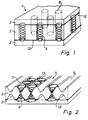
- the spring core 1 of known type shown in FIG. 1 has a central foam body 3 which is provided with cover layers 2 on both sides.
- An elastic adhesive layer 12 ensures the connection between the cover layers 2 and the foam body 3.
- These cover layers 2 can consist of a simple foam layer or additionally comprise a nonwoven layer.
- the foam body 3 has cylindrical recesses 6, in which spring elements 4 are inserted. When this spring core is subjected to a local load, the individual springs are coupled to one another by the solid foam body 3 and by the relatively stiff fiber fleece, ie they cannot really be point-elastic Act.
- Foams are not only synthetic products but also natural foam rubber or foamed latex.
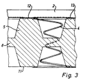
- Figure 2 shows a central foam body 3, which is provided on both sides with a rib-shaped profile, the elevations 5 and depressions 7 have a complementary geometric shape.
- the cross section of the rib-shaped profile is trapezoidal and has a wider base towards the central part. It goes without saying that this trapezoidal cross section can also be designed such that the wider base lies on the side of the cover layers 2.
- the spring elements 4 are mounted in the respective recesses 7, i.e. are not coupled together by the foam body 3 and ensure good point elasticity.
- the individual spring elements 4 are adapted to the flank profile of the profile and have a biconical shape in the embodiment shown. In order to ensure the exact positioning of the springs within the spring core, the winding ends of the individual spring elements 4 protrude above the elevations 5 and rest on the end faces 11 of these elevations.
- the respective cover layers 2 are glued to the end faces 11 of the elevations 5 of this profile. Through this gluing, the spring ends are held in their position and cannot slide out of their position and touch each other, even in the event of extreme compressions or deflections of the entire spring core. In addition, this fixation prevents the spring elements from rubbing against the cover layers and damaging them after prolonged use.
- the ribs running parallel to one another on both sides of the foam body 3 lead on the one hand to a stiffening of the entire spring core in the direction of the ribs 5 and at the same time to a greater flexibility transversely to this direction.
- the complementary is essential to the invention Geometric shape of the elevations 5 and depressions 7 of the profile, since there is no undesired cutting waste during the production of this central foam body 3. This special geometric design also leads to cross ventilation, which facilitates the noiseless escape of air under extreme loads.
- Figure 3 shows a section of the preferred embodiment.
- This has a central foam body 3 with ribs 5, the trapezoidal cross section of which tapers towards the top layer 2.
- a spiral spring 4 is used, the uppermost end of the winding 13 rests on the end face 11 of the profile elevation 5.
- These spiral springs 4 are preferably preloaded such that they act against the spring force of the foam body ribs 5. It is thereby achieved that the springing behavior inherent in the spring elements is dampened by the elasticity of the foam.
- the hardness of the springs can be chosen according to requirements and is essentially determined by the thickness of the spring wire. In the preferred embodiments, springs with a wire thickness of 1.4 to 2.6 mm are used.
- the maximum diameter of these springs is 60mm, but can of course be adapted to the geometry of the foam body.
- Plastic foams of 20-70 kg / m 3 are preferably used as the foam body.
- the profiled foam body 3 has, for example, a total height of 10 cm, the central web 8 of which has a thickness of 15 mm.
- the height of the individual springs 4 is adapted to this overall height of the foam body and varies in the preferred embodiments between 6 cm and 14 cm.
- the adhesive layer 12 creates a connection between the end faces 11 of the elevations 5 and the cover layer 2, such that the winding end 13 is held in place.
- these cover layers 2 consist of foam with a thickness of approximately 25 mm, so that the entire innerspring can be reduced to a height of 11cm.
- a significant advantage in the combination of foam with metallic springs is the fact that the elasticity of the plastic foam, which usually diminishes in the longer term, can be maintained through the dimensional stability of the spiral springs.
- spring elements can be selected and used in accordance with the application.
- biconical, cylindrical or barrel-shaped spring elements can be used. It is also in the technical ability to combine individual springs into groups in order to adapt the spring-elastic properties to the desired load profiles. It goes without saying that the person skilled in the art would also consider rubber springs or similar elastic elements instead of the spiral springs.
- the foam body can be cut from one piece or constructed from several different layers. The recesses of the ribbed foam body can be slotted in a suitable manner for easier assembly of the spring elements. The flanks of the individual ribs can be adapted to the shape of the spring. It is also within the skill in the art to choose an adhesive with the desired elasticity for the adhesive layer 12.
Landscapes
- Springs (AREA)
- Mattresses And Other Support Structures For Chairs And Beds (AREA)
- Chair Legs, Seat Parts, And Backrests (AREA)
- Prostheses (AREA)
Applications Claiming Priority (3)
| Application Number | Priority Date | Filing Date | Title |
|---|---|---|---|
| CH27996 | 1996-02-02 | ||
| CH279/96 | 1996-02-02 | ||
| CH27996 | 1996-02-02 |
Publications (2)
| Publication Number | Publication Date |
|---|---|
| EP0796580A1 true EP0796580A1 (fr) | 1997-09-24 |
| EP0796580B1 EP0796580B1 (fr) | 2001-03-14 |
Family
ID=4183384
Family Applications (1)
| Application Number | Title | Priority Date | Filing Date |
|---|---|---|---|
| EP97100304A Expired - Lifetime EP0796580B1 (fr) | 1996-02-02 | 1997-01-10 | Noyau à ressorts pour coussin |
Country Status (3)
| Country | Link |
|---|---|
| EP (1) | EP0796580B1 (fr) |
| AT (1) | ATE199633T1 (fr) |
| DE (1) | DE59703121D1 (fr) |
Cited By (2)
| Publication number | Priority date | Publication date | Assignee | Title |
|---|---|---|---|---|
| DE29719171U1 (de) * | 1997-10-29 | 1999-03-04 | Polus, Michael, Dr., 90489 Nürnberg | Matratze in Vollmaterial-Ausbildung |
| EP2296509A4 (fr) * | 2008-01-18 | 2011-08-17 | Sealy Technology Llc | Inserts amortisseurs pour ressorts internes |
Citations (3)
| Publication number | Priority date | Publication date | Assignee | Title |
|---|---|---|---|---|
| FR1110462A (fr) * | 1954-09-03 | 1956-02-13 | Matelas ou coussin perfectionné | |
| FR1593548A (fr) * | 1968-06-13 | 1970-06-01 | ||
| DE2820282A1 (de) * | 1978-05-10 | 1979-11-15 | Recticel Deutsch Kunststoffe | Verfahren zum herstellen von polstern aus geschaeumtem, vorzugsweise luftdurchlaessigem werkstoff, z.b. aus geschaeumtem polyurethan, und nach diesem verfahren hergestelltes polster |
-
1997
- 1997-01-10 AT AT97100304T patent/ATE199633T1/de not_active IP Right Cessation
- 1997-01-10 EP EP97100304A patent/EP0796580B1/fr not_active Expired - Lifetime
- 1997-01-10 DE DE59703121T patent/DE59703121D1/de not_active Expired - Fee Related
Patent Citations (3)
| Publication number | Priority date | Publication date | Assignee | Title |
|---|---|---|---|---|
| FR1110462A (fr) * | 1954-09-03 | 1956-02-13 | Matelas ou coussin perfectionné | |
| FR1593548A (fr) * | 1968-06-13 | 1970-06-01 | ||
| DE2820282A1 (de) * | 1978-05-10 | 1979-11-15 | Recticel Deutsch Kunststoffe | Verfahren zum herstellen von polstern aus geschaeumtem, vorzugsweise luftdurchlaessigem werkstoff, z.b. aus geschaeumtem polyurethan, und nach diesem verfahren hergestelltes polster |
Cited By (2)
| Publication number | Priority date | Publication date | Assignee | Title |
|---|---|---|---|---|
| DE29719171U1 (de) * | 1997-10-29 | 1999-03-04 | Polus, Michael, Dr., 90489 Nürnberg | Matratze in Vollmaterial-Ausbildung |
| EP2296509A4 (fr) * | 2008-01-18 | 2011-08-17 | Sealy Technology Llc | Inserts amortisseurs pour ressorts internes |
Also Published As
| Publication number | Publication date |
|---|---|
| ATE199633T1 (de) | 2001-03-15 |
| EP0796580B1 (fr) | 2001-03-14 |
| DE59703121D1 (de) | 2001-04-19 |
Similar Documents
| Publication | Publication Date | Title |
|---|---|---|
| EP1068094B1 (fr) | Coussin pour siège d'automobile | |
| EP2139366B1 (fr) | Élément d'appui pour support de rembourrage de surfaces d'assise et de surfaces de couchage | |
| EP3393303B1 (fr) | Partie centrale en mousse pour un rembourrage d'une partie d'assise ou d'une partie de couchage ou d'un dossier d'un meuble rembourré ou d'un siège de véhicule | |
| DE102013202688B4 (de) | Sitzkissen für einen Fahrzeugsitz | |
| EP1362534B1 (fr) | Support par tapis de ressorts | |
| EP2123197B1 (fr) | Noyau de ressort doté d'un renforcement de bord | |
| WO2005048781A2 (fr) | Element de support | |
| DE202010015380U1 (de) | Federelement | |
| EP1825783B1 (fr) | Ressort pour nappe de support et nappe de support dans des constructions de siège | |
| EP1952727A2 (fr) | Rembourrage en mousse | |
| EP2225973B1 (fr) | Ressort de matelas | |
| EP0632702B1 (fr) | Element rembourre | |
| DE102008055549B4 (de) | Federelement aus Schaumstoff | |
| EP1050251B1 (fr) | Sommier à lattes | |
| EP2110056A1 (fr) | Agencement composite | |
| DE1943832A1 (de) | Polsterauflage und Verfahren zur Herstellung derselben | |
| DE2935438C2 (fr) | ||
| EP0796580B1 (fr) | Noyau à ressorts pour coussin | |
| EP0397978B1 (fr) | Latte pour sommier à lattes | |
| EP0839481B1 (fr) | Noyau interne de rembourrage en mousse et procédé de sa fabrication | |
| WO1995002977A1 (fr) | Matelas | |
| DE102010014664B4 (de) | Polsterelement, insbesondere eine Matratze | |
| EP3207830B1 (fr) | Matelas d'appoint | |
| EP0670128B1 (fr) | Sommier | |
| DE20113727U1 (de) | Matratze |
Legal Events
| Date | Code | Title | Description |
|---|---|---|---|
| PUAI | Public reference made under article 153(3) epc to a published international application that has entered the european phase |
Free format text: ORIGINAL CODE: 0009012 |
|
| AK | Designated contracting states |
Kind code of ref document: A1 Designated state(s): AT CH DE FR IT LI |
|
| 17P | Request for examination filed |
Effective date: 19980128 |
|
| 17Q | First examination report despatched |
Effective date: 19990622 |
|
| GRAG | Despatch of communication of intention to grant |
Free format text: ORIGINAL CODE: EPIDOS AGRA |
|
| GRAG | Despatch of communication of intention to grant |
Free format text: ORIGINAL CODE: EPIDOS AGRA |
|
| GRAH | Despatch of communication of intention to grant a patent |
Free format text: ORIGINAL CODE: EPIDOS IGRA |
|
| GRAH | Despatch of communication of intention to grant a patent |
Free format text: ORIGINAL CODE: EPIDOS IGRA |
|
| GRAA | (expected) grant |
Free format text: ORIGINAL CODE: 0009210 |
|
| AK | Designated contracting states |
Kind code of ref document: B1 Designated state(s): AT CH DE FR IT LI |
|
| REF | Corresponds to: |
Ref document number: 199633 Country of ref document: AT Date of ref document: 20010315 Kind code of ref document: T |
|
| REG | Reference to a national code |
Ref country code: CH Ref legal event code: EP |
|
| REF | Corresponds to: |
Ref document number: 59703121 Country of ref document: DE Date of ref document: 20010419 |
|
| REG | Reference to a national code |
Ref country code: CH Ref legal event code: NV Representative=s name: RITSCHER & SEIFERT |
|
| ET | Fr: translation filed | ||
| ITF | It: translation for a ep patent filed | ||
| PLBE | No opposition filed within time limit |
Free format text: ORIGINAL CODE: 0009261 |
|
| STAA | Information on the status of an ep patent application or granted ep patent |
Free format text: STATUS: NO OPPOSITION FILED WITHIN TIME LIMIT |
|
| 26N | No opposition filed | ||
| PGFP | Annual fee paid to national office [announced via postgrant information from national office to epo] |
Ref country code: FR Payment date: 20041230 Year of fee payment: 9 |
|
| PGFP | Annual fee paid to national office [announced via postgrant information from national office to epo] |
Ref country code: AT Payment date: 20050104 Year of fee payment: 9 |
|
| PGFP | Annual fee paid to national office [announced via postgrant information from national office to epo] |
Ref country code: DE Payment date: 20050113 Year of fee payment: 9 |
|
| PGFP | Annual fee paid to national office [announced via postgrant information from national office to epo] |
Ref country code: CH Payment date: 20050321 Year of fee payment: 9 |
|
| PG25 | Lapsed in a contracting state [announced via postgrant information from national office to epo] |
Ref country code: AT Free format text: LAPSE BECAUSE OF NON-PAYMENT OF DUE FEES Effective date: 20060110 |
|
| PG25 | Lapsed in a contracting state [announced via postgrant information from national office to epo] |
Ref country code: LI Free format text: LAPSE BECAUSE OF NON-PAYMENT OF DUE FEES Effective date: 20060131 Ref country code: FR Free format text: LAPSE BECAUSE OF NON-PAYMENT OF DUE FEES Effective date: 20060131 Ref country code: CH Free format text: LAPSE BECAUSE OF NON-PAYMENT OF DUE FEES Effective date: 20060131 |
|
| PGFP | Annual fee paid to national office [announced via postgrant information from national office to epo] |
Ref country code: IT Payment date: 20060131 Year of fee payment: 10 |
|
| PG25 | Lapsed in a contracting state [announced via postgrant information from national office to epo] |
Ref country code: DE Free format text: LAPSE BECAUSE OF NON-PAYMENT OF DUE FEES Effective date: 20060801 |
|
| REG | Reference to a national code |
Ref country code: CH Ref legal event code: PL |
|
| REG | Reference to a national code |
Ref country code: FR Ref legal event code: ST Effective date: 20060929 |
|
| PG25 | Lapsed in a contracting state [announced via postgrant information from national office to epo] |
Ref country code: IT Free format text: LAPSE BECAUSE OF NON-PAYMENT OF DUE FEES Effective date: 20070110 |