EP0796592A2 - Dispositif jetable à lancette - Google Patents
Dispositif jetable à lancette Download PDFInfo
- Publication number
- EP0796592A2 EP0796592A2 EP97104504A EP97104504A EP0796592A2 EP 0796592 A2 EP0796592 A2 EP 0796592A2 EP 97104504 A EP97104504 A EP 97104504A EP 97104504 A EP97104504 A EP 97104504A EP 0796592 A2 EP0796592 A2 EP 0796592A2
- Authority
- EP
- European Patent Office
- Prior art keywords
- housing
- button
- actuator
- lancet device
- spring mechanism
- Prior art date
- Legal status (The legal status is an assumption and is not a legal conclusion. Google has not performed a legal analysis and makes no representation as to the accuracy of the status listed.)
- Withdrawn
Links
Images




Classifications
-
- A—HUMAN NECESSITIES
- A61—MEDICAL OR VETERINARY SCIENCE; HYGIENE
- A61B—DIAGNOSIS; SURGERY; IDENTIFICATION
- A61B5/00—Measuring for diagnostic purposes; Identification of persons
- A61B5/15—Devices for taking samples of blood
- A61B5/151—Devices specially adapted for taking samples of capillary blood, e.g. by lancets, needles or blades
- A61B5/15142—Devices intended for single use, i.e. disposable
-
- A—HUMAN NECESSITIES
- A61—MEDICAL OR VETERINARY SCIENCE; HYGIENE
- A61B—DIAGNOSIS; SURGERY; IDENTIFICATION
- A61B5/00—Measuring for diagnostic purposes; Identification of persons
- A61B5/15—Devices for taking samples of blood
- A61B5/150007—Details
- A61B5/150015—Source of blood
- A61B5/150022—Source of blood for capillary blood or interstitial fluid
-
- A—HUMAN NECESSITIES
- A61—MEDICAL OR VETERINARY SCIENCE; HYGIENE
- A61B—DIAGNOSIS; SURGERY; IDENTIFICATION
- A61B5/00—Measuring for diagnostic purposes; Identification of persons
- A61B5/15—Devices for taking samples of blood
- A61B5/150007—Details
- A61B5/150374—Details of piercing elements or protective means for preventing accidental injuries by such piercing elements
- A61B5/150381—Design of piercing elements
- A61B5/150412—Pointed piercing elements, e.g. needles, lancets for piercing the skin
- A61B5/150435—Specific design of proximal end
-
- A—HUMAN NECESSITIES
- A61—MEDICAL OR VETERINARY SCIENCE; HYGIENE
- A61B—DIAGNOSIS; SURGERY; IDENTIFICATION
- A61B5/00—Measuring for diagnostic purposes; Identification of persons
- A61B5/15—Devices for taking samples of blood
- A61B5/150007—Details
- A61B5/150374—Details of piercing elements or protective means for preventing accidental injuries by such piercing elements
- A61B5/150381—Design of piercing elements
- A61B5/150473—Double-ended needles, e.g. used with pre-evacuated sampling tubes
- A61B5/150488—Details of construction of shaft
-
- A—HUMAN NECESSITIES
- A61—MEDICAL OR VETERINARY SCIENCE; HYGIENE
- A61B—DIAGNOSIS; SURGERY; IDENTIFICATION
- A61B5/00—Measuring for diagnostic purposes; Identification of persons
- A61B5/15—Devices for taking samples of blood
- A61B5/151—Devices specially adapted for taking samples of capillary blood, e.g. by lancets, needles or blades
- A61B5/15101—Details
- A61B5/15103—Piercing procedure
- A61B5/15107—Piercing being assisted by a triggering mechanism
- A61B5/15113—Manually triggered, i.e. the triggering requires a deliberate action by the user such as pressing a drive button
-
- A—HUMAN NECESSITIES
- A61—MEDICAL OR VETERINARY SCIENCE; HYGIENE
- A61B—DIAGNOSIS; SURGERY; IDENTIFICATION
- A61B5/00—Measuring for diagnostic purposes; Identification of persons
- A61B5/15—Devices for taking samples of blood
- A61B5/151—Devices specially adapted for taking samples of capillary blood, e.g. by lancets, needles or blades
- A61B5/15101—Details
- A61B5/15126—Means for controlling the lancing movement, e.g. 2D- or 3D-shaped elements, tooth-shaped elements or sliding guides
- A61B5/15128—Means for controlling the lancing movement, e.g. 2D- or 3D-shaped elements, tooth-shaped elements or sliding guides comprising 2D- or 3D-shaped elements, e.g. cams, curved guide rails or threads
-
- A—HUMAN NECESSITIES
- A61—MEDICAL OR VETERINARY SCIENCE; HYGIENE
- A61B—DIAGNOSIS; SURGERY; IDENTIFICATION
- A61B5/00—Measuring for diagnostic purposes; Identification of persons
- A61B5/15—Devices for taking samples of blood
- A61B5/151—Devices specially adapted for taking samples of capillary blood, e.g. by lancets, needles or blades
- A61B5/15142—Devices intended for single use, i.e. disposable
- A61B5/15144—Devices intended for single use, i.e. disposable comprising driving means, e.g. a spring, for retracting the piercing unit into the housing
-
- A—HUMAN NECESSITIES
- A61—MEDICAL OR VETERINARY SCIENCE; HYGIENE
- A61B—DIAGNOSIS; SURGERY; IDENTIFICATION
- A61B17/00—Surgical instruments, devices or methods
- A61B2017/0023—Surgical instruments, devices or methods disposable
Definitions
- the invention concerns a lancet device which is suitable for a single use only and which is effectively unusable after a single use.
- the device also includes indicators by which a user can readily visibly determine whether or not the device has been used yet.
- Sharp pointed or bladed lancets are frequently used to make a small penetration of a patient's skin to let a small volume of blood for diagnostic purposes.
- communicable diseases such as AIDS, hepatitis, etc.
- precautions are necessary to insure that once used, a lancet cannot be accidentally used again.
- the lancet tip be completely and securely shielded after use and disposal, to prevent accidental contact with sanitation workers or anyone else that might accidentally come into contact with the device.
- Spring-energized i.e., preloaded spring driven lancets of many types have been known and used as a replacement for needles for piercing the skin for blood samples.
- Some of these devices are designed as single use, disposable devices.
- the relative complexity of such devices has made them expensive to manufacture and, often, unreliable in use.
- the preloaded spring can often lead to misfiring of the lancet tip or skewing of the spring so as to make an unacceptable incision or an incision which imparts more pain to the patient than absolutely necessary.
- U.S. Patent No. 5,356,420 discloses a preloaded device in which a puncturing tip 7 is mounted on a piston 5 within a piston sleeve 1.
- a power spring 9 is preloaded within the sleeve and actuated by depression of a push-button 2.
- An additional spring 10 is provided to ensure that the puncturing tip 7 is retracted into the sleeve after use.
- U.S. Patent No. 4,889,117 discloses a disposable lancet (Figs. 7 and 8) in which a needle tip 48' is provided within a tube 50.
- a cap 44 is provided at one end to the tube 50.
- the tip 48' protrudes from the tube 50 and pierces the skin of the patient.
- a spring steel formed washer 60 is provided to ensure that the tip is retracted back within the tube 50 when the force is removed from the cap 44.
- An inwardly biased tang 62 prevents re-use of the lancet after the initial use.
- this type of device where a driving force implied to the cap is in the direction of the patient's skin, when the operator operates the device, the force applied for operation may apply an excessive force to the skin, which may result in unnecessary tissue damage.
- U.S. Patent Nos. 5,133,730 and 5,212,879 disclose a disposable, retractable finger stick device and method for manufacturing the same.
- a blade 14 is provided within a housing 12.
- a lever arm 16 protrudes from the housing 12.
- the lever arm moves a biasing member 60 to dress a ramp 52 to depress a blade holder 50, thereby causing the blade 14 to protrude beyond the housing 12 and pierce the skin of the patient.
- the biasing member 60 locks against the ramp portion of the blade holder 50 after a single use, to thereby prevent re-use of the device.
- the blade and blade holder are mounted on a living hinge 48 which helps to retract the blade back within the housing after use.
- This device has a relatively large number of moving parts and a relatively complex arrangement, thereby increasing the cost of production.
- the operator could possible contact a second patient's skin with the housing in the location at which the blade is intended to protrude during sticking. Since in this instance, the lancet would already have been used, there is a good chance that the housing would be contaminated in this location with blood or other infectious contaminants. Thus, a real risk exists that such contaminants could be transferred to the second patient merely by contacting the housing of the used lancet device with the second patient's skin.
- One advantage of the present invention is the provision of a disposable lancet device which is composed of a minimal number of parts which are inexpensive to produce and easy to assemble.
- Another advantage of the present invention is the provision of an indicator which assumes two distinct positions, that are clearly recognizable and distinguishable to the casual observer. One position indicates that the lancet device has not yet been used, and the other position indicates that the device has been used and should be disposed of.
- a single use disposable lancet device comprising a housing and a spring mechanism pivotally mounted to the housing.
- the spring mechanism includes a sharpened end.
- the spring mechanism is mounted within the housing in a substantially unbiased state prior to use.
- An actuator for biasing the spring mechanism is movable, with respect to the housing, from an initial position to a biasing position to a locked position, in that order.
- the actuator includes a locking device which engages the spring mechanism for preventing movement of the actuator from the locked position.
- the housing includes an opening sized to permit the sharpened end to protrude therethrough exteriorly of the housing upon biasing of the spring mechanism, and the sharpened end retracts back inside of the housing when in the locked position.
- the spring mechanism is mounted within said housing in a substantially unbiased state when the actuator is in the initial position.
- the spring mechanism is biased by the actuator when the actuator is in the biased position, causing the sharpened end to protrude from the housing.
- the spring mechanism returns to a substantially unbiased state when the actuator is in the locked position.
- a pivot post is mounted within the housing.
- the spring mechanism is pivotally mounted around the pivot post and is pivotally biased with respect to the pivot post upon biasing by the actuator.
- a stop is mounted within the housing.
- a second end of the spring mechanism which is the end opposite to the sharpened end, abuts against and is stopped from movement in a predetermined direction by the stop during biasing of the spring mechanism.
- the housing includes two face components joined by a peripheral surface to form a compartment within.
- the actuator is mounted substantially centrally of one of the face components of the housing.
- the actuator is mounted through the peripheral surface of the housing.
- the housing is substantially disk-shaped with the two face components comprising two substantially circular faces and the peripheral surface joining the circular faces along circumferential edges.
- the two face components comprising two substantially circular faces and the peripheral surface joining the circular faces along circumferential edges.
- other shapes may also be employed.
- the actuator preferably includes a button actuatable by one or more fingers of a user, a shaft extending from the button and extending into said housing, and a biasing portion for contacting and biasing the spring mechanism upon movement of the actuator from the initial position to the biasing position.
- the button visibly extends from the housing when in the initial position, so that an operator can easily see that the device has not yet been used.
- the biasing portion of the actuator in one embodiment, includes a ramped fin extending from the shaft for progressive biasing of the spring mechanism as the button is pushed nearer the housing, from initial position through said biasing position.
- the locking device includes a notch formed between an end of the ramped fin, the shaft, and the button. Upon fully depressing the button so that it abuts the housing, the spring mechanism slides off the ramped fin and into the notch, thereby returning to a substantially unbiased condition and preventing return of the actuator to the initial position.
- the actuator when the actuator is in the initial position, a user can readily visually identify the initial position by the spacing of the button from the housing surface, and know that the lancet device has yet to be used.
- the actuator when the actuator is in the locked position, a user can readily visually identify the locked position by the position of the button abutting against the housing surface, and know that the lancet device has been used and is to be disposed of.
- the actuator further includes a flange extending from an end of the shaft opposite an end of the shaft that is connected to and extends from the button.
- the flange abuts the spring mechanism in the initial position and prevents removal of the actuator from the housing.
- the biasing portion of the actuator includes a taper on an end of the shaft opposite an end of the shaft extending from the button, and an untapered portion of the shaft extending from the taper for progressive biasing of the spring mechanism as the button is pushed nearer the housing, from the initial position through the biasing position.
- the locking device includes a notch formed in the shaft, between the untapered portion and the end of said shaft extending from the button. Upon fully depressing the button so as to abut the housing, the spring mechanism slides off the untapered portion of the shaft and the notch, thereby returning to a substantially unbiased condition and preventing return of the actuator to the initial position.
- the actuator further includes a flange extending from the shaft between the notch and the end of the shaft which extends from the button.
- the flange abuts an internal surface of the housing when the actuator is in the initial position and prevents removal of the actuator from the housing.
- the locking device includes a keyway formed through the shaft, between the untapered portion of the shaft and the end of the shaft extending from the button. Upon fully depressing the button so as to abut the housing, the spring mechanism slides off the untapered portion and into the keyway, thereby returning to a substantially unbiased condition and preventing return of the actuator to the initial position.
- the actuator when the actuator is in the initial position, a user can readily visually identify the initial position by the spacing between the button and the housing surface, and know that the lancet device has yet to be used.
- the actuator when the actuator is in the locked position, a user can readily visually identify the locked position by the contact between the button and the housing surface, and know that the lancet device has been used and is to be disposed of.
- the actuator further includes a flange extending from the shaft between the keyway and the end of the shaft which extends from the button.
- the flange abuts an internal surface of the housing when the actuator is in the initial position, thereby preventing removal of the actuator from the housing.
- a single use disposable lancet device including a housing, a spring mechanism mounted to the housing, an actuator for biasing the spring mechanism, means for indicating that the lance device has not been used and means for indicating that the lance device has been used.
- the spring mechanism has a sharpened end, and is mounted within the housing in a substantially unbiased state.
- the actuator is movable, with respect to the housing, to bias the spring mechanism to extend the sharpened end so as to protrude from the housing.
- the device further includes means for preventing re-use of the lancet device after a single use has been accomplished.
- the actuator includes a button actuatable by one or more fingers of a user, a shaft extending from the button and extending into the housing and a biasing portion for contacting and biasing the spring mechanism upon movement of the button toward the housing, from the initial position to the biasing position.
- the means for indicating that the lancet device has not been used includes a position of the button with respect to the housing wherein the button visibly extends from the housing to show that the lancet device has not been used.
- the means for indicating that the lancet device has been used includes a position of the button with respect to the housing wherein the button visibly contacts the housing to show that the lancet device has been used.
- the means for preventing re-use of the lancet device after a single use has been accomplished includes a locking mechanism which locks the button in the position wherein the button contacts the housing, thereby preventing retraction of the button and preventing the actuator from biasing the spring mechanism more than one time.
- the button can be constructed and arranged in various manners and can have various shapes.
- the button can have an enlarged element at its upper portion that contacts or substantially contacts the housing in the locked position.
- the button can comprise a cylindrical shaft having an upper portion that is substantially flush with the surface of the housing in the locked position. At least the upper portion of the cylindrical shaft can be of a different color than the housing to enable easy visualization of the button in its protruding, unused position, and in its locked, used position.
- the button can include an element thereon that maintains the button in the initial position.
- an element thereon that maintains the button in the initial position.
- the shaft of the button can include a breakable protrusion thereon that would require its removal prior to use of the device.
- a hole can be included in the shaft through which a removable C-clip or a removable tubular member could be inserted to prevent premature activation of the device.
- Fig. 1 shows one embodiment of the present invention in use.
- the device 1 includes a substantially disk shaped housing 2 which is designed to be relatively small, lightweight and easy to manipulate, such that the operator can operate the device using only one hand.
- the housing 2 is preferably formed of molded plastic, but may also be made of light metals, composites or other well-known materials.
- an operator can take a blood sample from himself or herself without any assistance necessary from another person.
- an operator can take a blood sample, e.g., lance a patient's skin, using only one hand, while simultaneously performing another function with the other hand. For example, the operator could steady the patient's arm with the hand that is not used to operate the lancet.
- the lancet Protruding from the housing 2 is an actuator 3 (see Figs. 2 and 3), including a button 3e which the operator depresses in order to operate the lancet, i.e., to control the lancet to perform the lancing function of the patient's skin.
- the lancet is ergonomically designed to have a substantially disk-shaped housing, with two substantially circular shaped faces 2a and 2b that taper to join together circumferentially with a peripheral surface 2c to form a hollow compartment within.
- the faces 2a, 2b and peripheral surface 2c form a substantially concave contour 2e in the area of the device through which a sharpened tip is designed to protrude to perform the lancing function.
- the concave contour 2e includes an opening 2f through which the sharpened tip passes.
- the substantially concave contour 2e facilitates the alignment of the lancet device with the patient's skin, for lancing an earlobe, arm, toe, finger, etc., and is particularly well-suited for alignment with a patient's finger.
- the actuator 3 extends substantially perpendicularly from substantially the center of face 2a as shown in Figs. 2 and 3.
- the body and button are designed so that the lancet can easily be grasped and held between the thumb and one or more fingers of a single hand.
- the button is easily depressed by a thumb or one or more fingers to cause extension of a cutting or piercing instrument from the body 2.
- Fig. 5 shows a sectional view of the device shown in Fig. 2, taken midway between the faces 2a and 2b, i.e., with the face 2a and button 3a not shown. Although face 2a is not shown, both faces 2a and 2b are circumferentially reinforced where they meet to form the peripheral surface 2c.
- a spring mechanism 5 is provided within the compartment formed by the housing 2. The spring mechanism 5 is pivotally mounted to the inside surface of face 2b and pivots about pivot post 6. Pivot post 6 may be a shaft which is mounted to face 2b or may be integrally formed, preferably as one piece with the face 2b. Also, pivot point 6 can be associated with face 2a.
- the spring mechanism 5 is formed of spring steel and may be flat or round in cross-section. However, it is envisioned that the spring mechanism could be formed from plastic, composites or other metals.
- a first end 5a of the spring mechanism is sharpened into the form of a point or blade to perform the piercing or cutting operation of the skin.
- the sharpened point or blade 5a is integrally formed with the spring mechanism.
- a needle tip or lancet blade could be fixed to the first end of the spring mechanism.
- the spring mechanism bends at a distinct angle 5b to form an actuation surface against which the actuator 3 biases the spring mechanism 5.
- the spring mechanism preferably raps around pivot 6 which fixes the spring around a point about which to pivot when actuated. Alternatively, the spring mechanism could be fixed at a pivot point without actually wrapping around a shaft.
- a second end 5d of the spring mechanism abuts against a protrusion 2d which is formed in the housing such as on one or both faces 2a and 2b.
- the protrusion 2d acts as a stop to stop the second end 5d of the spring from moving in an upward direction, and prevents the spring from its tendency to move upward as a reaction to the downward biasing of the first end 5a by the actuator 3 via the actuation surface 5c. Accordingly, by stopping the second end as noted, potential energy is stored within the spring mechanism 5 upon downward actuation of the sharpened end.
- a cross-section of shaft 3a of actuator 3 appears substantially in a central location of face 2b in Fig. 5.
- a biasing portion 3b is shown extending from the shaft 3a.
- Fig. 6 shows a side view of the entire actuator 3.
- Button 3e is fixed substantially perpendicularly at one end of shaft 3a.
- the biasing portion 3b is a ramped fin which extends radially from the shaft 3a.
- the fin 3b begins as a very narrow portion near the lower end of shaft 3a, and constantly widens in a direction toward the upper end of shaft 3b to form a ramped edge 3b'.
- a portion of the shaft 3a' extends below the ramped fin 3b to form an initial, substantially unbiased position for the spring 5 when the actuator 3 is in the initial position, i.e., when actuator 3 is in the position shown in Fig. 3, and no biasing force is applied against the spring 5.
- a flange 3d is fixed and extends substantially perpendicularly therefrom.
- the upper surface 3f of flange 3d abuts against the spring 5 in the initial position and prevents removal of the actuator 3 from the housing 2.
- a guide 7 is mounted to the interior of face 2b, and includes a slot 7a through which the ramped fin 3b passes. The guide 7 ensures that the actuator 3 cannot rotate so that the fin 3b always remains aligned with the actuation surface 5c of the spring 5.
- the guide 7 also acts as additional insurance that the actuator cannot be removed from the housing, since flange 3d would abut against the guide 7, thereby preventing removal of the actuator, even if for some reason the spring 5 would fail to prevent the removal.
- FIG. 3 A side view of the lancet device, in the initial position, is shown in Fig. 3.
- the spring 5 abuts against the lower end 3a' of the shaft 3a as noted above.
- the button 3e and upper end of the shaft 3a extend from the face 2a of the housing 2 as shown in Fig. 3.
- the extension of the button 3e so as to separate it from face 2a is distinctly visible to even a casual observer.
- an operator can readily visibly identify a lancet device which has not been used.
- the lancet operates as follows: The operator grasps the single use disposable lancet device 1 between a thumb and one or more fingers of a single hand. The operator then contacts the skin of a patient to be lanced with the substantially concave contour 2e of the device as shown in Figs. 1 and 2. To perform the lancing function, the operator depresses button 3e until the button makes contact with the face 2a. The operator then removes the lancet device from contact with the patient's skin and disposes of the lancet device, after which the patient's blood sample may be taken and analyzed.
- the notch 3c is formed by an upper surface of the biasing portion meeting with the shaft 3a, which in turn meets with a bottom surface 3g of the button 3e, as shown in Fig. 6.
- FIG. 4 A side view of the lancet device, in the locked position, is shown in Fig. 4.
- the spring 5 abuts against the upper surface 3b'' of the biasing portion 3b and against the shaft 3a.
- the button 3e contacts the outer surface of the face 2a as shown in Fig. 4.
- This contact of the button 3e with the surface of the face 2a is distinctly visible to even a casual observer.
- an operator can readily visibly identify a lancet device which has been used and needs to be discarded.
- This readily identifiable feature of the device prevents even a second contact of the device with the skin of a second patient, while also positively preventing a re-use of the device.
- the button can be constructed and arranged in various manners and can have various shapes other than specifically illustrated in the drawings.
- the button can have an enlarged element at its upper portion that contacts or substantially contacts the housing in the locked position, as illustrated.
- the button can comprise a cylindrical shaft 400 having an upper portion that is substantially flush with the surface of the housing in the locked position. At least the upper portion of the cylindrical shaft can be of a different color than the housing to enable easy visualization of the button in its protruding, unused position, and in its locked, used position.
- the button in any of the embodiments, can include an element thereon that maintains the button in the initial position.
- an element thereon that maintains the button in the initial position.
- the shaft of the button can include a breakable protrusion thereon that would require its removal prior to use of the device.
- a hole can be included in the shaft through which a removable C-clip or a removable tubular member could be inserted to prevent premature activation of the device.
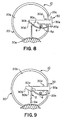
- Figs 7-9 show another embodiment of a single use disposable lancet device according to the present invention.
- the actuator 30 of the device 10 protrudes through a position on the peripheral surface 20c of the housing 20.
- FIGs. 7b-9 shows a view of the second embodiments of the device having the face 20a removed.
- Fig. 7a shows the second embodiment with the face 20a in place. Both faces 20a and 20b are circumferentially reinforced where they meet to form the peripheral surface 20c.
- a spring mechanism 5 is provided within the compartment formed by the housing 20.
- the spring mechanism 5 is pivotally mounted to the inside surface of face 20b and pivots about pivot post 6.
- Pivot post 6 may be a shaft which is mounted to face 20b or may be integrally formed with the face 20b.
- the spring mechanism 5 is formed of spring steel and may be flat or round in cross-section. However, it is envisioned that the spring mechanism could be formed from plastic, composites or other metals.
- a first end 5a of the spring mechanism is sharpened into the form of a point or blade to perform the piercing or cutting operation of the skin.
- the sharpened point or blade is integrally formed with the spring mechanism.
- a needle tip or lancet blade could be fixed to the first end of the spring mechanism.
- the spring mechanism bends at a distinct angle 5b to form an actuation surface 5c against which the actuator 30 biases the spring mechanism 5.
- the spring mechanism preferably raps around pivot 6 which fixes the spring around a point about which to pivot when actuated. Alternatively, the spring mechanism could be fixed at a pivot point without actually wrapping around a shaft.
- a second end 5d of the spring mechanism abuts against a protrusion 20d which is formed in the housing.
- the protrusion 20d acts as a stop to stop the second end of the spring from moving in an upward direction, and prevents the spring from its tendency to move upward as a reaction to the downward biasing of the first end 5a by the actuator 30 via the actuation surface 5c. Accordingly, by stopping the second end as noted, potential energy is stored within the spring mechanism 5 upon downward actuation of the sharpened end.
- a portion of the peripheral surface 20c of the housing 20 is substantially flattened in the areas through which the actuator 30 protrudes.
- the actuator 30 includes an actuation button 30e which is fixed substantially perpendicularly at one end of shaft 30a.
- a biasing portion 30b of the shaft 30a includes a tapered end 30b' for smooth engagement of the actuation surface 5c when the actuator is slid inwardly with respect to the housing.
- the tapered portion 30b' ramps progressively to the outer diameter of the shaft 30a which forms the maximum actuation position of the actuator and spring mechanism, at which position, the sharpened end 5a extends to its maximum position beyond the housing 20.
- the sharpened end 5a is shown in its maximally extended actuation position in Fig. 8.
- the biasing portion 30b of the actuator bypasses actuation surface 5c of the spring mechanism 5, at which time the actuation surface 5c slips off the biasing portion 30b and into notch 30c, into the locking position, as shown in Fig. 9.
- the driving force of the return of the sharpened point 5a into the housing is the potential energy which has been stored in the spring mechanism 5, which is converted to kinetic energy when the spring mechanism 5 is no longer biased by the biasing portion 30b.
- the actuator does not contact the spring mechanism in the initial position, so that the spring rests in a substantially unbiased state in the initial position.
- the shaft 30a is further provided with a flange 30d fixed and extending substantially perpendicularly therefrom, between the notch 30c and button 30e.
- Flange 30d abuts against the inner surface of the housing 20 in the initial position and prevents removal of the actuator 30 from the housing 20, as shown in Fig. 7.
- the compartment formed by faces 20a and 20b are manufactured to a tolerance sufficient to maintain the actuator 30 in alignment with the spring mechanism 5 in this embodiment.
- the lancet operates as follows: The operator grasps the single use disposable lancet device 10 between a thumb and one or more fingers of a single hand. The operator then contacts the skin of a patient to be lanced with the substantially concave contour 20e of the device as shown in Figs. 7a and 7b. To perform the lancing function, the operator depresses button 30e until the button makes contact with the peripheral surface 20c. The operator then removes the lancet device from contact with the patient's skin and disposes of the lancet device, after which the patient's blood sample may be taken and analyzed.
- the entire actuator mechanism 30 moves inwardly with respect to the housing 20 and spring mechanism 5. Because of this relative movement, the spring mechanism is forced to move along the actuating position of the ramped surface 30b' of the biasing portion 30b, and then against the shaft surface actuation portion 30b. This relative movement along the ramped portion and shaft surface causes the biasing mechanism to exert a biasing force against the spring mechanism, which translates to a forced movement of the spring mechanism in a downward direction, thereby driving the sharpened end 5a out of housing 20, through opening 20f and through the skin of the patient as shown in Fig. 8.
- the spring is then returned to the locked position, as described above and as shown in Fig. 9.
- the button 30e contacts the outer surface of the peripheral surface 20c.
- This contact of the button 30e with the peripheral surface 20c is distinctly visible to even a casual observer.
- an operator can readily visibly identify a lancet device which has been sued and needs to be discarded.
- This readily identifiable feature of the device prevents even a second contact of the device with the skin of a second patient, while also positively preventing a re-use of the device.
- Figs. 10-13 show yet another embodiment of a single use disposable lancet device according to the present invention. This embodiment functions substantially similarly to the embodiment shown in Figs. 7-9, with the only difference being in the configuration of the locking device. As such, only the locking device will be specifically described.
- the biasing portion 300b of the actuator bypasses actuation surface 5c of the spring mechanism 5, at which time the actuation surface 5c slips off the biasing portion 300b and into keyway 300c, into the locking position, as shown in Fig. 12.
- the driving force of the return of the sharpened point 5a into the housing is the potential energy which has been stored in the spring mechanism 5, which is converted to kinetic energy when the spring mechanism 5 is no longer biased by the biasing portion 300b.
- the actuator 300 When the spring mechanism 5 rests in the locking position, in a substantially unbiased condition, in keyway 300c, the actuator 300 is effectively prevented from being withdrawn or slid back out of the housing to again assume the initial position. That is, the spring mechanism 5 abuts the surface of the keyway 300c when an attempt is made to withdraw the actuator from the housing. Thus, even if a person tries to physically retract the button 300e away from the housing 20, the person is prevented from doing so because the spring mechanism 5 prevents the outward movement of the actuator with respect to the housing.
- the spring is then returned to the locked position, as described above and as shown in Fig. 12.
- the button 300e contacts the outer surface of the peripheral surface 20c.
- This contact of the button 300e with the peripheral surface 20c is distinctly visible to even a casual observer.
- an operator can readily visibly identify a lancet device which has been used and needs to be discarded.
- This readily identifiable feature of the device prevents even a second contact of the device with the skin of a second patient, while also positively preventing a re-use of the device.
- Fig. 13 shown as side view of the actuator 300 (i.e., in a plane perpendicular to the plane along which the actuator 300 is shown in Fig. 12), to more clearly show the configuration of the keyway 300c (keyway 300c being shown in phantom in Figs. 10-12).
- Keyway 300c is essentially a notch which is cut or otherwise formed into shaft 300a, and which extends entirely therethrough, so as to form a hole through the entire thickness of the shaft 300a.
- Keyway 300c is shaped and dimensioned to readily accept the spring mechanism 5 within and to act as a locking device against which the spring mechanism abuts, should an attempt be made to return the actuator to the initial position.
Landscapes
- Health & Medical Sciences (AREA)
- Life Sciences & Earth Sciences (AREA)
- Heart & Thoracic Surgery (AREA)
- Medical Informatics (AREA)
- Biophysics (AREA)
- Pathology (AREA)
- Engineering & Computer Science (AREA)
- Biomedical Technology (AREA)
- Hematology (AREA)
- Physics & Mathematics (AREA)
- Molecular Biology (AREA)
- Surgery (AREA)
- Animal Behavior & Ethology (AREA)
- General Health & Medical Sciences (AREA)
- Public Health (AREA)
- Veterinary Medicine (AREA)
- Dermatology (AREA)
- Measurement Of The Respiration, Hearing Ability, Form, And Blood Characteristics Of Living Organisms (AREA)
Applications Claiming Priority (2)
| Application Number | Priority Date | Filing Date | Title |
|---|---|---|---|
| US620565 | 1996-03-22 | ||
| US08/620,565 US5643306A (en) | 1996-03-22 | 1996-03-22 | Disposable lancet |
Publications (2)
| Publication Number | Publication Date |
|---|---|
| EP0796592A2 true EP0796592A2 (fr) | 1997-09-24 |
| EP0796592A3 EP0796592A3 (fr) | 1998-06-24 |
Family
ID=24486460
Family Applications (1)
| Application Number | Title | Priority Date | Filing Date |
|---|---|---|---|
| EP97104504A Withdrawn EP0796592A3 (fr) | 1996-03-22 | 1997-03-17 | Dispositif jetable à lancette |
Country Status (3)
| Country | Link |
|---|---|
| US (1) | US5643306A (fr) |
| EP (1) | EP0796592A3 (fr) |
| CA (1) | CA2200502C (fr) |
Cited By (5)
| Publication number | Priority date | Publication date | Assignee | Title |
|---|---|---|---|---|
| DE102004015178A1 (de) * | 2004-03-27 | 2005-10-27 | Balda Medical Gmbh & Co. Kg | Stechvorrichtung, insbesondere Einwegstechhilfe zur Entnahe von Kapillarblut |
| DE102004045043A1 (de) * | 2004-09-15 | 2006-04-13 | Balda Medical Gmbh & Co. Kg | Behandlungsgerät, insbesondere Einwegschneidvorrichtung |
| US7575583B1 (en) | 2000-11-10 | 2009-08-18 | Steven Schraga | Single use lancet device |
| US8353924B2 (en) | 1999-11-02 | 2013-01-15 | Stat Medical Devices, Inc. | Single use lancet assembly |
| US8864783B2 (en) | 2005-08-04 | 2014-10-21 | Bayer Healthcare Llc | Lancing device |
Families Citing this family (131)
| Publication number | Priority date | Publication date | Assignee | Title |
|---|---|---|---|---|
| US6036924A (en) | 1997-12-04 | 2000-03-14 | Hewlett-Packard Company | Cassette of lancet cartridges for sampling blood |
| US6949111B2 (en) | 1998-02-13 | 2005-09-27 | Steven Schraga | Lancet device |
| US6391005B1 (en) | 1998-03-30 | 2002-05-21 | Agilent Technologies, Inc. | Apparatus and method for penetration with shaft having a sensor for sensing penetration depth |
| US7175641B1 (en) | 1998-06-11 | 2007-02-13 | Stat Medical Devices, Inc. | Lancet having adjustable penetration depth |
| DE19840856B4 (de) * | 1998-09-07 | 2008-04-10 | Roche Diagnostics Gmbh | System zur Gewinnung einer Köperflüssigkeit, Lanzettenmagazin, Lanzette, Lanzettensatz, Stechhilfe und Verfahren zur Entnahme einer Lanzette aus einem Lanzettenmagazin sowie Verwendung des Systems |
| US7077828B2 (en) * | 1999-03-05 | 2006-07-18 | Roche Diagnostics Gmbh | Device for withdrawing blood for diagnostic applications |
| US6306152B1 (en) | 1999-03-08 | 2001-10-23 | Agilent Technologies, Inc. | Lancet device with skin movement control and ballistic preload |
| AUPQ089299A0 (en) * | 1999-06-10 | 1999-07-01 | N & V Curie Pty Ltd | Disposable lancet device |
| CA2287757A1 (fr) | 1999-10-29 | 2001-04-29 | Medical Plastic Devices M.P.D. Inc. | Lancette jetable |
| US8814896B2 (en) | 1999-11-02 | 2014-08-26 | Stat Medical Devices, Inc. | Single use lancet assembly |
| US6322575B1 (en) | 2000-01-05 | 2001-11-27 | Steven Schraga | Lancet depth adjustment assembly |
| US6530937B1 (en) * | 2000-01-28 | 2003-03-11 | Stat Medical Devices, Inc. | Adjustable tip for a lancet device and method |
| US7344546B2 (en) * | 2000-04-05 | 2008-03-18 | Pathway Medical Technologies | Intralumenal material removal using a cutting device for differential cutting |
| US6607543B2 (en) * | 2000-06-13 | 2003-08-19 | Bayer Corporation | Lancing mechanism |
| US6561989B2 (en) * | 2000-07-10 | 2003-05-13 | Bayer Healthcare, Llc | Thin lance and test sensor having same |
| US8641644B2 (en) | 2000-11-21 | 2014-02-04 | Sanofi-Aventis Deutschland Gmbh | Blood testing apparatus having a rotatable cartridge with multiple lancing elements and testing means |
| DE10057832C1 (de) * | 2000-11-21 | 2002-02-21 | Hartmann Paul Ag | Blutanalysegerät |
| US7344507B2 (en) | 2002-04-19 | 2008-03-18 | Pelikan Technologies, Inc. | Method and apparatus for lancet actuation |
| WO2002100461A2 (fr) | 2001-06-12 | 2002-12-19 | Pelikan Technologies, Inc. | Dispositif et procede permettant d'ameliorer le rendement du prelevement de sang capillaire au bout du doigt |
| US9427532B2 (en) | 2001-06-12 | 2016-08-30 | Sanofi-Aventis Deutschland Gmbh | Tissue penetration device |
| US7981056B2 (en) | 2002-04-19 | 2011-07-19 | Pelikan Technologies, Inc. | Methods and apparatus for lancet actuation |
| US8337419B2 (en) | 2002-04-19 | 2012-12-25 | Sanofi-Aventis Deutschland Gmbh | Tissue penetration device |
| US7537571B2 (en) | 2001-06-12 | 2009-05-26 | Pelikan Technologies, Inc. | Integrated blood sampling analysis system with multi-use sampling module |
| US7041068B2 (en) | 2001-06-12 | 2006-05-09 | Pelikan Technologies, Inc. | Sampling module device and method |
| US7682318B2 (en) | 2001-06-12 | 2010-03-23 | Pelikan Technologies, Inc. | Blood sampling apparatus and method |
| US9226699B2 (en) | 2002-04-19 | 2016-01-05 | Sanofi-Aventis Deutschland Gmbh | Body fluid sampling module with a continuous compression tissue interface surface |
| AU2002348683A1 (en) | 2001-06-12 | 2002-12-23 | Pelikan Technologies, Inc. | Method and apparatus for lancet launching device integrated onto a blood-sampling cartridge |
| WO2002100460A2 (fr) | 2001-06-12 | 2002-12-19 | Pelikan Technologies, Inc. | Actionneur electrique de lancette |
| CA2448902C (fr) | 2001-06-12 | 2010-09-07 | Pelikan Technologies, Inc. | Autopiqueur a optimisation automatique presentant des moyens d'adaptation aux variations temporelles des proprietes cutanees |
| US9795747B2 (en) | 2010-06-02 | 2017-10-24 | Sanofi-Aventis Deutschland Gmbh | Methods and apparatus for lancet actuation |
| PL193168B1 (pl) * | 2001-08-13 | 2007-01-31 | Htl Strefa Sp Z Oo | Lancet |
| US8048097B2 (en) | 2001-08-14 | 2011-11-01 | Steven Schraga | Single use lancet assembly |
| US6918918B1 (en) | 2001-08-14 | 2005-07-19 | Steven Schraga | Single use lancet assembly |
| US7344894B2 (en) | 2001-10-16 | 2008-03-18 | Agilent Technologies, Inc. | Thermal regulation of fluidic samples within a diagnostic cartridge |
| US8360992B2 (en) | 2002-04-19 | 2013-01-29 | Sanofi-Aventis Deutschland Gmbh | Method and apparatus for penetrating tissue |
| US7141058B2 (en) | 2002-04-19 | 2006-11-28 | Pelikan Technologies, Inc. | Method and apparatus for a body fluid sampling device using illumination |
| US7297122B2 (en) | 2002-04-19 | 2007-11-20 | Pelikan Technologies, Inc. | Method and apparatus for penetrating tissue |
| US8784335B2 (en) | 2002-04-19 | 2014-07-22 | Sanofi-Aventis Deutschland Gmbh | Body fluid sampling device with a capacitive sensor |
| AU2003231749A1 (en) | 2002-04-19 | 2003-11-03 | Pelikan Technologies, Inc. | Device and method for variable speed lancet |
| US7374544B2 (en) | 2002-04-19 | 2008-05-20 | Pelikan Technologies, Inc. | Method and apparatus for penetrating tissue |
| US7524293B2 (en) | 2002-04-19 | 2009-04-28 | Pelikan Technologies, Inc. | Method and apparatus for penetrating tissue |
| US7892185B2 (en) | 2002-04-19 | 2011-02-22 | Pelikan Technologies, Inc. | Method and apparatus for body fluid sampling and analyte sensing |
| US9248267B2 (en) | 2002-04-19 | 2016-02-02 | Sanofi-Aventis Deustchland Gmbh | Tissue penetration device |
| US8702624B2 (en) | 2006-09-29 | 2014-04-22 | Sanofi-Aventis Deutschland Gmbh | Analyte measurement device with a single shot actuator |
| US7371247B2 (en) | 2002-04-19 | 2008-05-13 | Pelikan Technologies, Inc | Method and apparatus for penetrating tissue |
| US9795334B2 (en) | 2002-04-19 | 2017-10-24 | Sanofi-Aventis Deutschland Gmbh | Method and apparatus for penetrating tissue |
| US7717863B2 (en) | 2002-04-19 | 2010-05-18 | Pelikan Technologies, Inc. | Method and apparatus for penetrating tissue |
| US7909778B2 (en) | 2002-04-19 | 2011-03-22 | Pelikan Technologies, Inc. | Method and apparatus for penetrating tissue |
| US7892183B2 (en) | 2002-04-19 | 2011-02-22 | Pelikan Technologies, Inc. | Method and apparatus for body fluid sampling and analyte sensing |
| US7648468B2 (en) | 2002-04-19 | 2010-01-19 | Pelikon Technologies, Inc. | Method and apparatus for penetrating tissue |
| US7291117B2 (en) | 2002-04-19 | 2007-11-06 | Pelikan Technologies, Inc. | Method and apparatus for penetrating tissue |
| US7976476B2 (en) | 2002-04-19 | 2011-07-12 | Pelikan Technologies, Inc. | Device and method for variable speed lancet |
| US7491178B2 (en) | 2002-04-19 | 2009-02-17 | Pelikan Technologies, Inc. | Method and apparatus for penetrating tissue |
| US7232451B2 (en) | 2002-04-19 | 2007-06-19 | Pelikan Technologies, Inc. | Method and apparatus for penetrating tissue |
| US9314194B2 (en) | 2002-04-19 | 2016-04-19 | Sanofi-Aventis Deutschland Gmbh | Tissue penetration device |
| US7331931B2 (en) | 2002-04-19 | 2008-02-19 | Pelikan Technologies, Inc. | Method and apparatus for penetrating tissue |
| US7901362B2 (en) | 2002-04-19 | 2011-03-08 | Pelikan Technologies, Inc. | Method and apparatus for penetrating tissue |
| US8221334B2 (en) | 2002-04-19 | 2012-07-17 | Sanofi-Aventis Deutschland Gmbh | Method and apparatus for penetrating tissue |
| US7229458B2 (en) | 2002-04-19 | 2007-06-12 | Pelikan Technologies, Inc. | Method and apparatus for penetrating tissue |
| US7547287B2 (en) | 2002-04-19 | 2009-06-16 | Pelikan Technologies, Inc. | Method and apparatus for penetrating tissue |
| US7226461B2 (en) | 2002-04-19 | 2007-06-05 | Pelikan Technologies, Inc. | Method and apparatus for a multi-use body fluid sampling device with sterility barrier release |
| US7244265B2 (en) | 2002-04-19 | 2007-07-17 | Pelikan Technologies, Inc. | Method and apparatus for penetrating tissue |
| US7485128B2 (en) | 2002-04-19 | 2009-02-03 | Pelikan Technologies, Inc. | Method and apparatus for penetrating tissue |
| US8267870B2 (en) | 2002-04-19 | 2012-09-18 | Sanofi-Aventis Deutschland Gmbh | Method and apparatus for body fluid sampling with hybrid actuation |
| US7563232B2 (en) | 2002-04-19 | 2009-07-21 | Pelikan Technologies, Inc. | Method and apparatus for penetrating tissue |
| US7410468B2 (en) | 2002-04-19 | 2008-08-12 | Pelikan Technologies, Inc. | Method and apparatus for penetrating tissue |
| US7674232B2 (en) | 2002-04-19 | 2010-03-09 | Pelikan Technologies, Inc. | Method and apparatus for penetrating tissue |
| US8579831B2 (en) | 2002-04-19 | 2013-11-12 | Sanofi-Aventis Deutschland Gmbh | Method and apparatus for penetrating tissue |
| US20040039407A1 (en) | 2002-04-29 | 2004-02-26 | Steven Schraga | Lancet device |
| US8715309B2 (en) | 2002-04-29 | 2014-05-06 | Steven Schraga | Lancet device |
| DE10222235A1 (de) * | 2002-05-16 | 2003-11-27 | Roche Diagnostics Gmbh | Blutentnahmesystem |
| DE10223558A1 (de) * | 2002-05-28 | 2003-12-11 | Roche Diagnostics Gmbh | Blutentnahmesystem |
| US8574895B2 (en) | 2002-12-30 | 2013-11-05 | Sanofi-Aventis Deutschland Gmbh | Method and apparatus using optical techniques to measure analyte levels |
| US7621931B2 (en) * | 2003-05-20 | 2009-11-24 | Stat Medical Devices, Inc. | Adjustable lancet device and method |
| EP2238892A3 (fr) | 2003-05-30 | 2011-02-09 | Pelikan Technologies Inc. | Appareil pour prendre de fluide du corps |
| ES2490740T3 (es) | 2003-06-06 | 2014-09-04 | Sanofi-Aventis Deutschland Gmbh | Aparato para toma de muestras de fluido sanguíneo y detección de analitos |
| WO2006001797A1 (fr) | 2004-06-14 | 2006-01-05 | Pelikan Technologies, Inc. | Element penetrant peu douloureux |
| US7604592B2 (en) | 2003-06-13 | 2009-10-20 | Pelikan Technologies, Inc. | Method and apparatus for a point of care device |
| US7905898B2 (en) * | 2003-08-15 | 2011-03-15 | Stat Medical Devices, Inc. | Adjustable lancet device and method |
| US7105006B2 (en) | 2003-08-15 | 2006-09-12 | Stat Medical Devices, Inc. | Adjustable lancet device and method |
| JP3100042U (ja) * | 2003-08-26 | 2004-04-30 | アルプス電気株式会社 | テレビジョンチューナ |
| EP1670368A4 (fr) * | 2003-09-18 | 2009-08-05 | Facet Technologies Llc | Autopiqueur comprenant une coiffe terminale pivotante |
| EP1671096A4 (fr) | 2003-09-29 | 2009-09-16 | Pelikan Technologies Inc | Procede et appareil permettant d'obtenir un dispositif de capture d'echantillons ameliore |
| EP1680014A4 (fr) | 2003-10-14 | 2009-01-21 | Pelikan Technologies Inc | Procede et appareil fournissant une interface-utilisateur variable |
| WO2005065414A2 (fr) | 2003-12-31 | 2005-07-21 | Pelikan Technologies, Inc. | Procede et appareil permettant d'ameliorer le flux fluidique et le prelevement d'echantillons |
| US7822454B1 (en) | 2005-01-03 | 2010-10-26 | Pelikan Technologies, Inc. | Fluid sampling device with improved analyte detecting member configuration |
| US9066688B2 (en) * | 2004-05-07 | 2015-06-30 | Becton, Dickinson And Company | Contact activated lancet device |
| US9380975B2 (en) * | 2004-05-07 | 2016-07-05 | Becton, Dickinson And Company | Contact activated lancet device |
| US8828203B2 (en) | 2004-05-20 | 2014-09-09 | Sanofi-Aventis Deutschland Gmbh | Printable hydrogels for biosensors |
| US9775553B2 (en) | 2004-06-03 | 2017-10-03 | Sanofi-Aventis Deutschland Gmbh | Method and apparatus for a fluid sampling device |
| EP1765194A4 (fr) | 2004-06-03 | 2010-09-29 | Pelikan Technologies Inc | Procede et appareil pour la fabrication d'un dispositif d'echantillonnage de liquides |
| US8257380B2 (en) * | 2004-06-29 | 2012-09-04 | Stat Medical Devices, Inc. | Adjustabable disposable/single-use lancet device and method |
| US8105347B2 (en) * | 2004-11-16 | 2012-01-31 | Stat Medical Devices, Inc. | Adjustable disposable/single-use blade lancet device and method |
| US8066728B2 (en) * | 2004-11-30 | 2011-11-29 | Stat Medical Devices, Inc. | Disposable or single-use lancet device and method |
| DE102004058164B4 (de) * | 2004-12-02 | 2009-04-16 | Roche Diagnostics Gmbh | Stechvorrichtung zur Entnahme von Blut und Verfahren zur Herstellung dafür |
| US8652831B2 (en) | 2004-12-30 | 2014-02-18 | Sanofi-Aventis Deutschland Gmbh | Method and apparatus for analyte measurement test time |
| US8934955B2 (en) * | 2005-01-18 | 2015-01-13 | Stat Medical Devices, Inc. | Cartridge with lancets and test strips and testing device using the cartridge |
| US9289161B2 (en) | 2005-01-28 | 2016-03-22 | Stat Medical Divices, Inc. | Multi-lancet unit, method and lancet device using the multi-lancet unit, and method of assembling and/or making the multi-lancet unit |
| ES2425927T3 (es) | 2005-04-07 | 2013-10-18 | Becton, Dickinson And Company | Dispositivo de lanceta |
| CN101179993B (zh) * | 2005-04-07 | 2011-10-05 | 贝克顿·迪金森公司 | 触发器启动的刺血针 |
| US8211036B2 (en) * | 2005-05-27 | 2012-07-03 | Stat Medical Devices, Inc. | Disposable lancet device cap with integral lancet and/or test strip and testing device utilizing the cap |
| EP1743700B1 (fr) * | 2005-07-15 | 2008-10-01 | Dentaco Dentalindustrie und -marketing GmbH | Dispositif de pipetage |
| US7704265B2 (en) * | 2005-11-03 | 2010-04-27 | Stat Medical Devices, Inc. | Disposable/single-use blade lancet device and method |
| US8303614B2 (en) * | 2005-12-21 | 2012-11-06 | Stat Medical Devices, Inc. | Double-ended lancet, method and lancet device using the double-ended lancet, and method of assembling and/or making the double-ended lancet |
| US20080092241A1 (en) * | 2006-10-11 | 2008-04-17 | Media Machines, Inc. | Provision and use of digital rights data for embedded content over networked systems |
| US20100168616A1 (en) * | 2006-11-21 | 2010-07-01 | Stat Medical Devices, Inc. | Lancet device utilizing a revolver-type cartridge, revolver-type cartridge, and method of making and/or using the cartridge and the lancet device |
| US8043318B2 (en) | 2007-02-08 | 2011-10-25 | Stat Medical Devices, Inc. | Push-button lance device and method |
| WO2008100818A1 (fr) * | 2007-02-09 | 2008-08-21 | Stat Medical Devices, Inc | Unité multi-lancettes, procédé et dispositif de lancette comprenant l'unité multi-lancettes, procédé d'assemblage et ou de fabrication de l'unité multi-lancettes |
| US8469986B2 (en) * | 2007-03-30 | 2013-06-25 | Stat Medical Devices, Inc. | Lancet device with combined trigger and cocking mechanism and method |
| US9179867B2 (en) * | 2007-06-19 | 2015-11-10 | Stat Medical Devices, Inc. | Lancet device with depth adjustment and lancet removal system and method |
| US9392968B2 (en) * | 2008-01-23 | 2016-07-19 | Stat Medical Devices, Inc. | Lancet needle cartridge, cartridge lancet device, and method of using and making the same |
| US20090204027A1 (en) * | 2008-02-11 | 2009-08-13 | Zuk Robert F | Lancet with shielded lance |
| EP2265324B1 (fr) | 2008-04-11 | 2015-01-28 | Sanofi-Aventis Deutschland GmbH | Système intégré de mesure d'analytes |
| US9375169B2 (en) | 2009-01-30 | 2016-06-28 | Sanofi-Aventis Deutschland Gmbh | Cam drive for managing disposable penetrating member actions with a single motor and motor and control system |
| WO2010091137A2 (fr) * | 2009-02-06 | 2010-08-12 | Mayo Foundation For Medical Education And Research | Aiguille isomark |
| US8317812B2 (en) | 2009-07-29 | 2012-11-27 | Wah Leong Lum | Lancet device with lance retraction |
| US20110040316A1 (en) * | 2009-08-17 | 2011-02-17 | Sanford Research/USD | Method and Apparatus for a Single Handed Squeeze Lancet |
| US8965476B2 (en) | 2010-04-16 | 2015-02-24 | Sanofi-Aventis Deutschland Gmbh | Tissue penetration device |
| WO2012046231A2 (fr) * | 2010-10-04 | 2012-04-12 | Nervomatrix Ltd. | Electrode pour trouver des points de faible impédance et appliquer une stimulation électrique sur ceux-ci |
| SG182858A1 (en) * | 2011-01-07 | 2012-08-30 | Wah Leong Lum | Contact activated incision device |
| US9113956B2 (en) | 2011-02-25 | 2015-08-25 | Mayo Foundation For Medical Education And Research | Isomark tattooing devices |
| AP2016009385A0 (en) | 2014-01-28 | 2016-08-31 | Intrinsyk Llc | Lancet assembly |
| WO2015116698A1 (fr) | 2014-01-29 | 2015-08-06 | Intrinsyk Llc | Procédé et système de fourniture d'une lancette de sécurité à usage unique |
| USD742004S1 (en) | 2014-02-18 | 2015-10-27 | “HTL-STREFA” Spólka Akcyjna | Skin incision device |
| US9610402B2 (en) * | 2014-03-24 | 2017-04-04 | Medtronic Minimed, Inc. | Transcutaneous conduit insertion mechanism with a living hinge for use with a fluid infusion patch pump device |
| US10070811B2 (en) | 2014-06-26 | 2018-09-11 | Stat Medical Devices, Inc. | Lancing device with depth adjustment and lancet removal system and method |
| US9743876B2 (en) | 2014-07-18 | 2017-08-29 | Becton, Dickinson And Company | Lancet device with first-drop removal |
| USD806246S1 (en) | 2016-02-25 | 2017-12-26 | Steven Schraga | Lancet cover |
| USD806864S1 (en) * | 2016-08-19 | 2018-01-02 | Sterilance Medical (Suzhou) Inc. | Disposable heel blood collecting device |
| AU2022205919A1 (en) * | 2021-01-05 | 2023-07-20 | Becton, Dickinson And Company | Needle hub and applicator for drug delivery device |
| USD1010823S1 (en) * | 2021-11-26 | 2024-01-09 | Asahi Polyslider Company, Limited | Lancet |
Family Cites Families (18)
| Publication number | Priority date | Publication date | Assignee | Title |
|---|---|---|---|---|
| US4414975A (en) * | 1981-05-15 | 1983-11-15 | Ryder International Corp. | Blood lancet |
| US4449529A (en) * | 1981-11-18 | 1984-05-22 | Becton Dickinson And Company | Automatic retractable lancet assembly |
| US4628929A (en) * | 1985-08-16 | 1986-12-16 | American Hospital Supply Corporation | Retractable blade bleeding time device |
| US4794926A (en) * | 1986-11-24 | 1989-01-03 | Invictus, Inc. | Lancet cartridge |
| GB8710470D0 (en) * | 1987-05-01 | 1987-06-03 | Mumford Ltd Owen | Blood sampling devices |
| US4892097A (en) * | 1988-02-09 | 1990-01-09 | Ryder International Corporation | Retractable finger lancet |
| US4889117A (en) * | 1989-02-17 | 1989-12-26 | Stevens Peter A | Disposable lancet |
| US5054499A (en) * | 1989-03-27 | 1991-10-08 | Swierczek Remi D | Disposable skin perforator and blood testing device |
| SE465012B (sv) * | 1989-12-08 | 1991-07-15 | Freja Invest Kommanditbolag | Haaltagningshjaelpmedel foer aastadkommande av punktering av kroppsdelar |
| US5133730A (en) * | 1991-05-15 | 1992-07-28 | International Technidyne Corporation | Disposable-retractable finger stick device |
| US5402798A (en) * | 1991-07-18 | 1995-04-04 | Swierczek; Remi | Disposable skin perforator and blood testing device |
| DE69229180T2 (de) * | 1991-11-12 | 1999-10-14 | Urs. A. Ramel | Lanzetteneinrichtung |
| PL169210B1 (pl) * | 1992-08-03 | 1996-06-28 | Przed Zagraniczne Htl | Przyrzad do nakluwania PL |
| US5269800A (en) * | 1992-12-10 | 1993-12-14 | Davis Manufacturing Systems Inc. | Blood lancing device |
| US5395388A (en) * | 1993-11-15 | 1995-03-07 | Schraga; Steven | Single unit lancet device |
| US5439473A (en) * | 1993-12-13 | 1995-08-08 | Modulohm A/S | Safety lancet |
| US5454828A (en) * | 1994-03-16 | 1995-10-03 | Schraga; Steven | Lancet unit with safety sleeve |
| US5476474A (en) * | 1994-07-27 | 1995-12-19 | Ryder International Corporation | Rotary lancet |
-
1996
- 1996-03-22 US US08/620,565 patent/US5643306A/en not_active Expired - Lifetime
-
1997
- 1997-03-17 EP EP97104504A patent/EP0796592A3/fr not_active Withdrawn
- 1997-03-20 CA CA002200502A patent/CA2200502C/fr not_active Expired - Fee Related
Cited By (8)
| Publication number | Priority date | Publication date | Assignee | Title |
|---|---|---|---|---|
| US8353924B2 (en) | 1999-11-02 | 2013-01-15 | Stat Medical Devices, Inc. | Single use lancet assembly |
| US7575583B1 (en) | 2000-11-10 | 2009-08-18 | Steven Schraga | Single use lancet device |
| DE102004015178A1 (de) * | 2004-03-27 | 2005-10-27 | Balda Medical Gmbh & Co. Kg | Stechvorrichtung, insbesondere Einwegstechhilfe zur Entnahe von Kapillarblut |
| DE102004015178B4 (de) * | 2004-03-27 | 2007-11-22 | Balda Medical Gmbh & Co. Kg | Stechvorrichtung, insbesondere Einwegstechhilfe zur Entnahe von Kapillarblut |
| DE102004045043A1 (de) * | 2004-09-15 | 2006-04-13 | Balda Medical Gmbh & Co. Kg | Behandlungsgerät, insbesondere Einwegschneidvorrichtung |
| DE102004045043B4 (de) * | 2004-09-15 | 2013-09-12 | Balda Medical Gmbh & Co. Kg | Behandlungsgerät zur Blutgewinnung |
| US8864783B2 (en) | 2005-08-04 | 2014-10-21 | Bayer Healthcare Llc | Lancing device |
| US9375175B2 (en) | 2005-08-04 | 2016-06-28 | Ascensia Diabetes Care Holdings Ag | Lancing device |
Also Published As
| Publication number | Publication date |
|---|---|
| MX9702122A (es) | 1997-09-30 |
| CA2200502C (fr) | 2000-09-19 |
| US5643306A (en) | 1997-07-01 |
| EP0796592A3 (fr) | 1998-06-24 |
| CA2200502A1 (fr) | 1997-09-22 |
Similar Documents
| Publication | Publication Date | Title |
|---|---|---|
| US5643306A (en) | Disposable lancet | |
| US20020087180A1 (en) | Blood lancet | |
| US5571132A (en) | Self activated finger lancet | |
| EP0189117B1 (fr) | Lancette | |
| USRE32922E (en) | Blood sampling instrument | |
| US5395388A (en) | Single unit lancet device | |
| US4414975A (en) | Blood lancet | |
| US9179867B2 (en) | Lancet device with depth adjustment and lancet removal system and method | |
| US4990154A (en) | Lancet assembly | |
| US5133730A (en) | Disposable-retractable finger stick device | |
| CN101849830B (zh) | 接触致动的刺血针装置 | |
| US7811302B2 (en) | Lancet device for puncturing the skin | |
| US4889117A (en) | Disposable lancet | |
| US5611809A (en) | Needle devices for medical use | |
| EP0115388A1 (fr) | Dispositif de prise d'échantillons sanguins | |
| KR101379350B1 (ko) | 피부 천공 장치 | |
| EP1652474A2 (fr) | Dispositif combiné autopiqueur et dispositif auxiliaire | |
| US5571128A (en) | Safety surgical instrument | |
| US20070293882A1 (en) | Pricking device for taking blood | |
| US9066688B2 (en) | Contact activated lancet device | |
| JPH03141929A (ja) | ランセツト押し出し機構 | |
| JP2013128560A (ja) | ランセットアッセンブリおよび穿刺デバイス | |
| CN102481125A (zh) | 一次性采血器具 | |
| EP2378952B1 (fr) | Instrument de perforation | |
| KR101201034B1 (ko) | 환자용 피부천자기 |
Legal Events
| Date | Code | Title | Description |
|---|---|---|---|
| PUAI | Public reference made under article 153(3) epc to a published international application that has entered the european phase |
Free format text: ORIGINAL CODE: 0009012 |
|
| AK | Designated contracting states |
Kind code of ref document: A2 Designated state(s): AT BE CH DE DK ES FR GB IE IT LI NL SE |
|
| PUAL | Search report despatched |
Free format text: ORIGINAL CODE: 0009013 |
|
| AK | Designated contracting states |
Kind code of ref document: A3 Designated state(s): AT BE CH DE DK ES FR GB IE IT LI NL SE |
|
| 17P | Request for examination filed |
Effective date: 19981207 |
|
| 17Q | First examination report despatched |
Effective date: 19990825 |
|
| GRAG | Despatch of communication of intention to grant |
Free format text: ORIGINAL CODE: EPIDOS AGRA |
|
| GRAG | Despatch of communication of intention to grant |
Free format text: ORIGINAL CODE: EPIDOS AGRA |
|
| GRAH | Despatch of communication of intention to grant a patent |
Free format text: ORIGINAL CODE: EPIDOS IGRA |
|
| STAA | Information on the status of an ep patent application or granted ep patent |
Free format text: STATUS: THE APPLICATION IS DEEMED TO BE WITHDRAWN |
|
| 18D | Application deemed to be withdrawn |
Effective date: 20011006 |