EP0796598B1 - Prothetische Gelenkpfanne - Google Patents
Prothetische Gelenkpfanne Download PDFInfo
- Publication number
- EP0796598B1 EP0796598B1 EP97103833A EP97103833A EP0796598B1 EP 0796598 B1 EP0796598 B1 EP 0796598B1 EP 97103833 A EP97103833 A EP 97103833A EP 97103833 A EP97103833 A EP 97103833A EP 0796598 B1 EP0796598 B1 EP 0796598B1
- Authority
- EP
- European Patent Office
- Prior art keywords
- shell
- outer shell
- insert
- prosthetic joint
- cone
- Prior art date
- Legal status (The legal status is an assumption and is not a legal conclusion. Google has not performed a legal analysis and makes no representation as to the accuracy of the status listed.)
- Expired - Lifetime
Links
Images
Classifications
-
- A—HUMAN NECESSITIES
- A61—MEDICAL OR VETERINARY SCIENCE; HYGIENE
- A61F—FILTERS IMPLANTABLE INTO BLOOD VESSELS; PROSTHESES; DEVICES PROVIDING PATENCY TO, OR PREVENTING COLLAPSING OF, TUBULAR STRUCTURES OF THE BODY, e.g. STENTS; ORTHOPAEDIC, NURSING OR CONTRACEPTIVE DEVICES; FOMENTATION; TREATMENT OR PROTECTION OF EYES OR EARS; BANDAGES, DRESSINGS OR ABSORBENT PADS; FIRST-AID KITS
- A61F2/00—Filters implantable into blood vessels; Prostheses, i.e. artificial substitutes or replacements for parts of the body; Appliances for connecting them with the body; Devices providing patency to, or preventing collapsing of, tubular structures of the body, e.g. stents
- A61F2/02—Prostheses implantable into the body
- A61F2/30—Joints
- A61F2/32—Joints for the hip
- A61F2/34—Acetabular cups
-
- A—HUMAN NECESSITIES
- A61—MEDICAL OR VETERINARY SCIENCE; HYGIENE
- A61F—FILTERS IMPLANTABLE INTO BLOOD VESSELS; PROSTHESES; DEVICES PROVIDING PATENCY TO, OR PREVENTING COLLAPSING OF, TUBULAR STRUCTURES OF THE BODY, e.g. STENTS; ORTHOPAEDIC, NURSING OR CONTRACEPTIVE DEVICES; FOMENTATION; TREATMENT OR PROTECTION OF EYES OR EARS; BANDAGES, DRESSINGS OR ABSORBENT PADS; FIRST-AID KITS
- A61F2/00—Filters implantable into blood vessels; Prostheses, i.e. artificial substitutes or replacements for parts of the body; Appliances for connecting them with the body; Devices providing patency to, or preventing collapsing of, tubular structures of the body, e.g. stents
- A61F2/02—Prostheses implantable into the body
- A61F2/30—Joints
- A61F2/46—Special tools for implanting artificial joints
- A61F2/4637—Special tools for implanting artificial joints for connecting or disconnecting two parts of a prosthesis
-
- A—HUMAN NECESSITIES
- A61—MEDICAL OR VETERINARY SCIENCE; HYGIENE
- A61F—FILTERS IMPLANTABLE INTO BLOOD VESSELS; PROSTHESES; DEVICES PROVIDING PATENCY TO, OR PREVENTING COLLAPSING OF, TUBULAR STRUCTURES OF THE BODY, e.g. STENTS; ORTHOPAEDIC, NURSING OR CONTRACEPTIVE DEVICES; FOMENTATION; TREATMENT OR PROTECTION OF EYES OR EARS; BANDAGES, DRESSINGS OR ABSORBENT PADS; FIRST-AID KITS
- A61F2/00—Filters implantable into blood vessels; Prostheses, i.e. artificial substitutes or replacements for parts of the body; Appliances for connecting them with the body; Devices providing patency to, or preventing collapsing of, tubular structures of the body, e.g. stents
- A61F2/02—Prostheses implantable into the body
- A61F2/30—Joints
- A61F2002/30001—Additional features of subject-matter classified in A61F2/28, A61F2/30 and subgroups thereof
- A61F2002/30316—The prosthesis having different structural features at different locations within the same prosthesis; Connections between prosthetic parts; Special structural features of bone or joint prostheses not otherwise provided for
- A61F2002/30329—Connections or couplings between prosthetic parts, e.g. between modular parts; Connecting elements
- A61F2002/30331—Connections or couplings between prosthetic parts, e.g. between modular parts; Connecting elements made by longitudinally pushing a protrusion into a complementarily-shaped recess, e.g. held by friction fit
-
- A—HUMAN NECESSITIES
- A61—MEDICAL OR VETERINARY SCIENCE; HYGIENE
- A61F—FILTERS IMPLANTABLE INTO BLOOD VESSELS; PROSTHESES; DEVICES PROVIDING PATENCY TO, OR PREVENTING COLLAPSING OF, TUBULAR STRUCTURES OF THE BODY, e.g. STENTS; ORTHOPAEDIC, NURSING OR CONTRACEPTIVE DEVICES; FOMENTATION; TREATMENT OR PROTECTION OF EYES OR EARS; BANDAGES, DRESSINGS OR ABSORBENT PADS; FIRST-AID KITS
- A61F2/00—Filters implantable into blood vessels; Prostheses, i.e. artificial substitutes or replacements for parts of the body; Appliances for connecting them with the body; Devices providing patency to, or preventing collapsing of, tubular structures of the body, e.g. stents
- A61F2/02—Prostheses implantable into the body
- A61F2/30—Joints
- A61F2002/30001—Additional features of subject-matter classified in A61F2/28, A61F2/30 and subgroups thereof
- A61F2002/30316—The prosthesis having different structural features at different locations within the same prosthesis; Connections between prosthetic parts; Special structural features of bone or joint prostheses not otherwise provided for
- A61F2002/30329—Connections or couplings between prosthetic parts, e.g. between modular parts; Connecting elements
- A61F2002/30331—Connections or couplings between prosthetic parts, e.g. between modular parts; Connecting elements made by longitudinally pushing a protrusion into a complementarily-shaped recess, e.g. held by friction fit
- A61F2002/30332—Conically- or frustoconically-shaped protrusion and recess
-
- A—HUMAN NECESSITIES
- A61—MEDICAL OR VETERINARY SCIENCE; HYGIENE
- A61F—FILTERS IMPLANTABLE INTO BLOOD VESSELS; PROSTHESES; DEVICES PROVIDING PATENCY TO, OR PREVENTING COLLAPSING OF, TUBULAR STRUCTURES OF THE BODY, e.g. STENTS; ORTHOPAEDIC, NURSING OR CONTRACEPTIVE DEVICES; FOMENTATION; TREATMENT OR PROTECTION OF EYES OR EARS; BANDAGES, DRESSINGS OR ABSORBENT PADS; FIRST-AID KITS
- A61F2/00—Filters implantable into blood vessels; Prostheses, i.e. artificial substitutes or replacements for parts of the body; Appliances for connecting them with the body; Devices providing patency to, or preventing collapsing of, tubular structures of the body, e.g. stents
- A61F2/02—Prostheses implantable into the body
- A61F2/30—Joints
- A61F2002/30001—Additional features of subject-matter classified in A61F2/28, A61F2/30 and subgroups thereof
- A61F2002/30316—The prosthesis having different structural features at different locations within the same prosthesis; Connections between prosthetic parts; Special structural features of bone or joint prostheses not otherwise provided for
- A61F2002/30329—Connections or couplings between prosthetic parts, e.g. between modular parts; Connecting elements
- A61F2002/30331—Connections or couplings between prosthetic parts, e.g. between modular parts; Connecting elements made by longitudinally pushing a protrusion into a complementarily-shaped recess, e.g. held by friction fit
- A61F2002/30332—Conically- or frustoconically-shaped protrusion and recess
- A61F2002/30345—Multiple conical connection, i.e. the protrusion and recess having several tapered sections of different complementary conicities
-
- A—HUMAN NECESSITIES
- A61—MEDICAL OR VETERINARY SCIENCE; HYGIENE
- A61F—FILTERS IMPLANTABLE INTO BLOOD VESSELS; PROSTHESES; DEVICES PROVIDING PATENCY TO, OR PREVENTING COLLAPSING OF, TUBULAR STRUCTURES OF THE BODY, e.g. STENTS; ORTHOPAEDIC, NURSING OR CONTRACEPTIVE DEVICES; FOMENTATION; TREATMENT OR PROTECTION OF EYES OR EARS; BANDAGES, DRESSINGS OR ABSORBENT PADS; FIRST-AID KITS
- A61F2/00—Filters implantable into blood vessels; Prostheses, i.e. artificial substitutes or replacements for parts of the body; Appliances for connecting them with the body; Devices providing patency to, or preventing collapsing of, tubular structures of the body, e.g. stents
- A61F2/02—Prostheses implantable into the body
- A61F2/30—Joints
- A61F2002/30001—Additional features of subject-matter classified in A61F2/28, A61F2/30 and subgroups thereof
- A61F2002/30316—The prosthesis having different structural features at different locations within the same prosthesis; Connections between prosthetic parts; Special structural features of bone or joint prostheses not otherwise provided for
- A61F2002/30535—Special structural features of bone or joint prostheses not otherwise provided for
- A61F2002/30593—Special structural features of bone or joint prostheses not otherwise provided for hollow
-
- A—HUMAN NECESSITIES
- A61—MEDICAL OR VETERINARY SCIENCE; HYGIENE
- A61F—FILTERS IMPLANTABLE INTO BLOOD VESSELS; PROSTHESES; DEVICES PROVIDING PATENCY TO, OR PREVENTING COLLAPSING OF, TUBULAR STRUCTURES OF THE BODY, e.g. STENTS; ORTHOPAEDIC, NURSING OR CONTRACEPTIVE DEVICES; FOMENTATION; TREATMENT OR PROTECTION OF EYES OR EARS; BANDAGES, DRESSINGS OR ABSORBENT PADS; FIRST-AID KITS
- A61F2/00—Filters implantable into blood vessels; Prostheses, i.e. artificial substitutes or replacements for parts of the body; Appliances for connecting them with the body; Devices providing patency to, or preventing collapsing of, tubular structures of the body, e.g. stents
- A61F2/02—Prostheses implantable into the body
- A61F2/30—Joints
- A61F2/30767—Special external or bone-contacting surface, e.g. coating for improving bone ingrowth
- A61F2/30771—Special external or bone-contacting surface, e.g. coating for improving bone ingrowth applied in original prostheses, e.g. holes or grooves
- A61F2002/30795—Blind bores, e.g. of circular cross-section
-
- A—HUMAN NECESSITIES
- A61—MEDICAL OR VETERINARY SCIENCE; HYGIENE
- A61F—FILTERS IMPLANTABLE INTO BLOOD VESSELS; PROSTHESES; DEVICES PROVIDING PATENCY TO, OR PREVENTING COLLAPSING OF, TUBULAR STRUCTURES OF THE BODY, e.g. STENTS; ORTHOPAEDIC, NURSING OR CONTRACEPTIVE DEVICES; FOMENTATION; TREATMENT OR PROTECTION OF EYES OR EARS; BANDAGES, DRESSINGS OR ABSORBENT PADS; FIRST-AID KITS
- A61F2/00—Filters implantable into blood vessels; Prostheses, i.e. artificial substitutes or replacements for parts of the body; Appliances for connecting them with the body; Devices providing patency to, or preventing collapsing of, tubular structures of the body, e.g. stents
- A61F2/02—Prostheses implantable into the body
- A61F2/30—Joints
- A61F2/46—Special tools for implanting artificial joints
- A61F2/4637—Special tools for implanting artificial joints for connecting or disconnecting two parts of a prosthesis
- A61F2002/4641—Special tools for implanting artificial joints for connecting or disconnecting two parts of a prosthesis for disconnecting
-
- A—HUMAN NECESSITIES
- A61—MEDICAL OR VETERINARY SCIENCE; HYGIENE
- A61F—FILTERS IMPLANTABLE INTO BLOOD VESSELS; PROSTHESES; DEVICES PROVIDING PATENCY TO, OR PREVENTING COLLAPSING OF, TUBULAR STRUCTURES OF THE BODY, e.g. STENTS; ORTHOPAEDIC, NURSING OR CONTRACEPTIVE DEVICES; FOMENTATION; TREATMENT OR PROTECTION OF EYES OR EARS; BANDAGES, DRESSINGS OR ABSORBENT PADS; FIRST-AID KITS
- A61F2/00—Filters implantable into blood vessels; Prostheses, i.e. artificial substitutes or replacements for parts of the body; Appliances for connecting them with the body; Devices providing patency to, or preventing collapsing of, tubular structures of the body, e.g. stents
- A61F2/02—Prostheses implantable into the body
- A61F2/30—Joints
- A61F2/46—Special tools for implanting artificial joints
- A61F2002/4681—Special tools for implanting artificial joints by applying mechanical shocks, e.g. by hammering
-
- A—HUMAN NECESSITIES
- A61—MEDICAL OR VETERINARY SCIENCE; HYGIENE
- A61F—FILTERS IMPLANTABLE INTO BLOOD VESSELS; PROSTHESES; DEVICES PROVIDING PATENCY TO, OR PREVENTING COLLAPSING OF, TUBULAR STRUCTURES OF THE BODY, e.g. STENTS; ORTHOPAEDIC, NURSING OR CONTRACEPTIVE DEVICES; FOMENTATION; TREATMENT OR PROTECTION OF EYES OR EARS; BANDAGES, DRESSINGS OR ABSORBENT PADS; FIRST-AID KITS
- A61F2220/00—Fixations or connections for prostheses classified in groups A61F2/00 - A61F2/26 or A61F2/82 or A61F9/00 or A61F11/00 or subgroups thereof
- A61F2220/0025—Connections or couplings between prosthetic parts, e.g. between modular parts; Connecting elements
- A61F2220/0033—Connections or couplings between prosthetic parts, e.g. between modular parts; Connecting elements made by longitudinally pushing a protrusion into a complementary-shaped recess, e.g. held by friction fit
-
- A—HUMAN NECESSITIES
- A61—MEDICAL OR VETERINARY SCIENCE; HYGIENE
- A61F—FILTERS IMPLANTABLE INTO BLOOD VESSELS; PROSTHESES; DEVICES PROVIDING PATENCY TO, OR PREVENTING COLLAPSING OF, TUBULAR STRUCTURES OF THE BODY, e.g. STENTS; ORTHOPAEDIC, NURSING OR CONTRACEPTIVE DEVICES; FOMENTATION; TREATMENT OR PROTECTION OF EYES OR EARS; BANDAGES, DRESSINGS OR ABSORBENT PADS; FIRST-AID KITS
- A61F2310/00—Prostheses classified in A61F2/28 or A61F2/30 - A61F2/44 being constructed from or coated with a particular material
- A61F2310/00005—The prosthesis being constructed from a particular material
- A61F2310/00011—Metals or alloys
-
- A—HUMAN NECESSITIES
- A61—MEDICAL OR VETERINARY SCIENCE; HYGIENE
- A61F—FILTERS IMPLANTABLE INTO BLOOD VESSELS; PROSTHESES; DEVICES PROVIDING PATENCY TO, OR PREVENTING COLLAPSING OF, TUBULAR STRUCTURES OF THE BODY, e.g. STENTS; ORTHOPAEDIC, NURSING OR CONTRACEPTIVE DEVICES; FOMENTATION; TREATMENT OR PROTECTION OF EYES OR EARS; BANDAGES, DRESSINGS OR ABSORBENT PADS; FIRST-AID KITS
- A61F2310/00—Prostheses classified in A61F2/28 or A61F2/30 - A61F2/44 being constructed from or coated with a particular material
- A61F2310/00005—The prosthesis being constructed from a particular material
- A61F2310/00179—Ceramics or ceramic-like structures
Definitions
- the invention relates to a prosthetic socket with an outer shell in which an interchangeable Insert shell is inserted.
- the insert shells are which take up a joint ball, a high wear exposed. Therefore, the worn one must be used at a given time Insert shell in situ (with implanted acetabular cup) be replaced. The insert shell must damaged or destroyed for removal from the outer shell become. This can cause high mechanical loads occur and splinters of the insert shell material in the surrounding tissues get.
- the object of the invention is a prosthetic socket to create with an insert shell, the removability is improved.
- the insert shell has an outer cone section that fits into an inner cone section the outer shell is fitted, so that between the cone sections of the insert shell and a holding clamping force occurs in the outer shell.
- this clamp fastening means that it is more secure Ensures that the insert shell fits in the outer shell, on the other hand, however, the solubility of these Secured attachment.
- the outer shell instructs their opening edge at least one approach; to the a striking device is immovable.
- To release the clamp fit use the impact device at least one mechanical impulse on the opening edge transferred, causing the press fit between Insert shell and outer shell released and the insert shell is driven out of the outer shell.
- the Impact device is attached to the approach, so that the mechanical impulse at a defined location in the Outer shell is initiated and the impact device not slide off the edge of the opening and the surrounding Tissue damage.
- the cone angle of the cone sections of the outer shell and the insert shell is the same and is between 14 and 22 °. In this cone angle range is on the one hand a sufficient clamping effect between the outer shell and Insert shell ensures that an unwanted Loosening of the insert shell is excluded. on the other hand However, the self-locking is so low that a problem-free release of the clamp seat by the Impact device is possible.
- the insert shell can this way quickly and with simple means be removed in situ without damaging the insert shell or must be destroyed. Removing the
- Insert shell is also splinter-free, so that none appropriate protective measures must be taken.
- the bottom area of the outer shell and the bottom area the insert shell can form a cavity. By the cavity is prevented from inserting the insert their bottom area touches the outer shell before a sufficient clamping fit between the cone sections the insert shell and the outer shell reached is.
- the approach on the opening edge is preferably one trough-like recess into which a protuberance of the Impact device can be used. This is simple Means created an approach to the impact device reliably fixed on the opening edge and precludes slipping of the impact device.
- the outer shell can be made of metal and the inner shell Ceramics exist. Ceramic is because of its hardness, its low abrasion, long durability and good Compatibility particularly suitable for the inner shell.
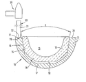
- the figure shows a cross section of a prosthetic Joint socket with an attached impact device.
- a prosthetic socket 10 is from an outer shell 11 and an insert shell 12 inserted therein educated.
- the socket 10 serves to receive a prosthetic joint ball (not shown).
- the outside of the outer shell 11 is spherical, can also have other shapes and that be adapted to the respective purpose and implantation location. It is made of metal, but can also be made of others Materials exist.
- the outer shell 11 faces the opening edge adjacent an inner cone with a cone angle a from 20 ° to.
- the inner cone section 14 extends about half the height of the outer shell 11. Closes in the bottom area of the outer shell 11 the bottom wall 17 on the inner cone section 14 on.
- the insert shell 12 has a spherical recess 13 for receiving the joint ball. On the outside it has an outer cone section 15 with the same cone angle a as the inner cone 14 of the Outer shell 11.
- the effective length of the outer cone 15 is slightly shorter than that of the inner cone 14.
- At the outer cone section 15 closes in the bottom area of the Insert shell 12 on a bottom wall 16, which when inserted Insert shell 12 not the bottom wall 17 of the Touches outer shell 11.
- the bottom walls 16.17 in the Insert shell 12 and the outer shell 11 form one Cavity 18, the insertion of the insert shell 12 in the outer shell 11 excludes.
- the opening edge of the outer shell 11 is as one narrow ring surface 21 formed perpendicular to Longitudinal axis of the socket 10 is arranged.
- a recess 25 is provided on the Annular surface 21 .
- the annular surface 21 can also contain several recesses to the Impact body always at an easily accessible recess to be able to start.
- a chisel-like impact body is used as the impact device 30 31 used, a protuberance at one end 32 which fits into the recess 25.
- a hammer 35 is used for impact pulses, with the on the free end of the striker 30 is struck.
- the insert shell 12 is made of ceramic and the outer shell 11 made of metal, but the shells can each also consist of other materials.
- the inner surface is during their prosthetic use the recess 13 of the insert shell 12 permanent Exposed to wear. Especially with the heavily used ones Hip joints can therefore be replaced worn insert shell 12 sooner or later required his. This exchange is done in situ, i.e. the acetabular prosthesis remains in each bone.
- the removal and replacement of the insert shell is simple, quick and splinter-free.
Landscapes
- Health & Medical Sciences (AREA)
- Orthopedic Medicine & Surgery (AREA)
- Transplantation (AREA)
- Heart & Thoracic Surgery (AREA)
- Life Sciences & Earth Sciences (AREA)
- Oral & Maxillofacial Surgery (AREA)
- Engineering & Computer Science (AREA)
- Biomedical Technology (AREA)
- Veterinary Medicine (AREA)
- Vascular Medicine (AREA)
- Cardiology (AREA)
- Animal Behavior & Ethology (AREA)
- General Health & Medical Sciences (AREA)
- Public Health (AREA)
- Physical Education & Sports Medicine (AREA)
- Prostheses (AREA)
- Helmets And Other Head Coverings (AREA)
Description
Claims (5)
- Prothetische Gelenkpfanne mit einer Außenschale (11), in der mit Klemmsitz eine austauschbare Einsatzschale (12) eingesetzt ist, wobeidie Einsatzschale (12) einen Außenkonus-Abschnitt (15) aufweist, der in einen Innenkonus-Abschnitt (14) der Außenschale (11) eingepaßt ist, so daß zwischen den Abschnitten (14,15) der Außenschale (11) und der eingesetzten Einsatzschale (12) eine haltende Klemmkraft auftritt,
dadurch gekennzeichnet, daßdie Außenschale (11) an ihrem Öffnungsrand (21) mindestens einen Ansatz (25) aufweist, an den eine Schlagvorrichtung (30) unverschiebbar ansetzbar ist. - Prothetische Gelenkpfanne nach Anspruch 1, dadurch gekennzeichnet, daß der Konuswinkel (a) der Konusabschnitte (14,15) der Außenschale (11) und der Einsatzschale (12) gleich ist und zwischen 14° und 22° beträgt.
- Prothetische Gelenkpfanne nach Anspruch 1 oder 2, dadurch gekennzeichnet, daß der Bodenbereich (17) der Außenschale (11) und der Bodenbereich (16) der Einsatzschale (12) einen Hohlraum (18) bilden.
- Prothetische Gelenkpfanne nach einem der Ansprüche 1-3, dadurch gekennzeichnet, daß der Ansatz (25) eine muldenartige Ausnehmung ist, in die eine Ausstülpung (32) der Schlagvorrichtung (30) einsetzbar ist.
- Prothetische Gelenkpfanne nach einem der Ansprüche 1 bis 5, dadurch gekennzeichnet, daß die Außenschale (11) aus Metall und die Innenschale (12) aus Keramik besteht.
Applications Claiming Priority (2)
| Application Number | Priority Date | Filing Date | Title |
|---|---|---|---|
| DE19611248 | 1996-03-22 | ||
| DE19611248A DE19611248A1 (de) | 1996-03-22 | 1996-03-22 | Prothetische Gelenkpfanne |
Publications (3)
| Publication Number | Publication Date |
|---|---|
| EP0796598A2 EP0796598A2 (de) | 1997-09-24 |
| EP0796598A3 EP0796598A3 (de) | 1998-01-14 |
| EP0796598B1 true EP0796598B1 (de) | 2002-07-10 |
Family
ID=7789035
Family Applications (1)
| Application Number | Title | Priority Date | Filing Date |
|---|---|---|---|
| EP97103833A Expired - Lifetime EP0796598B1 (de) | 1996-03-22 | 1997-03-07 | Prothetische Gelenkpfanne |
Country Status (4)
| Country | Link |
|---|---|
| EP (1) | EP0796598B1 (de) |
| AT (1) | ATE220310T1 (de) |
| DE (2) | DE19611248A1 (de) |
| ES (1) | ES2175210T3 (de) |
Families Citing this family (8)
| Publication number | Priority date | Publication date | Assignee | Title |
|---|---|---|---|---|
| DE29703857U1 (de) * | 1997-03-03 | 1997-05-07 | Aesculap Ag, 78532 Tuttlingen | Chirurgisches Instrument |
| DE19813074A1 (de) * | 1998-03-25 | 1999-09-30 | Ceram Tec Ag Innovative Cerami | Klemmsitz-Verbindung zwischen Prothesenkomponenten von Gelenk-Prothesen |
| DE19824328C1 (de) * | 1998-06-02 | 2000-03-09 | Eska Implants Gmbh & Co | Instrument zum Herauslösen eines Inlays aus dem Sockel einer Beckenpfanne eines künstlichen Hüftgelenks |
| DE19904437A1 (de) | 1999-02-04 | 2000-08-10 | Ceramtec Ag | Klemmsitz-Verbindung zwischen Prothesenkomponenten von Gelenk-Prothesen |
| FR2887136B1 (fr) * | 2005-06-17 | 2007-09-07 | C2M Implants | Implant cotiloidien de prothese de hanche |
| AU2011247570B2 (en) * | 2010-04-30 | 2015-09-17 | Ceramtec Gmbh | Increasing the breaking load of ceramic cup inserts for hip joint prostheses by a defined back side collision of the cup insert and acetabular cup |
| JP5965121B2 (ja) * | 2011-09-15 | 2016-08-03 | 京セラメディカル株式会社 | 人工股関節用コンポーネント |
| DE102012207450A1 (de) | 2012-05-04 | 2013-11-07 | Aesculap Ag | Lösungsinstrument |
Family Cites Families (9)
| Publication number | Priority date | Publication date | Assignee | Title |
|---|---|---|---|---|
| AT52179B (de) * | 1908-09-21 | 1912-02-10 | Griesheim Elektron Chem Fab | Verfahren zur Herstellung von Schwefelsäure in Türmen. |
| DE2950536A1 (de) * | 1979-12-15 | 1981-07-02 | Howmedica International, Inc. Zweigniederlassung Kiel, 2300 Kiel | Hueftpfanne |
| DE4335931B4 (de) * | 1993-10-21 | 2006-10-12 | Cerasiv Gmbh Innovatives Keramik-Engineering | Hüftgelenkpfanne |
| DE4337936A1 (de) * | 1993-11-06 | 1995-05-11 | Cerasiv Gmbh | Sphärische Hüftgelenkpfanne |
| DE4402675A1 (de) * | 1993-11-26 | 1995-06-01 | Cerasiv Gmbh | Konische Hüftgelenkpfanne ohne Selbsthemmung |
| CH687436A5 (de) * | 1994-07-28 | 1996-12-13 | Werner Hermann | Pfannenteil einer Hueftgelenks-Prothese. |
| DE9418900U1 (de) * | 1994-11-25 | 1995-01-26 | Mai, Steffen, Dipl.-Ing., 07426 Dörnfeld a d Heide | Prothesenpfanne für eine Hüftgelenk-Endoprothese |
| DE29516473U1 (de) * | 1995-10-17 | 1995-12-07 | KERAMED Medizintechnik GmbH, 07646 Mörsdorf | Künstliche Hüftgelenkpfanne |
| DE29703857U1 (de) * | 1997-03-03 | 1997-05-07 | Aesculap Ag, 78532 Tuttlingen | Chirurgisches Instrument |
-
1996
- 1996-03-22 DE DE19611248A patent/DE19611248A1/de not_active Withdrawn
-
1997
- 1997-03-07 DE DE59707667T patent/DE59707667D1/de not_active Expired - Lifetime
- 1997-03-07 ES ES97103833T patent/ES2175210T3/es not_active Expired - Lifetime
- 1997-03-07 EP EP97103833A patent/EP0796598B1/de not_active Expired - Lifetime
- 1997-03-07 AT AT97103833T patent/ATE220310T1/de not_active IP Right Cessation
Also Published As
| Publication number | Publication date |
|---|---|
| EP0796598A3 (de) | 1998-01-14 |
| EP0796598A2 (de) | 1997-09-24 |
| ATE220310T1 (de) | 2002-07-15 |
| DE19611248A1 (de) | 1997-09-25 |
| ES2175210T3 (es) | 2002-11-16 |
| DE59707667D1 (de) | 2002-08-14 |
Similar Documents
| Publication | Publication Date | Title |
|---|---|---|
| EP1922035B1 (de) | Einsetzinstrument für eine endoprothese mit einem in einem markraum einzusetzenden prothesenschaft | |
| EP0241792B1 (de) | Setz- und Einschlaginstrument für einen Knochennagel | |
| DE69417098T2 (de) | Biologisch abbaubarer medullärer Pfropfen | |
| DE19813328A1 (de) | Einrichtung zur Handhabung von Kugelköpfen von Gelenk-Prothesen | |
| DE2551013B2 (de) | Oberschenkelknocheneinsatz für Hüftgelenkprothesen | |
| EP0619097A1 (de) | Raspel und eine damit kuppelbares Griffteil zum Vorbereiten eines Röhrenknochens für den Einsatz einer Prothese | |
| WO1994026176A1 (de) | Vorrichtung zum austrennen von endoprothesen | |
| DE202006010069U1 (de) | Einsetzinstrument für Gelenkpfannen von Prothesen | |
| DE69514621T2 (de) | Femurschaft für Hüftprothese | |
| CH687436A5 (de) | Pfannenteil einer Hueftgelenks-Prothese. | |
| EP0796598A2 (de) | Prothetische Gelenkpfanne | |
| DE10218801B3 (de) | Set zur Erstellung eines Armierungsimplantates | |
| CH669902A5 (de) | ||
| DE4219411C1 (de) | Einsetzwerkzeug für eine Schraubeneinheit | |
| EP2898860B1 (de) | Hüftgelenk-Endoprothesen-System | |
| DE19708604C1 (de) | Chirurgisches Instrument | |
| DE9412408U1 (de) | Hüftstiel für ein künstliches Hüftgelenk mit Kragen | |
| DE102006032534B4 (de) | Osteotom | |
| DE4243444C2 (de) | Raspel zur Vorbereitung einer Knochenöffnung | |
| DE3902775A1 (de) | Oberschenkelgelenk-prothese | |
| DE19611249A1 (de) | Kombination aus einer Gelenkprothese und einem Ausziehwerkzeug | |
| DE10031271B4 (de) | Hüftpfannenimplantationsgerät | |
| DE29824993U1 (de) | Einrichtung zur Handhabung von Kugelköpfen von Gelenk-Prothesen | |
| DE19916025A1 (de) | Vorrichtung zur Aufnahme von länglichen Werkzeugen in einer bestimmten Aufnahmeposition, insbesondere zur Aufnahme von Wurzelkanalfeilen | |
| WO2007137688A1 (de) | Chirurgischer extraktor |
Legal Events
| Date | Code | Title | Description |
|---|---|---|---|
| PUAI | Public reference made under article 153(3) epc to a published international application that has entered the european phase |
Free format text: ORIGINAL CODE: 0009012 |
|
| AK | Designated contracting states |
Kind code of ref document: A2 Designated state(s): AT CH DE ES FR GB IT LI |
|
| PUAL | Search report despatched |
Free format text: ORIGINAL CODE: 0009013 |
|
| AK | Designated contracting states |
Kind code of ref document: A3 Designated state(s): AT CH DE ES FR GB IT LI |
|
| 17P | Request for examination filed |
Effective date: 19980620 |
|
| GRAG | Despatch of communication of intention to grant |
Free format text: ORIGINAL CODE: EPIDOS AGRA |
|
| 17Q | First examination report despatched |
Effective date: 20011008 |
|
| GRAG | Despatch of communication of intention to grant |
Free format text: ORIGINAL CODE: EPIDOS AGRA |
|
| GRAH | Despatch of communication of intention to grant a patent |
Free format text: ORIGINAL CODE: EPIDOS IGRA |
|
| GRAH | Despatch of communication of intention to grant a patent |
Free format text: ORIGINAL CODE: EPIDOS IGRA |
|
| GRAA | (expected) grant |
Free format text: ORIGINAL CODE: 0009210 |
|
| AK | Designated contracting states |
Kind code of ref document: B1 Designated state(s): AT CH DE ES FR GB IT LI |
|
| REF | Corresponds to: |
Ref document number: 220310 Country of ref document: AT Date of ref document: 20020715 Kind code of ref document: T |
|
| REG | Reference to a national code |
Ref country code: GB Ref legal event code: FG4D Free format text: NOT ENGLISH |
|
| REG | Reference to a national code |
Ref country code: CH Ref legal event code: EP |
|
| REG | Reference to a national code |
Ref country code: CH Ref legal event code: NV Representative=s name: ISLER & PEDRAZZINI AG |
|
| GBT | Gb: translation of ep patent filed (gb section 77(6)(a)/1977) |
Effective date: 20020721 |
|
| REF | Corresponds to: |
Ref document number: 59707667 Country of ref document: DE Date of ref document: 20020814 |
|
| REG | Reference to a national code |
Ref country code: ES Ref legal event code: FG2A Ref document number: 2175210 Country of ref document: ES Kind code of ref document: T3 |
|
| ET | Fr: translation filed | ||
| PLBE | No opposition filed within time limit |
Free format text: ORIGINAL CODE: 0009261 |
|
| STAA | Information on the status of an ep patent application or granted ep patent |
Free format text: STATUS: NO OPPOSITION FILED WITHIN TIME LIMIT |
|
| 26N | No opposition filed |
Effective date: 20030411 |
|
| REG | Reference to a national code |
Ref country code: CH Ref legal event code: PCAR Free format text: ISLER & PEDRAZZINI AG;POSTFACH 1772;8027 ZUERICH (CH) |
|
| PGFP | Annual fee paid to national office [announced via postgrant information from national office to epo] |
Ref country code: ES Payment date: 20100324 Year of fee payment: 14 Ref country code: CH Payment date: 20100325 Year of fee payment: 14 |
|
| PGFP | Annual fee paid to national office [announced via postgrant information from national office to epo] |
Ref country code: IT Payment date: 20100324 Year of fee payment: 14 Ref country code: FR Payment date: 20100402 Year of fee payment: 14 |
|
| PGFP | Annual fee paid to national office [announced via postgrant information from national office to epo] |
Ref country code: GB Payment date: 20100322 Year of fee payment: 14 Ref country code: AT Payment date: 20100311 Year of fee payment: 14 |
|
| PGFP | Annual fee paid to national office [announced via postgrant information from national office to epo] |
Ref country code: DE Payment date: 20100519 Year of fee payment: 14 |
|
| REG | Reference to a national code |
Ref country code: CH Ref legal event code: PL |
|
| GBPC | Gb: european patent ceased through non-payment of renewal fee |
Effective date: 20110307 |
|
| PG25 | Lapsed in a contracting state [announced via postgrant information from national office to epo] |
Ref country code: AT Free format text: LAPSE BECAUSE OF NON-PAYMENT OF DUE FEES Effective date: 20110307 |
|
| REG | Reference to a national code |
Ref country code: FR Ref legal event code: ST Effective date: 20111130 |
|
| PG25 | Lapsed in a contracting state [announced via postgrant information from national office to epo] |
Ref country code: FR Free format text: LAPSE BECAUSE OF NON-PAYMENT OF DUE FEES Effective date: 20110331 Ref country code: DE Free format text: LAPSE BECAUSE OF NON-PAYMENT OF DUE FEES Effective date: 20111001 Ref country code: CH Free format text: LAPSE BECAUSE OF NON-PAYMENT OF DUE FEES Effective date: 20110331 Ref country code: LI Free format text: LAPSE BECAUSE OF NON-PAYMENT OF DUE FEES Effective date: 20110331 |
|
| REG | Reference to a national code |
Ref country code: DE Ref legal event code: R119 Ref document number: 59707667 Country of ref document: DE Effective date: 20111001 |
|
| PG25 | Lapsed in a contracting state [announced via postgrant information from national office to epo] |
Ref country code: IT Free format text: LAPSE BECAUSE OF NON-PAYMENT OF DUE FEES Effective date: 20110307 Ref country code: GB Free format text: LAPSE BECAUSE OF NON-PAYMENT OF DUE FEES Effective date: 20110307 |
|
| REG | Reference to a national code |
Ref country code: ES Ref legal event code: FD2A Effective date: 20120423 |
|
| PG25 | Lapsed in a contracting state [announced via postgrant information from national office to epo] |
Ref country code: ES Free format text: LAPSE BECAUSE OF NON-PAYMENT OF DUE FEES Effective date: 20110308 |