EP0796680A1 - Perfectionnement pour procédé de réalisation de goujons ou tirants filetés - Google Patents
Perfectionnement pour procédé de réalisation de goujons ou tirants filetés Download PDFInfo
- Publication number
- EP0796680A1 EP0796680A1 EP97410029A EP97410029A EP0796680A1 EP 0796680 A1 EP0796680 A1 EP 0796680A1 EP 97410029 A EP97410029 A EP 97410029A EP 97410029 A EP97410029 A EP 97410029A EP 0796680 A1 EP0796680 A1 EP 0796680A1
- Authority
- EP
- European Patent Office
- Prior art keywords
- rod
- groove
- rolling
- thread
- threaded
- Prior art date
- Legal status (The legal status is an assumption and is not a legal conclusion. Google has not performed a legal analysis and makes no representation as to the accuracy of the status listed.)
- Granted
Links
- 238000000034 method Methods 0.000 title claims abstract description 45
- 238000004519 manufacturing process Methods 0.000 title claims description 9
- 238000005096 rolling process Methods 0.000 claims description 55
- 239000000463 material Substances 0.000 claims description 10
- 230000000903 blocking effect Effects 0.000 claims description 4
- 230000000630 rising effect Effects 0.000 claims 1
- 238000002513 implantation Methods 0.000 description 2
- 230000035515 penetration Effects 0.000 description 2
- 230000015572 biosynthetic process Effects 0.000 description 1
- 230000000295 complement effect Effects 0.000 description 1
- 238000005520 cutting process Methods 0.000 description 1
- 238000010586 diagram Methods 0.000 description 1
- 239000007943 implant Substances 0.000 description 1
- 230000003313 weakening effect Effects 0.000 description 1
Images


Classifications
-
- B—PERFORMING OPERATIONS; TRANSPORTING
- B21—MECHANICAL METAL-WORKING WITHOUT ESSENTIALLY REMOVING MATERIAL; PUNCHING METAL
- B21H—MAKING PARTICULAR METAL OBJECTS BY ROLLING, e.g. SCREWS, WHEELS, RINGS, BARRELS, BALLS
- B21H3/00—Making helical bodies or bodies having parts of helical shape
- B21H3/02—Making helical bodies or bodies having parts of helical shape external screw-threads ; Making dies for thread rolling
- B21H3/022—Making helical bodies or bodies having parts of helical shape external screw-threads ; Making dies for thread rolling combined with rolling splines, ribs, grooves or the like, e.g. using compound dies
-
- B—PERFORMING OPERATIONS; TRANSPORTING
- B21—MECHANICAL METAL-WORKING WITHOUT ESSENTIALLY REMOVING MATERIAL; PUNCHING METAL
- B21H—MAKING PARTICULAR METAL OBJECTS BY ROLLING, e.g. SCREWS, WHEELS, RINGS, BARRELS, BALLS
- B21H3/00—Making helical bodies or bodies having parts of helical shape
- B21H3/02—Making helical bodies or bodies having parts of helical shape external screw-threads ; Making dies for thread rolling
- B21H3/04—Making by means of profiled-rolls or die rolls
-
- B—PERFORMING OPERATIONS; TRANSPORTING
- B21—MECHANICAL METAL-WORKING WITHOUT ESSENTIALLY REMOVING MATERIAL; PUNCHING METAL
- B21H—MAKING PARTICULAR METAL OBJECTS BY ROLLING, e.g. SCREWS, WHEELS, RINGS, BARRELS, BALLS
- B21H7/00—Making articles not provided for in the preceding groups, e.g. agricultural tools, dinner forks, knives, spoons
- B21H7/18—Making articles not provided for in the preceding groups, e.g. agricultural tools, dinner forks, knives, spoons grooved pins; Rolling grooves, e.g. oil grooves, in articles
- B21H7/187—Rolling helical or rectilinear grooves
Definitions
- the present invention relates to a process for obtaining by deformation of a threaded rod provided with a locking groove, the device intended to implement said method as well as the threaded rod obtained by this method.
- the methods of threading by deformation consist in performing a threading by plastically deforming the envelope or external surface of a cylindrical rod. It is possible during this plastic deformation to obtain a diameter at the top of the thread greater than the initial pitch diameter of said rod, itself greater than the diameter at the bottom of the thread, the material being displaced from the bottom of the threads to form the top of the threads.
- a tie rod or a so-called stud with reduced rod the diameter of the non-threaded part being equal to the diameter on the side of the thread.
- Such threaded rods of the stud or pulling type pose a major drawback when tightening, such a stud or pulling with reduced rod thus tends to implant themselves at random length before being blocked.
- tie rods or studs of the normal rod type that is to say tie rods or studs whose diameter of the smooth part is equal to or greater than the diameter in top of thread of the threaded part.
- the manufacturing process requires that a reduction in diameter of the part intended to be deformed for the production of the thread be made before deformation.
- the present invention consists in making an annular groove for blocking by deformation.
- the improvement provided by the present invention therefore proposes to allow the threading and the annular groove to be blocked by deformation, simultaneously, in order to avoid reworking of the part, causing a loss of time which, when production in high quantity of this type of studs or tie rods, can become very important.
- the method for producing a rod comprising at least one thread is characterized in that it consists in producing the thread and an annular groove for blocking by deformation.
- the thread and the annular locking groove are produced simultaneously.
- said method is a method of rolling the threads and it consists in producing said annular locking groove, so that it is positioned between the thread of the rod and its non-threaded part.
- the rolling tool intended to implement the method is characterized in that it comprises at least one wheel provided at one of its ends with a grooving rolling disc, said grooving rolling disc having a projection rolling circular with a rounded shape at the top.
- the threaded rods, tie rods or studs, obtained by the process have a diameter measured at the bottom of the groove, greater than the diameter measured at the bottom of the threads.
- the diameter at the bottom of the groove of the locking groove is greater than the diameter at the bottom of the thread of the threaded part.
- two material lifts are located on either side of the locking groove, the respective diameters of said lifts of material being less than the diameter at the top of the thread of the threaded part.
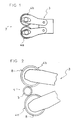
- Figures 1 and 2 show a rolling tool allowing the implementation of the method as well as the diagram of rolling threads by such a tool.
- Figure 1 shows a rolling head or laminator seen in profile.
- Figure 2 shows the rolling of the threads by the two knobs of said head.
- Figures 3 and 4 relate to the wheel of a rolling tool, intended to implement the method according to the invention.
- Figure 3 shows a wheel in longitudinal section.
- FIG. 4 represents a detail of FIG. 1 concerning the part of the tool intended to produce the annular blocking groove.
- Figures 5, 6 and 7 relate to a threaded rod of the stud type obtained by the method according to the invention.
- Figure 5 is an example of a stud with a reduced rod, the ends of which are chamfered.
- Figure 6 is another stud with reduced rod whose ends are rough rolling.
- FIG. 7 shows in detail the annular groove for locking the stud in longitudinal section.
- the improvement of the method for producing a threaded rod of the stud or pulling type consists in carrying out by deformation on said threaded rod (1) an annular locking groove (2).
- said annular locking groove (2) is produced simultaneously with the threading of the threaded rod (1) by deformation according to a method of rolling the threads.
- This rolling method can advantageously be according to the preferred embodiment of the tangential rolling or radial rolling type thanks to a rolling head (3) comprising at least two rolling wheels (4a, 4b), as illustrated in FIGS. 1 and 2.
- a rolling head (3) comprising at least two rolling wheels (4a, 4b), as illustrated in FIGS. 1 and 2.
- it can also be of the type with three or more knobs or planetary (a knurling turning in front of a fixed concave sector) or with flat dies, without thereby departing from the scope of the invention.
- the method therefore consists in producing by rolling on a rod at least one thread (5) and an annular locking groove (2), so that said groove (2) is positioned between the thread (5) and the part of unthreaded rod (6).
- Said annular locking groove (2) can advantageously be produced according to the preferred embodiment, so that the diameter at the bottom of the groove D1 is greater than the diameter at the bottom of the thread D2, as illustrated in FIG. 5 and FIG. 7, in order to avoid the possible rupture problems caused by the production of a circular groove and therefore of a critical section for the resistance to longitudinal traction perpendicular to said section.
- it consists in producing an annular locking groove (2) whose width measured at its top is greater than the pitch of the adjacent thread (5) produced by said rolling method.
- the method advantageously consists in making the thread (5) and the annular locking groove (2) on a rod (1), so as to obtain a stud, a tie rod or a threaded rod, called a rod reduced, that is to say the diameter D3 of the non-threaded portion (6) is substantially equal to the diameter flank D8.
- the device for implementing the method according to the invention is composed of a rolling tool (7) which can be of the flat die type, planetary or rolling heads (3) with rollers (4).
- said dies are provided with a longitudinal projection intended to obtain the annular groove, said projection having an angle (not zero) with the oblique penetration projections intended to obtain the thread.
- the rolling tool is of the planetary type and comprises a wheel equipped with a flange or throat rolling disc allowing an annular locking groove (2) to be made during the rotation of said wheel (4 ) in front of a fixed concave sector.
- the rolling tool (7) intended to be used during the preferred embodiment of the method is a tool having at least two knurling wheels (4a, 4b) mounted on a rolling head (3), as illustrated in FIG. 1, said tool working underwater, that is to say during a rolling process of the radial or tangential type.
- Said tool can, for example, include three or more knobs (4), without going beyond the ambit of the invention.
- the rollers (4) of the rolling head (3) intended to implement the preferred mode of the process are cylindrical in shape and have along their length an external rolling thread (8) intended to produce the thread (5) of the rod (1) by causing formation during rolling of said thread (5) by deformation of the surface of the cylindrical blank of rod (1), deformation due to the penetration of the threads of said external rolling thread (8) in said area.
- the knurls (4) have at their ends (10a, 10b), in a manner known per se, a chamfer (11) an angle or a radiated entry allowing the release of the deformed material during rolling at the start and at the end. of fillet.
- knobs (4) are provided with a coaxial flange or throat rolling disc (12) fixed at one of their ends (10a, 10b), said end (10b) corresponding to that which, during rolling process will allow the positioning of the annular locking groove (2) between the threaded part (5) and the non-threaded part (6) of the rod (1).
- Said groove rolling disc (12) is of diameter D4 less than the diameter D5 measured at the bottom of the external rolling thread (8) of the thumbwheel (4).
- the external diameter D6 of the circular rolling projection (13) is less than the diameter D7 measured at the top of the thread of the external rolling thread (8) of the thumbwheel (4), as illustrated. Figure 4.
- the width of said circular rolling projection (13) taken at its base, that is to say at the diameter D4 must be greater than the pitch of the external rolling thread (8) and can advantageously be equal to one and a half times this step.
- the groove rolling disc (12) is therefore fixed to the wheel (4), as illustrated in FIGS.
- the diameter of the end of the chamfer (11) of the wheel (4) can advantageously be equal to the diameter D4 of the disc (12) and the rolling projection (13) can be very slightly offset from the end of the disc rolling (12) intended to be fixed to the wheel (4), so as to obtain a clean end of thread (5) of the threaded rod (1) in front of the annular locking groove (2), as well as the rise of material (16a) between the groove (2) and the thread due to the deformation produced during the production of said groove.
- the threaded rod (1) obtained by the method according to the invention through the use of an implementation device of the type described above therefore comprises at least one threaded part (5) separated from a non-threaded part (6 ) by an annular locking groove (2).
- It can be of the pin with reduced rod type, as illustrated in FIGS. 5, 6, 7, and have two threaded parts (5a, 5b), surrounding a non-threaded part (6) whose diameter is equal to the diameter on the side of thread of said threaded portions (5a, 5b).
- Said threaded parts (5a, 5b) can be of different length
- the annular locking groove (2) is positioned between one of said threaded parts (5a) generally the shortest called the side of implantation of the stud, and the non-part threaded (6).
- a stud having two annular locking grooves (2) one at each end of the central unthreaded part (6), without thereby departing from the scope of the invention.
- the ends of the threaded rods (1), studs, tie rods or threaded ends obtained by the process may be either chamfered, roughly rolled, curved or with a flat end, or of any other possible type.
- the shape of the threads can be diverse: triangular or trapezoidal, for example.
- the rod, stud or tie rod, threaded (1) according to the rolling method described above therefore has at least one annular locking groove (2) whose diameter at the bottom of the groove D1 is greater than the diameter at the bottom of the thread D2 and of width greater than the pitch of its threaded part, advantageously equal to one and a half times the value of the pitch.
- the bottom (15) of the annular locking groove (2) is rounded so as to reduce the risks of rupture in traction at the level of said annular groove (2).
- the diameter D9 of the material lift (16a) produced during rolling and located between the groove (2) and the threaded part (5) is less than the diameter at the top of the thread D10 of said threaded part.
- the rolling of the locking groove (2) also causes a material rise (16b) of diameter D11 between the groove (2) and the non-threaded part (6).
- the diameter D11 of said material rise (16b) is less than the diameter at the top of the thread D10 and is advantageously substantially equal to the diameter D9 of the other rise (16a).
- such a locking groove (2) can be obtained by the method described above whatever the specific characteristics of the threaded rod such as the nominal diameter, the pitch of the thread, the profile of the thread or the tolerance.
Landscapes
- Engineering & Computer Science (AREA)
- Mechanical Engineering (AREA)
- Forging (AREA)
- Extrusion Moulding Of Plastics Or The Like (AREA)
- Mutual Connection Of Rods And Tubes (AREA)
- Orthopedics, Nursing, And Contraception (AREA)
Abstract
Description
- La présente invention concerne un procédé d'obtention par déformation d'une tige filetée munie d'une gorge de blocage, le dispositif destiné à mettre en oeuvre ledit procédé ainsi que la tige filetée obtenue par ce procédé.
- Les procédés de filetage par déformation consistent à effectuer un filetage en déformant plastiquement l'enveloppe ou surface externe d'une tige cylindrique. On peut lors de cette déformation plastique obtenir un diamètre en sommet de filet supérieur au diamètre primitif initial de ladite tige, lui-même supérieur au diamètre en fond de filet, la matière étant déplacée du fond des filets pour former le sommet des filets. On obtient alors par un tel procédé un tirant ou un goujon dit à tige réduite, le diamètre de la partie non filetée étant égal au diamètre à flanc de filet. De telles tiges filetées du type goujon ou tirant, lors de leur implantation, posent un inconvénient majeur lors du serrage, un tel goujon ou tirant à tige réduite a ainsi tendance à s'implanter selon une longueur aléatoire avant de subir son blocage.
- Afin d'éviter un tel inconvénient, il est possible de réaliser des tirants ou des goujons du type à tige normale, c'est-à-dire des tirants ou des goujons dont le diamètre de la partie lisse est égal ou supérieur au diamètre en sommet de filet de la partie filetée. Toutefois, le processus de fabrication nécessite que soit réalisée avant déformation une diminution de diamètre de la partie destinée à être déformée pour la réalisation du filetage.
- C'est afin de remédier à cet inconvénient que la présente invention consiste à effectuer une gorge annulaire de blocage par déformation.
- De plus, les procédés de roulage actuels ne prévoient pas la possibilité d'effectuer une telle gorge lors du filetage de la tige et contraignent ainsi l'utilisateur à faire réaliser celle-ci par taillage ou autre procédé, nécessitant de ce fait ce qu'il est convenu d'appeler une reprise de la pièce.
- Le perfectionnement apporté par la présente invention se propose donc de permettre l'obtention du filetage et de la gorge annulaire de blocage par déformation, de manière simultanée afin d'éviter une reprise de la pièce, occasionnant une perte de temps qui, lors de la production en haute quantité de ce type de goujons ou tirants, peut devenir très importante.
- Ainsi, selon l'invention, le procédé de réalisation d'une tige comprenant au moins un filetage est caractérisé en ce qu'il consiste à réaliser le filetage et une gorge annulaire de blocage par déformation.
- Selon une caractéristique complémentaire, le filetage et la gorge annulaire de blocage sont réalisés de manière simultanée.
- Selon une autre caractéristique, ledit procédé est un procédé de roulage des filets et il consiste à réaliser ladite gorge annulaire de blocage, de manière à ce qu'elle soit positionnée entre le filetage de la tige et sa partie non filetée.
- L'outil de roulage destiné à mettre en oeuvre le procédé est caractérisé en ce qu'il comporte au moins une molette munie à l'une de ses extrémités d'un disque de roulage de gorge, ledit disque de roulage de gorge possédant une saillie circulaire de roulage de forme arrondie au sommet.
- Selon une caractéristique complémentaire, les tiges filetées, tirants ou goujons, obtenus par le procédé, possèdent un diamètre mesuré en fond de gorge, supérieur au diamètre mesuré en fond de filets.
- Selon une autre caractéristique des tige, tirants ou goujons, filetée obtenue par le procédé, le diamètre en fond de gorge de la gorge de blocage est supérieur au diamètre en fond de filet de la partie filetée.
- De plus, deux remontées de matière sont situées de part et d'autre de la gorge de blocage, les diamètres respectifs desdites remontées de matière étant inférieurs au diamètre en sommet de filet de la partie filetée.
- D'autres caractéristiques et avantages de l'invention se dégageront de la description qui va suivre en regard des dessins annexés qui ne sont donnés qu'à titre d'exemples non limitatifs.
- Les figures 1 et 2 représentent un outil de roulage permettant la mise en oeuvre du procédé ainsi que la schématisation du roulage des filets par un tel outil.
- La figure 1 représente une tête de roulage ou lamineur vue de profil.
- La figure 2 représente le roulage des filets par les deux molettes de ladite tête.
- Les figures 3 et 4 concernent la molette d'un outil de roulage, destinée à mettre en oeuvre le procédé selon l'invention.
- La figure 3 représente une molette en coupe longitudinale.
- La figure 4 représente un détail de la figure 1 concemant la partie de l'outil destinée à réaliser la gorge annulaire de blocage.
- Les figures 5, 6 et 7 concernent une tige filetée du type goujon obtenue par le procédé selon l'invention.
- La figure 5 est un exemple de goujon à tige réduite dont les extrémités sont chanfreinées.
- La figure 6 est un autre goujon à tige réduite dont les extrémités sont brutes de roulage.
- La figure 7 représente en détail la gorge annulaire de blocage du goujon en coupe longitudinale.
- Ainsi, le perfectionnement du procédé de réalisation d'une tige filetée du type goujons ou tirants consiste à effectuer par déformation sur ladite tige filetée (1) une gorge annulaire de blocage (2).
- Selon le mode préféré de mise en oeuvre du procédé, ladite gorge annulaire de blocage (2) est réalisée simultanément au filetage de la tige filetée (1) par déformation selon un procédé de roulage des filets. Ce procédé de roulage peut être avantageusement selon le mode de mise en oeuvre préféré du type roulage tangentiel ou roulage radial grâce à une tête de roulage (3) comprenant au moins deux molettes (4a, 4b) de roulage, tel qu'illustré figures 1 et 2. Cependant, il peut également être du type à trois molettes ou plus ou planétaire (une molette tournant devant un secteur concave fixe) ou à matrices planes, sans pour autant sortir du cadre de l'invention.
- Le procédé consiste donc à réaliser par roulage sur une tige au moins un filetage (5) et une gorge annulaire de blocage (2), de façon à ce que ladite gorge (2) soit positionnée entre le filetage (5) et la partie de tige non filetée (6). Ladite gorge annulaire de blocage (2) peut avantageusement être réalisée selon le mode de mise en oeuvre préféré, de manière à ce que le diamètre en fond de gorge D1 soit supérieur au diamètre en fond de filet D2, tel qu'illustré figure 5 et figure 7, afin d'éviter les problèmes de rupture éventuels occasionnés par la réalisation d'une gorge circulaire et donc d'une section critique pour la résistance à la traction longitudinale perpendiculaire à ladite section. Selon une caractéristique complémentaire dudit procédé, celui-ci consiste à réaliser une gorge annulaire de blocage (2) dont la largeur mesurée à son sommet est supérieure au pas du filetage (5) adjacent réalisé par ledit procédé de roulage. Elle peut avantageusement, selon le mode de mise en oeuvre préféré, être égale à une fois et demie la valeur du pas. De plus, le procédé consiste avantageusement à effectuer le filetage (5) et la gorge annulaire de blocage (2) sur une tige (1), de manière à obtenir un goujon, un tirant ou une tige filetée, dit(e) à tige réduite, c'est-à-dire dont le diamètre D3 de la portion non filetée (6) est égal sensiblement au diamètre à flanc de filet D8.
- Le dispositif de mise en oeuvre du procédé selon l'invention est composé d'un outil de roulage (7) pouvant être du type matrices planes, planétaires ou têtes de roulage (3) à molettes (4). Selon la variante dudit procédé consistant à utiliser des matrices planes à mouvement alternatif, lesdites matrices sont pourvues d'une saillie longitudinale destinée à obtenir la gorge annulaire, ladite saillie présentant un angle (non nul) avec les saillies obliques de pénétration destinées à obtenir le filetage.
- Selon une autre variante, l'outil de roulage est du type planétaire et comporte une molette équipée d'un flasque ou disque de roulage de gorge permettant d'effectuer une gorge annulaire de blocage (2) lors de la rotation de ladite molette (4) devant un secteur concave fixe.
- L'outil de roulage (7) destiné à être utilisé lors du mode de mise en oeuvre préféré du procédé est un outil possédant au moins deux molettes (4a, 4b) montées sur une tête de roulage (3), tel qu'illustré figure 1, ledit outil travaillant en plongée, c'est-à-dire lors d'un procédé de roulage de type radial ou tangentiel. Ledit outil peut, par exemple, comporter trois molettes (4) ou plus, sans pour autant sortir du cadre de l'invention.
- Les molettes (4) de la tête à rouler (3) destinées à mettre en oeuvre le mode préféré du procédé sont de formes cylindriques et comportent sur leur longueur un filetage externe de roulage (8) destiné à réaliser le filetage (5) de la tige (1) en provoquant la formation lors du roulage dudit filetage (5) par déformation de la surface de l'ébauche cylindrique de la tige (1), déformation due à la pénétration des filets dudit filetage externe de roulage (8) dans ladite surface.
- En outre, les molettes (4) possèdent à leurs extrémités (10a, 10b), de manière connue en soi, un chanfrein (11) un angle ou une entrée rayonnée permettant le dégagement de la matière déformée lors du roulage en début et en fin de filet.
- De plus, lesdites molettes (4) sont munies d'un flasque ou disque de roulage de gorge (12) coaxial fixé à l'une de leurs extrémités (10a, 10b), ladite extrémité (10b) correspondant à celle qui, lors du procédé de roulage permettra le positionnement de la gorge annulaire de blocage (2) entre la partie filetée (5) et la partie non filetée (6) de la tige (1). Ledit disque de roulage de gorge (12) est de diamètre D4 inférieur au diamètre D5 mesuré à fond de filet du filetage externe de roulage (8) de la molette (4). Il possède à son extrémité destinée à être contiguë à la molette (4) une saillie circulaire de roulage (13) dont le sommet (14) est avantageusement arrondi de manière à ce que la gorge annulaire de blocage (2) obtenue grâce à cette saillie (12) possède un fond (15) arrondi, ceci afin d'éviter d'affaiblir la résistance à la traction de la tige (1) à l'endroit de la section transversale contenant ladite gorge (2).
- De même, pour des raisons similaires, le diamètre externe D6 de la saillie circulaire de roulage (13) est inférieur au diamètre D7 mesuré au sommet de filet du filetage externe de roulage (8) de la molette (4), tel qu'illustré figure 4. De plus, la largeur de ladite saillie circulaire de roulage (13) prise à sa base c'est-à-dire au niveau du diamètre D4 doit être supérieure au pas du filetage externe de roulage (8) et peut avantageusement être égale à une fois et demie ce pas. Le disque de roulage de gorge (12) est donc fixé à la molette (4), tel qu'illustré figures 3 et 4 ; le diamètre de l'extrémité du chanfrein (11) de la molette (4) pouvant avantageusement être égal au diamètre D4 du disque (12) et la saillie de roulage (13) peut être très légèrement décalée par rapport à l'extrémité du disque de roulage (12) destinée à être fixée à la molette (4), de manière à permettre l'obtention d'une fin de filetage (5) nette de la tige filetée (1) devant la gorge annulaire de blocage (2), ainsi que la remontée de matière (16a) entre la gorge (2) et le filetage due à la déformation produite lors de la réalisation de ladite gorge.
- La tige filetée (1) obtenue par le procédé selon l'invention grâce à l'utilisation d'un dispositif de mise en oeuvre du type décrit précédemment comprend donc au moins une partie filetée (5) séparée d'une partie non filetée (6) par une gorge annulaire de blocage (2). Elle peut être du type goujon à tige réduite, tel qu'illustré figures 5, 6, 7, et posséder deux parties filetées (5a, 5b), entourant une partie non filetée (6) dont le diamètre est égal au diamètre à flanc de filet desdites parties filetées (5a, 5b). Lesdites parties filetées (5a, 5b) pouvant être de longueur différente, la gorge annulaire de blocage (2) est positionnée entre l'une desdites parties filetées (5a) généralement la plus courte appelée côté d'implantation du goujon, et la partie non filetée (6).
- De plus, il peut être avantageux de réaliser un goujon à tige réduite (1) dont la partie centrale non filetée (6) est de très faible longueur, la partie filetée (5b) s'arrêtant à proximité de la gorge de blocage (2), les filets (5b) servant alors de guides pour la ou les pièce(s) à maintenir.
- De plus, on peut également réaliser, grâce au procédé, un goujon possédant deux gorges annulaires de blocage (2), une à chaque extrémité de la partie non filetée (6) centrale, sans pour autant sortir du champ de l'invention. Les extrémités des tiges filetées (1), goujons, tirants ou bouts filetés obtenues par le procédé peuvent être soit chanfreinées, soit brutes de roulage, soit bombées ou à bout plat, ou de tout autre type possible. De même, la forme des filets peut être diverse : triangulaire ou trapézoïdale, par exemple.
- La tige, goujon ou tirant, filetée (1) selon le procédé de roulage décrit précédemment possède donc au moins une gorge annulaire de blocage (2) dont le diamètre en fond de gorge D1 est supérieur au diamètre en fond de filet D2 et de largeur supérieure au pas de sa partie filetée, avantageusement égale à une fois et demie la valeur du pas. Le fond (15) de la gorge annulaire de blocage (2) est arrondi de manière à diminuer les risques de rupture en traction au niveau de ladite gorge annulaire (2).
- Par ailleurs, il est important de noter que le diamètre D9 de la remontée de matière (16a) produite lors du roulage et située entre la gorge (2) et la partie filetée (5) est inférieur au diamètre en sommet de filet D10 de ladite partie filetée. De plus, le roulage de la gorge de blocage (2) provoque également une remontée de matière (16b) de diamètre D11 entre la gorge (2) et la partie non filetée (6). Le diamètre D11 de ladite remontée de matière (16b) est inférieur au diamètre en sommet de filet D10 et est avantageusement sensiblement égal au diamètre D9 de l'autre remontée (16a). Selon l'invention, une telle gorge de blocage (2) peut être obtenu par le procédé décrit précédemment quelque soit les caractéristiques propres de la tige filetée telles que le diamètre nominal, le pas du filetage, le profil du filet ou la tolérance.
- Il va de soi que le procédé décrit et illustré dans le cas d'un roulage de filet effectué par une tête à rouler du type lamineur n'exclut aucunement de la protection des procédés équivalents utilisant d'autres types de machines à rouler permettant les réalisations de filetage et de gorge de blocage par déformation.
- Bien entendu, l'invention n'est pas limitée aux modes de réalisation décrits et représentés à titre d'exemples, mais elle comprend aussi tous les équivalents techniques ainsi que leurs combinaisons.
Claims (10)
- Procédé de réalisation d'une tige (1) comprenant au moins un filetage (5), caractérisé en ce qu'il consiste à réaliser le filetage (5) et une gorge annulaire de blocage (2) par déformation.
- Procédé selon la revendication 1, caractérisé en ce que le filetage (5) et la gorge annulaire de blocage (2) sont réalisés de manière simultanée.
- Procédé selon l'une quelconque des revendications précédentes, caractérisé en ce que ledit procédé est un procédé de roulage des filets.
- Procédé selon l'une quelconque des revendications précédentes, caractérisé en ce qu'il consiste à réaliser ladite gorge annulaire de blocage (2), de manière à ce qu'elle soit positionnée entre le filetage (5) de la tige (1) et sa partie non filetée (6).
- Outil de roulage (7) destiné à mettre en oeuvre le procédé selon la revendication 3, et l'une quelconque des revendications précédentes, caractérisé en ce qu'il comporte au moins une molette (4) munie à l'une de ses extrémités (10a, 10b) d'un disque de roulage de gorge (12).
- Outil (7) selon la revendication 5, caractérisé en ce que ledit disque de roulage de gorge (12) possède une saillie circulaire de roulage (13) de forme arrondie à son sommet (14).
- Tige, tirant ou goujon, filetée (1) obtenue par le procédé selon l'une quelconque des revendications 1 à 4, caractérisée en ce que le diamètre mesuré en fond de gorge est supérieur au diamètre mesuré en fond de filets.
- Goujon à tige réduite obtenu par le procédé selon l'une quelconque des revendications 1 à 4, caractérisé en ce que la gorge annulaire de blocage (2) est située entre la partie filetée (5a, 5b) et la partie centrale non filetée (6).
- Tige, tirant ou goujon, filetée (1) obtenue par le procédé selon l'une quelconque des revendications 1 à 4, caractérisé en ce que le diamètre en fond de gorge D1 de la gorge de blocage (2) est supérieur au diamètre en fond de filet D2 de la partie filetée (5, 5a, 5b).
- Tige, tirant ou goujon, filetée (1) obtenue par le procédé selon l'une quelconque des revendications 1 à 4, caractérisé en ce que deux remontées de matière (16a, 16b) sont situées de part et d'autre de la gorge de blocage (2), les diamètres respectifs D9 et D11 desdites remontées de matière étant inférieurs au diamètre en sommet de filet D10 de la partie filetée (5, 5a, 5b).
Applications Claiming Priority (2)
| Application Number | Priority Date | Filing Date | Title |
|---|---|---|---|
| FR9603770 | 1996-03-19 | ||
| FR9603770A FR2746331B1 (fr) | 1996-03-19 | 1996-03-19 | Perfectionnement pour procede de realisation de goujons ou tirants filetes |
Publications (2)
| Publication Number | Publication Date |
|---|---|
| EP0796680A1 true EP0796680A1 (fr) | 1997-09-24 |
| EP0796680B1 EP0796680B1 (fr) | 2002-10-02 |
Family
ID=9490569
Family Applications (1)
| Application Number | Title | Priority Date | Filing Date |
|---|---|---|---|
| EP97410029A Expired - Lifetime EP0796680B1 (fr) | 1996-03-19 | 1997-03-11 | Perfectionnement pour procédé de réalisation de goujons ou tirants filetés |
Country Status (7)
| Country | Link |
|---|---|
| EP (1) | EP0796680B1 (fr) |
| AT (1) | ATE225220T1 (fr) |
| DE (1) | DE69715944T2 (fr) |
| DK (1) | DK0796680T3 (fr) |
| ES (1) | ES2184975T3 (fr) |
| FR (1) | FR2746331B1 (fr) |
| PT (1) | PT796680E (fr) |
Cited By (2)
| Publication number | Priority date | Publication date | Assignee | Title |
|---|---|---|---|---|
| CN103028683A (zh) * | 2012-12-27 | 2013-04-10 | 金湖县常盛动力机械配件有限公司 | 滚轮销卡簧槽的加工方法及其刀具装置 |
| EP2833006A1 (fr) | 2013-07-31 | 2015-02-04 | Decorec | Vis à couple de serrage limité |
Families Citing this family (2)
| Publication number | Priority date | Publication date | Assignee | Title |
|---|---|---|---|---|
| DE102007062437A1 (de) | 2007-12-20 | 2009-10-08 | Profiroll Technologies Gmbh | Walzwerkzeug zum Kaltwalzen von Profilrollen mit unterschiedlicher Profilierung |
| US11761489B2 (en) | 2019-06-14 | 2023-09-19 | Gkn Driveline Deutschland Gmbh | Gear-tooth system and shaft/hub connection component |
Citations (6)
| Publication number | Priority date | Publication date | Assignee | Title |
|---|---|---|---|---|
| FR896705A (fr) * | 1942-01-05 | 1945-03-01 | Maybach Motorenbau Gmbh | Procédé de fabrication de vis ou boulons avec filetages estampés ou laminés |
| DE954865C (de) * | 1954-06-25 | 1956-12-27 | Teves Kg Alfred | Verfahren zum Herstellen eines durch einen Bund begrenzten Einschraubendes an einem zylindrischen Teil |
| JPS5897453A (ja) * | 1981-12-03 | 1983-06-09 | Satake Tekko Kk | コンクリ−ト型枠用セパレ−タの製造方法 |
| EP0428317A2 (fr) * | 1989-11-14 | 1991-05-22 | Yugen Kaisha Shinjoseisakusho | Procédé et dispositif pour la fabrication d'un boulon d'ancrage |
| DE4024563A1 (de) * | 1990-08-02 | 1992-02-06 | Itw Ateco Gmbh | Verfahren zur herstellung einer kugelkopfschraube und vorrichtung zur durchfuehrung des verfahrens |
| JPH04143034A (ja) * | 1990-10-03 | 1992-05-18 | Toyota Motor Corp | テンションボルトの製造方法 |
-
1996
- 1996-03-19 FR FR9603770A patent/FR2746331B1/fr not_active Expired - Lifetime
-
1997
- 1997-03-11 DK DK97410029T patent/DK0796680T3/da active
- 1997-03-11 ES ES97410029T patent/ES2184975T3/es not_active Expired - Lifetime
- 1997-03-11 DE DE69715944T patent/DE69715944T2/de not_active Expired - Lifetime
- 1997-03-11 PT PT97410029T patent/PT796680E/pt unknown
- 1997-03-11 AT AT97410029T patent/ATE225220T1/de active
- 1997-03-11 EP EP97410029A patent/EP0796680B1/fr not_active Expired - Lifetime
Patent Citations (6)
| Publication number | Priority date | Publication date | Assignee | Title |
|---|---|---|---|---|
| FR896705A (fr) * | 1942-01-05 | 1945-03-01 | Maybach Motorenbau Gmbh | Procédé de fabrication de vis ou boulons avec filetages estampés ou laminés |
| DE954865C (de) * | 1954-06-25 | 1956-12-27 | Teves Kg Alfred | Verfahren zum Herstellen eines durch einen Bund begrenzten Einschraubendes an einem zylindrischen Teil |
| JPS5897453A (ja) * | 1981-12-03 | 1983-06-09 | Satake Tekko Kk | コンクリ−ト型枠用セパレ−タの製造方法 |
| EP0428317A2 (fr) * | 1989-11-14 | 1991-05-22 | Yugen Kaisha Shinjoseisakusho | Procédé et dispositif pour la fabrication d'un boulon d'ancrage |
| DE4024563A1 (de) * | 1990-08-02 | 1992-02-06 | Itw Ateco Gmbh | Verfahren zur herstellung einer kugelkopfschraube und vorrichtung zur durchfuehrung des verfahrens |
| JPH04143034A (ja) * | 1990-10-03 | 1992-05-18 | Toyota Motor Corp | テンションボルトの製造方法 |
Non-Patent Citations (2)
| Title |
|---|
| PATENT ABSTRACTS OF JAPAN vol. 007, no. 197 (M - 239) 27 August 1983 (1983-08-27) * |
| PATENT ABSTRACTS OF JAPAN vol. 016, no. 422 (M - 1305) 4 September 1992 (1992-09-04) * |
Cited By (4)
| Publication number | Priority date | Publication date | Assignee | Title |
|---|---|---|---|---|
| CN103028683A (zh) * | 2012-12-27 | 2013-04-10 | 金湖县常盛动力机械配件有限公司 | 滚轮销卡簧槽的加工方法及其刀具装置 |
| CN103028683B (zh) * | 2012-12-27 | 2015-04-08 | 金湖县常盛动力机械配件有限公司 | 滚轮销卡簧槽的加工方法及其刀具装置 |
| EP2833006A1 (fr) | 2013-07-31 | 2015-02-04 | Decorec | Vis à couple de serrage limité |
| FR3009218A1 (fr) * | 2013-07-31 | 2015-02-06 | Decorec | Vis a couple de serrage limite |
Also Published As
| Publication number | Publication date |
|---|---|
| DE69715944T2 (de) | 2003-08-28 |
| EP0796680B1 (fr) | 2002-10-02 |
| ATE225220T1 (de) | 2002-10-15 |
| ES2184975T3 (es) | 2003-04-16 |
| DK0796680T3 (da) | 2003-02-10 |
| FR2746331A1 (fr) | 1997-09-26 |
| PT796680E (pt) | 2003-02-28 |
| DE69715944D1 (de) | 2002-11-07 |
| FR2746331B1 (fr) | 1998-05-15 |
Similar Documents
| Publication | Publication Date | Title |
|---|---|---|
| EP2458232B1 (fr) | Organe de fixation à empreinte d'extrémité dans une partie terminale filetée, élément mâle, outil de manoeuvre et calibre comprenant un tel élément mâle | |
| EP2350473B1 (fr) | Moyen d'entraînement polygonal à embase incorporée | |
| FR2474118A1 (fr) | Vis d'assemblage d'elements a parois minces | |
| CH632813A5 (fr) | Vis taraudeuse et coussinets de filiere pour sa fabrication. | |
| WO2008102094A2 (fr) | Rivet aveugle hautes performances notamment pour fixation de structure | |
| FR2491562A1 (fr) | Rivet en deux parties | |
| FR2465569A1 (fr) | Manche tubulaire rond pour outils domestiques | |
| FR2809781A1 (fr) | Organe de fixation a empreinte d'extremite dans une partie terminale filetee | |
| FR2519570A1 (fr) | Procede de fabrication de broches filetees, broche ainsi realisee et ensemble de fixation a broche et collier | |
| EP1540229B1 (fr) | Collier de serrage | |
| EP0796680B1 (fr) | Perfectionnement pour procédé de réalisation de goujons ou tirants filetés | |
| EP2780605B2 (fr) | Système d'assemblage fileté autobloquant | |
| FR2813222A1 (fr) | Broche pour usiner des cannelures interieures de precision | |
| EP2833006B1 (fr) | Vis à couple de serrage limité | |
| EP1958715B1 (fr) | Procédé d'assemblage d'au moins deux éléments par l'intermédiaire d'un rivet à sertir | |
| FR2481153A1 (fr) | Dispositif et procede pour la fabrication par etirage de tubes a parois irregulieres | |
| FR2802255A1 (fr) | Procede de fabrication d'un arbre cannele et arbre obtenu par ledit procede | |
| CA1284806C (fr) | Joint pour tubes d'acier, son procece de fabrication et outillage pour la mise en oeuvre du procede | |
| FR2566295A1 (fr) | Procede de fabrication d'un insert filete, outil pour la mise en oeuvre de ce procede et insert ainsi obtenu | |
| EP2428691A1 (fr) | Insert monobloc borgne à tronçon de dégagement de taraud déformable et procédé de fabrication et de déformation de l'insert | |
| FR2702689A1 (fr) | Vis à extrémité ogivale et procédé d'obtention. | |
| FR2857888A1 (fr) | Procede de fabrication d'un element de couplage, en particulier d'une fourche pour joints de cardan, et element de couplage ainsi obtenu | |
| FR2957991A1 (fr) | Procede et outil de blocage en rotation d'un organe de type ecrou sur une piece, notamment d'un ecrou sur une fusee d'essieu de vehicule | |
| FR2524112A1 (fr) | Joint tubulaire filete muni d'un dispositif de freinage | |
| WO2019042937A1 (fr) | Dispositif de trefilage comportant des moyens d'orientation d'un organe de trefilage |
Legal Events
| Date | Code | Title | Description |
|---|---|---|---|
| PUAI | Public reference made under article 153(3) epc to a published international application that has entered the european phase |
Free format text: ORIGINAL CODE: 0009012 |
|
| AK | Designated contracting states |
Kind code of ref document: A1 Designated state(s): AT BE CH DE DK ES GB IE IT LI LU NL PT |
|
| 17P | Request for examination filed |
Effective date: 19980213 |
|
| 17Q | First examination report despatched |
Effective date: 20000413 |
|
| GRAG | Despatch of communication of intention to grant |
Free format text: ORIGINAL CODE: EPIDOS AGRA |
|
| GRAG | Despatch of communication of intention to grant |
Free format text: ORIGINAL CODE: EPIDOS AGRA |
|
| GRAH | Despatch of communication of intention to grant a patent |
Free format text: ORIGINAL CODE: EPIDOS IGRA |
|
| GRAH | Despatch of communication of intention to grant a patent |
Free format text: ORIGINAL CODE: EPIDOS IGRA |
|
| GRAA | (expected) grant |
Free format text: ORIGINAL CODE: 0009210 |
|
| AK | Designated contracting states |
Kind code of ref document: B1 Designated state(s): AT BE CH DE DK ES GB IE IT LI LU NL PT |
|
| REF | Corresponds to: |
Ref document number: 225220 Country of ref document: AT Date of ref document: 20021015 Kind code of ref document: T |
|
| REG | Reference to a national code |
Ref country code: GB Ref legal event code: FG4D Free format text: NOT ENGLISH |
|
| REG | Reference to a national code |
Ref country code: CH Ref legal event code: EP |
|
| REG | Reference to a national code |
Ref country code: IE Ref legal event code: FG4D Free format text: FRENCH |
|
| REF | Corresponds to: |
Ref document number: 69715944 Country of ref document: DE Date of ref document: 20021107 |
|
| GBT | Gb: translation of ep patent filed (gb section 77(6)(a)/1977) |
Effective date: 20021205 |
|
| REG | Reference to a national code |
Ref country code: CH Ref legal event code: NV Representative=s name: AMMANN PATENTANWAELTE AG BERN |
|
| REG | Reference to a national code |
Ref country code: DK Ref legal event code: T3 |
|
| REG | Reference to a national code |
Ref country code: PT Ref legal event code: SC4A Free format text: AVAILABILITY OF NATIONAL TRANSLATION Effective date: 20021223 |
|
| REG | Reference to a national code |
Ref country code: ES Ref legal event code: FG2A Ref document number: 2184975 Country of ref document: ES Kind code of ref document: T3 |
|
| PLBE | No opposition filed within time limit |
Free format text: ORIGINAL CODE: 0009261 |
|
| STAA | Information on the status of an ep patent application or granted ep patent |
Free format text: STATUS: NO OPPOSITION FILED WITHIN TIME LIMIT |
|
| 26N | No opposition filed |
Effective date: 20030703 |
|
| PG25 | Lapsed in a contracting state [announced via postgrant information from national office to epo] |
Ref country code: IT Free format text: LAPSE BECAUSE OF NON-PAYMENT OF DUE FEES Effective date: 20090311 |
|
| PGRI | Patent reinstated in contracting state [announced from national office to epo] |
Ref country code: IT Effective date: 20110616 |
|
| PGFP | Annual fee paid to national office [announced via postgrant information from national office to epo] |
Ref country code: PT Payment date: 20150225 Year of fee payment: 19 Ref country code: ES Payment date: 20150226 Year of fee payment: 19 Ref country code: DE Payment date: 20150224 Year of fee payment: 19 Ref country code: IT Payment date: 20150318 Year of fee payment: 19 Ref country code: NL Payment date: 20150326 Year of fee payment: 19 Ref country code: LU Payment date: 20150324 Year of fee payment: 19 Ref country code: DK Payment date: 20150310 Year of fee payment: 19 Ref country code: CH Payment date: 20150326 Year of fee payment: 19 Ref country code: IE Payment date: 20150224 Year of fee payment: 19 |
|
| PGFP | Annual fee paid to national office [announced via postgrant information from national office to epo] |
Ref country code: GB Payment date: 20150317 Year of fee payment: 19 Ref country code: AT Payment date: 20150326 Year of fee payment: 19 |
|
| PGFP | Annual fee paid to national office [announced via postgrant information from national office to epo] |
Ref country code: BE Payment date: 20150325 Year of fee payment: 19 |
|
| PG25 | Lapsed in a contracting state [announced via postgrant information from national office to epo] |
Ref country code: BE Free format text: LAPSE BECAUSE OF NON-PAYMENT OF DUE FEES Effective date: 20160331 |
|
| REG | Reference to a national code |
Ref country code: DE Ref legal event code: R119 Ref document number: 69715944 Country of ref document: DE |
|
| REG | Reference to a national code |
Ref country code: DK Ref legal event code: EBP Effective date: 20160331 |
|
| PG25 | Lapsed in a contracting state [announced via postgrant information from national office to epo] |
Ref country code: LU Free format text: LAPSE BECAUSE OF NON-PAYMENT OF DUE FEES Effective date: 20160311 |
|
| REG | Reference to a national code |
Ref country code: CH Ref legal event code: PL |
|
| REG | Reference to a national code |
Ref country code: AT Ref legal event code: MM01 Ref document number: 225220 Country of ref document: AT Kind code of ref document: T Effective date: 20160311 |
|
| REG | Reference to a national code |
Ref country code: NL Ref legal event code: MM Effective date: 20160401 |
|
| GBPC | Gb: european patent ceased through non-payment of renewal fee |
Effective date: 20160311 |
|
| PG25 | Lapsed in a contracting state [announced via postgrant information from national office to epo] |
Ref country code: PT Free format text: LAPSE BECAUSE OF NON-PAYMENT OF DUE FEES Effective date: 20160912 |
|
| REG | Reference to a national code |
Ref country code: IE Ref legal event code: MM4A |
|
| PG25 | Lapsed in a contracting state [announced via postgrant information from national office to epo] |
Ref country code: GB Free format text: LAPSE BECAUSE OF NON-PAYMENT OF DUE FEES Effective date: 20160311 Ref country code: LI Free format text: LAPSE BECAUSE OF NON-PAYMENT OF DUE FEES Effective date: 20160331 Ref country code: DE Free format text: LAPSE BECAUSE OF NON-PAYMENT OF DUE FEES Effective date: 20161001 Ref country code: NL Free format text: LAPSE BECAUSE OF NON-PAYMENT OF DUE FEES Effective date: 20160401 Ref country code: CH Free format text: LAPSE BECAUSE OF NON-PAYMENT OF DUE FEES Effective date: 20160331 Ref country code: IE Free format text: LAPSE BECAUSE OF NON-PAYMENT OF DUE FEES Effective date: 20160311 |
|
| PG25 | Lapsed in a contracting state [announced via postgrant information from national office to epo] |
Ref country code: IT Free format text: LAPSE BECAUSE OF NON-PAYMENT OF DUE FEES Effective date: 20160311 Ref country code: AT Free format text: LAPSE BECAUSE OF NON-PAYMENT OF DUE FEES Effective date: 20160311 |
|
| REG | Reference to a national code |
Ref country code: ES Ref legal event code: FD2A Effective date: 20170427 |
|
| PG25 | Lapsed in a contracting state [announced via postgrant information from national office to epo] |
Ref country code: PT Free format text: LAPSE BECAUSE OF EXPIRATION OF PROTECTION Effective date: 20170322 Ref country code: DK Free format text: LAPSE BECAUSE OF NON-PAYMENT OF DUE FEES Effective date: 20160331 |
|
| PG25 | Lapsed in a contracting state [announced via postgrant information from national office to epo] |
Ref country code: ES Free format text: LAPSE BECAUSE OF NON-PAYMENT OF DUE FEES Effective date: 20160312 |
|
| PG25 | Lapsed in a contracting state [announced via postgrant information from national office to epo] |
Ref country code: PT Free format text: LAPSE BECAUSE OF EXPIRATION OF PROTECTION Effective date: 20150311 |