EP0428317A2 - Procédé et dispositif pour la fabrication d'un boulon d'ancrage - Google Patents
Procédé et dispositif pour la fabrication d'un boulon d'ancrage Download PDFInfo
- Publication number
- EP0428317A2 EP0428317A2 EP90312137A EP90312137A EP0428317A2 EP 0428317 A2 EP0428317 A2 EP 0428317A2 EP 90312137 A EP90312137 A EP 90312137A EP 90312137 A EP90312137 A EP 90312137A EP 0428317 A2 EP0428317 A2 EP 0428317A2
- Authority
- EP
- European Patent Office
- Prior art keywords
- rolling
- rod
- steel rod
- diameter
- neck
- Prior art date
- Legal status (The legal status is an assumption and is not a legal conclusion. Google has not performed a legal analysis and makes no representation as to the accuracy of the status listed.)
- Withdrawn
Links
Images


Classifications
-
- B—PERFORMING OPERATIONS; TRANSPORTING
- B23—MACHINE TOOLS; METAL-WORKING NOT OTHERWISE PROVIDED FOR
- B23P—METAL-WORKING NOT OTHERWISE PROVIDED FOR; COMBINED OPERATIONS; UNIVERSAL MACHINE TOOLS
- B23P15/00—Making specific metal objects by operations not covered by a single other subclass or a group in this subclass
-
- B—PERFORMING OPERATIONS; TRANSPORTING
- B21—MECHANICAL METAL-WORKING WITHOUT ESSENTIALLY REMOVING MATERIAL; PUNCHING METAL
- B21H—MAKING PARTICULAR METAL OBJECTS BY ROLLING, e.g. SCREWS, WHEELS, RINGS, BARRELS, BALLS
- B21H3/00—Making helical bodies or bodies having parts of helical shape
- B21H3/02—Making helical bodies or bodies having parts of helical shape external screw-threads ; Making dies for thread rolling
- B21H3/022—Making helical bodies or bodies having parts of helical shape external screw-threads ; Making dies for thread rolling combined with rolling splines, ribs, grooves or the like, e.g. using compound dies
-
- B—PERFORMING OPERATIONS; TRANSPORTING
- B21—MECHANICAL METAL-WORKING WITHOUT ESSENTIALLY REMOVING MATERIAL; PUNCHING METAL
- B21K—MAKING FORGED OR PRESSED METAL PRODUCTS, e.g. HORSE-SHOES, RIVETS, BOLTS OR WHEELS
- B21K1/00—Making machine elements
- B21K1/44—Making machine elements bolts, studs, or the like
- B21K1/46—Making machine elements bolts, studs, or the like with heads
-
- F—MECHANICAL ENGINEERING; LIGHTING; HEATING; WEAPONS; BLASTING
- F16—ENGINEERING ELEMENTS AND UNITS; GENERAL MEASURES FOR PRODUCING AND MAINTAINING EFFECTIVE FUNCTIONING OF MACHINES OR INSTALLATIONS; THERMAL INSULATION IN GENERAL
- F16B—DEVICES FOR FASTENING OR SECURING CONSTRUCTIONAL ELEMENTS OR MACHINE PARTS TOGETHER, e.g. NAILS, BOLTS, CIRCLIPS, CLAMPS, CLIPS OR WEDGES; JOINTS OR JOINTING
- F16B13/00—Dowels or other devices fastened in walls or the like by inserting them in holes made therein for that purpose
- F16B13/04—Dowels or other devices fastened in walls or the like by inserting them in holes made therein for that purpose with parts gripping in the hole or behind the reverse side of the wall after inserting from the front
- F16B13/06—Dowels or other devices fastened in walls or the like by inserting them in holes made therein for that purpose with parts gripping in the hole or behind the reverse side of the wall after inserting from the front combined with expanding sleeve
- F16B13/063—Dowels or other devices fastened in walls or the like by inserting them in holes made therein for that purpose with parts gripping in the hole or behind the reverse side of the wall after inserting from the front combined with expanding sleeve by the use of an expander
- F16B13/065—Dowels or other devices fastened in walls or the like by inserting them in holes made therein for that purpose with parts gripping in the hole or behind the reverse side of the wall after inserting from the front combined with expanding sleeve by the use of an expander fastened by extracting the screw, nail or the like
Definitions
- the invention relates to a method and apparatus for manufacturing anchor bolts.
- Anchor bolts can be used to fix various mechanical parts and devices on concrete structures such as walls, ceilings or floors.
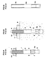
- FIGS 14 and 15, of the accompanying drawings show an anchor bolt of previously proposed kind comprising an anchor body member 1 formed as a rod 2 with an expansion body 3 at one of its ends and a male screw thread 4 at the other of its ends.
- a reduced diameter portion 5 is formed adjacent the expansion body 3, and an expansible sleeve 6 is mounted on the portion 5.
- the expansible sleeve 6 is ride by die-cutting a thin metal plate and rolling it into a cylindrical shape with an outer diameter almost the same as that of the male screw 4.
- the expansible sleeve 6 is loosely fitted on the reduced diameter portion 5 and has on its outer surface gripping protrusions 7 which prevent the sleeve from being pulled out of a bore 9 in a concrete body 8.
- the anchor bolt is pressed into the bore 9 in the concrete body 8, with its expansion body 3 positioned deepest in the bore 9.
- the gripping protrusions 7 of the expansible sleeve 6 engage with an inner surface of the bore 9.
- a nut 10 put on the male screw thread 4 is tightened to secure an object 11 which is to be mounted on the concrete body.
- a pulling force thereby imparted to the anchor body 1 causes a tapered surface 3 a of the expansion body 3 forcibly to expand the expansible sleeve 6, whereby the anchor body is fastened to the concrete body 8.
- the anchor bolt described above is simple in its structure since the diameter of the rod 2 of the anchor body 1, a maxim diameter of the expansion body 3, the outer diameters of the male screw thread 4 and of the expansible sleeve 6 are almost the same. Therefore, the bore 9 drilled in the concrete body 8 can have a minimum diameter, which provides a great advantage to the related construction works.
- the anchor body 1 has been manufactured from a raw rod 2A of a diameter equal to the diameter of the thread of the male screw thread 4, by a cutting or machining technique removing portions 2 b and 2 c shown in Figure 16 to form the enlarged head 3, the reduced diameter portion 5 and the screw thread 4.
- Such a manufacturing method is disadvantageous in that productivity is low, yield of good products is low and the cost of manufacture is high.
- a method of manufacturing an anchor bolt comprising the steps of: preliminarily heading a first end of a steel rod to form a preliminary head having a tapered surface which tapers, decreasing in diameter, from the first end towards a middle portion of the steel rod; thread rolling a second end of the steel rod to form a male screw thread on the steel rod having a core diameter substantially equal to the smallest diameter of the tapered surface; rolling an intermediate portion of the steel rod adjacent to the preliminary head simultaneously with the thread rolling to form a reduced diameter rod-portion by gradually inwardly displacing a surface layer of the intermediate portion causing an inner transient swell in the axial direction of the steel rod to form a stopper and radially outwardly displacing the surface layer causing an outer transient swell to form a tapered portion merging into the tapered surface of the preliminary head thereby to form a frustum-shaped expansion body; and die-cutting and bending a thin metal plate into a cylindrical shaped
- apparatus for manufacturing an anchor body of an anchor bolt comprising: a header means including a pair of header dies to press a first end portion of a steel rod to form a preliminary head having a tapered surface which tapers, decreasing in diameter, from a first end toward a middle portion of the steel rod; and a pair of rolling die assemblies each including a neck-rolling die overlying and fixedly secured to a thread-rolling die with a spacer interposed therebetween, the thread-rolling die forming a male screw thread on a second end of the steel rod opposite to the first end thereof, and the neck-rolling die forming a reduced diameter rod-portion; wherein the neck-rolling dies each include an upper slope, a lower slope, and a vertical forging surface formed with a sharp edge located foremost of the respective neck-rolling dies in the direction of movement of the rolling die assemblies, a rear width of the vertical forging surface of each of the neck-rolling dies gradually increases with widths of
- Such a method and apparatus can employ a simple but effective means suited to mass production of the described anchor bolts at a lower cost.
- the method includes forming a plurality of deep notches extending axially from a first end of the expansible sleeve toward a second end thereof, and a plurality of spring tongues respectively disposed between adjacent ones of the deep notches.
- the method preferably includes assembling the bolt by loosely fitting the expansible sleeve on the intermediate portion with the plurality of tongues being engageable with and retained by the stopper, and the first end of the expansible sleeve co-operating with the expansion body.
- the plurality of spring tongues are formed by partially slitting the other end and by bending parts disposed between the adjacent slits outwardly in a radial direction.
- the header and the pair of rolling die assemblies combined therewith are thus suited for the mass production of the anchor body.
- the expansihle sleeve also can be mass-produced by die-cutting and bending the thin metal plate.
- the method of the invention is composed of two steps, which are the step of preliminarily heading the steel rod of a diameter substantially equal to that of the core diameter of the rolled male screw thread, by an ordinary header, and the step of subsequently rolling the rod by a pair of rolling die assemblies.
- the apparatus of the invention can be of a simpler structure which can be built inexpensively and which nevertheless makes it easier to carry out the method in the invention.
- the expansible sleeve which is to be combined with the anchor body can be made by die-cutting and bending the thin metal plate to comprise the spring tongues which are formed by partially slitting one end portion and by subsequently bending the parts between the adjacent slits outwardly and radially.
- Such a structure of the expansible sleeve is advantageous not only in that it can be manufactured simply and low in cost, but also in that it can be inserted smoothly into a bore formed in a concrete structure and be expanded easily therein whereby construction works are rendered easier.
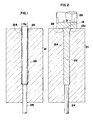
- Figures 1 and 2 illustrate a header which is used to perform a first step of preliminarily heading a steel rod 12A or anchor bolt blank.
- a header die 21 has a bore 22 into which the steel rod 12A is inserted.
- a head-forming recess 23 is located at an upper end of the bore 22, and an ejection pin 24 is fitted in a bore aligned with that bottom end of the bore 22.
- the steel rod 12A is of a diameter d0 substantially equal to a core diameter of a male screw thread 14 to be formed by a rolling technique as shown in Figure 10.
- Figure 2 illustrates a heading punch 25 which presses one end of the steel rod 12A protruding from the bore 22 of the header die 21.
- a preliminary head 13 is thus formed by the head-forming recess 23, with the preliminary head having a tapered surface 13 a which tapers, decreasing its diameter, from said one end towards a middle portion of the rod 12A.
- the maximum diameter of the preliminary head 13 is substantially equal to an outer diameter D of the male screw thread 14.
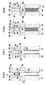
- a rolling die assembly 30 comprises a thread-rolling die 31 to form the male screw thread 14 at the other end the steel rod 12A which has undergone the preliminary forming step, a spacer 32 overlying the thread-rolling die 31, and a neck-rolling die 33 overlying the spacer 32 so as to be fixedly secured to the thread-rolling die 31.
- the neck-rolling die 33 is of a shape such that a rod-portion 15 of reduced diameter is formed as illustrated in Figure 10.
- the neck-rolling die 33 has an upper slope 35 and a lower slope 36 which constitute one of vertical forging surfaces 34 which are opposed in a pair of the rolling die assemblies 30.
- Each vertical forging surface 34 is formed as a sharp ridge located foremost in a direction denoted by an arrow in Figure 3, in which direction the assembly moves.
- a rear width of the forging surfaces 34 gradually increases, with widths of the upper slope 35 and the lower slope 36 gradually decreasing at the same time.
- a rear portion of the upper slope 35 gradually merges into a further slope 37 which is inclined at the same angle as the tapered surface 13 a of the preliminary head 13, while a rear portion of the lower slope 36 gradually merges into a stepped recess 38 which is to form a stopper 16 at an end of the rod-portion 15 of reduced diameter.
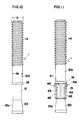
- the stopper 16 is produced to have a flange- like shape with a diameter substantially equal to the outer diameter of the male screw thread 14, as shown in Figure 9.
- the further slope 37 in the rear or right-hand region forcibly deforms the outer transient swell 17 into a tapered portion 19 which merges into and adjoins the tapered surface 13a of the preliminary head 13, so as to form an integral tapered region.
- the tapered surface 13a is thus elongated to the end of the reduced diameter rod-portion 15 and has a desirable length, whereby an expansion body 20 of a pre-determined frustum shape is provided for an anchor body 1 as illustrated in Figure 10.
- the expansible sleeve 41 is made of a thin rectangular metal plate 42, as illustrated in Figure 13. Deep notches 43 are formed to extend from one edge towards an opposite edge. Pair of slits 44 spaced apart an adequate distance are also formed at said opposite edge. Then, the metal plate 42 is rolled into a cylindrical shape with an outer diameter substantially equal to that of the male screw thread 14, as shown in Figure 12. Expansible tongues 45 are formed between two adjacent ones of the deep notches 43 or between one such notch and a side edge of the metal plate 42. The parts of the metal plate 42 which are disposed between the paired adjacent slits 44 are bent outwardly in a radial direction so as to form spring tongues 46. Said opposite edge, at which the spring tongues 46 are located, engages with and is retained by the stopper 16 when the expansible sleeve 41 is loosely fitted on the reduced diameter rod-portion 15.
- the expansible sleeve 41 is not rigid but rather has spring-characteristics. Consequently, it does not exert any strong resistance when inserted in a bore of a concrete structure so that the pushing of the sleeve by any tool or part thereof such as a, grip of a hammer will be enough to set the expansible sleeve 41 in position within the bore. Further, such an expansible sleeve 41 is ready to expand in the bore 9 and is so securely fixed therein that it cannot be withdrawn therefrom.
Landscapes
- Engineering & Computer Science (AREA)
- Mechanical Engineering (AREA)
- General Engineering & Computer Science (AREA)
- Forging (AREA)
- Dowels (AREA)
Applications Claiming Priority (2)
| Application Number | Priority Date | Filing Date | Title |
|---|---|---|---|
| JP295788/89 | 1989-11-14 | ||
| JP1295788A JPH03161136A (ja) | 1989-11-14 | 1989-11-14 | コンクリート用アンカーボルトの製造方法及び該アンカーボルトの製造に用いる装置 |
Publications (2)
| Publication Number | Publication Date |
|---|---|
| EP0428317A2 true EP0428317A2 (fr) | 1991-05-22 |
| EP0428317A3 EP0428317A3 (en) | 1992-09-02 |
Family
ID=17825169
Family Applications (1)
| Application Number | Title | Priority Date | Filing Date |
|---|---|---|---|
| EP19900312137 Withdrawn EP0428317A3 (en) | 1989-11-14 | 1990-11-06 | Method and apparatus for manufacturing an anchor bolt |
Country Status (8)
| Country | Link |
|---|---|
| US (1) | US4996860A (fr) |
| EP (1) | EP0428317A3 (fr) |
| JP (1) | JPH03161136A (fr) |
| AU (1) | AU6659890A (fr) |
| DE (1) | DE4009690A1 (fr) |
| FI (1) | FI905476A7 (fr) |
| HU (1) | HUT58572A (fr) |
| NO (1) | NO904922L (fr) |
Cited By (7)
| Publication number | Priority date | Publication date | Assignee | Title |
|---|---|---|---|---|
| EP0776712A1 (fr) * | 1995-11-29 | 1997-06-04 | PI-GI S.r.l. | Méthode de fabrication de vis spéciale pour charnières de meuble et vis obtenues par cette méthode |
| EP0796680A1 (fr) * | 1996-03-19 | 1997-09-24 | Eric Bedouet | Perfectionnement pour procédé de réalisation de goujons ou tirants filetés |
| EP1186360A3 (fr) * | 2000-08-10 | 2002-12-18 | Adolf Würth GmbH & Co. KG | Procédé et dispositif pour la fabrication d'éléments de visserie |
| WO2015044627A1 (fr) * | 2013-09-24 | 2015-04-02 | Excalibur Screwbolts Limited | Perfectionnements apportés ou se rapportant à des boulons d'ancrage |
| CN109967982A (zh) * | 2019-04-28 | 2019-07-05 | 中船重工海为郑州高科技有限公司 | 一种风力发电机组用圆弧螺纹锚栓组件的制备方法 |
| CN112008347A (zh) * | 2020-10-09 | 2020-12-01 | 李少燕 | 一种建筑锚固螺栓加工方法 |
| CN113635493A (zh) * | 2021-08-18 | 2021-11-12 | 河北万达轮胎有限公司 | 一种风胎硫化机的锁模结构 |
Families Citing this family (18)
| Publication number | Priority date | Publication date | Assignee | Title |
|---|---|---|---|---|
| US5381682A (en) * | 1993-12-17 | 1995-01-17 | Great Lakes Tool And Machine Co. | Apparatus and method of manufacturing masonry fasteners |
| US5776001A (en) * | 1994-02-16 | 1998-07-07 | Ccl Systems Limited | Thread formation |
| JP4836360B2 (ja) * | 2001-07-11 | 2011-12-14 | 株式会社青山製作所 | 転造ダイス |
| US7140826B2 (en) | 2002-10-30 | 2006-11-28 | Powers Fasteners, Inc. | Shaped anchor |
| US8974163B2 (en) * | 2008-09-09 | 2015-03-10 | Mechanical Plastics Corp. | Wedge-type drop-in anchor assembly |
| US20100143067A1 (en) * | 2008-11-03 | 2010-06-10 | Powers Fasteners, Inc. | Anchor bolt and method for making same |
| EP2533919B1 (fr) | 2010-02-12 | 2017-06-07 | HILTI Aktiengesellschaft | Procédé de formation de boulons d'ancrage |
| DE102011076180A1 (de) * | 2011-05-20 | 2012-11-22 | Hilti Aktiengesellschaft | Ankerbolzen und Herstellungsverfahren |
| CN102728750B (zh) * | 2012-06-11 | 2014-07-30 | 河南航天精工制造有限公司 | 铆钉芯杆断径槽加工装置 |
| KR101425633B1 (ko) | 2012-09-07 | 2014-08-13 | 김용운 | 앵커 볼트 헤드부 성형 장치 |
| EP2886881A1 (fr) * | 2013-12-19 | 2015-06-24 | HILTI Aktiengesellschaft | Cheville à expansion avec sécurité anti-rotation |
| CN106216574A (zh) * | 2016-08-31 | 2016-12-14 | 天津众信机械制造有限公司 | 一种适用多规格螺丝成型模具 |
| CN106640903B (zh) | 2016-12-23 | 2019-06-21 | 北京金风科创风电设备有限公司 | 定心紧固件、其制作方法、使用方法及风力发电机组 |
| CN110026742A (zh) * | 2019-04-29 | 2019-07-19 | 成都现代万通锚固技术有限公司 | 一种锚钎杆的制造工艺 |
| CN111571145B (zh) * | 2020-05-28 | 2021-06-22 | 珠海经济特区华凯工贸有限公司 | 一种自攻螺钉生产加工方法 |
| CN112139773A (zh) * | 2020-10-15 | 2020-12-29 | 太仓市兴建机械铸造厂 | 一种新型多片式快起膨胀螺栓加工工艺 |
| US12000421B2 (en) | 2021-01-07 | 2024-06-04 | Illinois Tool Works Inc. | Self-drilling self-tapping fastener |
| CN114718191B (zh) * | 2022-03-16 | 2024-09-27 | 苏州思萃融合基建技术研究所有限公司 | 一种半包gfrp抗剪连接件及结构墙板和墙板的加工方法 |
Family Cites Families (12)
| Publication number | Priority date | Publication date | Assignee | Title |
|---|---|---|---|---|
| US3044332A (en) * | 1959-02-17 | 1962-07-17 | Olympic Screw & Rivet Corp | Method of making rivet pins |
| CA953958A (en) * | 1973-02-19 | 1974-09-03 | Joan P. Seetaram | Anchor bolt |
| JPS52144564A (en) * | 1976-05-28 | 1977-12-01 | Sannohashi Seisakushiyo Kk | Method of manufacturing torque limitation bolt |
| GB1594943A (en) * | 1977-01-13 | 1981-08-05 | Avdel Ltd | Method of making a mandrel for a self-plugging blind rivet |
| JPS53114756A (en) * | 1977-03-18 | 1978-10-06 | Sannohashi Seisakushiyo Kk | Production of hub bolt |
| DE2839495A1 (de) * | 1977-09-20 | 1979-03-29 | Torben Bredal | Verankerungsbuchse |
| CH624738A5 (en) * | 1977-09-29 | 1981-08-14 | Egli Fischer & Co | Anchoring bolt |
| FR2414375A1 (fr) * | 1979-01-12 | 1979-08-10 | Warnke Umformtech Veb K | Procede de laminage transversal de pieces decolletees a symetrie de rotation de forme allongee |
| JPS6011578B2 (ja) * | 1982-02-22 | 1985-03-27 | 株式会社阪村機械製作所 | ホ−マ−における連続圧造転造方法及び装置 |
| GB8405402D0 (en) * | 1984-03-01 | 1984-04-04 | Dom Holdings Plc | Expansion anchor |
| JPS6247616A (ja) * | 1985-08-27 | 1987-03-02 | Konishiroku Photo Ind Co Ltd | レ−ザ走査装置 |
| JPH01104434A (ja) * | 1987-10-19 | 1989-04-21 | Toyota Motor Corp | コネクティングロッドボルトの製造方法 |
-
1989
- 1989-11-14 JP JP1295788A patent/JPH03161136A/ja active Granted
-
1990
- 1990-03-21 US US07/496,663 patent/US4996860A/en not_active Expired - Fee Related
- 1990-03-26 DE DE4009690A patent/DE4009690A1/de active Granted
- 1990-11-05 FI FI905476A patent/FI905476A7/fi not_active IP Right Cessation
- 1990-11-06 EP EP19900312137 patent/EP0428317A3/en not_active Withdrawn
- 1990-11-12 HU HU907103A patent/HUT58572A/hu unknown
- 1990-11-13 AU AU66598/90A patent/AU6659890A/en not_active Abandoned
- 1990-11-13 NO NO90904922A patent/NO904922L/no unknown
Cited By (7)
| Publication number | Priority date | Publication date | Assignee | Title |
|---|---|---|---|---|
| EP0776712A1 (fr) * | 1995-11-29 | 1997-06-04 | PI-GI S.r.l. | Méthode de fabrication de vis spéciale pour charnières de meuble et vis obtenues par cette méthode |
| EP0796680A1 (fr) * | 1996-03-19 | 1997-09-24 | Eric Bedouet | Perfectionnement pour procédé de réalisation de goujons ou tirants filetés |
| EP1186360A3 (fr) * | 2000-08-10 | 2002-12-18 | Adolf Würth GmbH & Co. KG | Procédé et dispositif pour la fabrication d'éléments de visserie |
| WO2015044627A1 (fr) * | 2013-09-24 | 2015-04-02 | Excalibur Screwbolts Limited | Perfectionnements apportés ou se rapportant à des boulons d'ancrage |
| CN109967982A (zh) * | 2019-04-28 | 2019-07-05 | 中船重工海为郑州高科技有限公司 | 一种风力发电机组用圆弧螺纹锚栓组件的制备方法 |
| CN112008347A (zh) * | 2020-10-09 | 2020-12-01 | 李少燕 | 一种建筑锚固螺栓加工方法 |
| CN113635493A (zh) * | 2021-08-18 | 2021-11-12 | 河北万达轮胎有限公司 | 一种风胎硫化机的锁模结构 |
Also Published As
| Publication number | Publication date |
|---|---|
| DE4009690C2 (fr) | 1991-10-10 |
| NO904922L (no) | 1991-05-15 |
| EP0428317A3 (en) | 1992-09-02 |
| JPH03161136A (ja) | 1991-07-11 |
| HU907103D0 (en) | 1991-05-28 |
| US4996860A (en) | 1991-03-05 |
| AU6659890A (en) | 1991-05-23 |
| JPH0462819B2 (fr) | 1992-10-07 |
| FI905476A0 (fi) | 1990-11-05 |
| DE4009690A1 (de) | 1991-05-16 |
| HUT58572A (en) | 1992-03-30 |
| NO904922D0 (no) | 1990-11-13 |
| FI905476A7 (fi) | 1991-05-15 |
Similar Documents
| Publication | Publication Date | Title |
|---|---|---|
| EP0428317A2 (fr) | Procédé et dispositif pour la fabrication d'un boulon d'ancrage | |
| US4233878A (en) | Barb and method of making same | |
| US4451189A (en) | Bulb rivet | |
| US4659267A (en) | Prefastenable torque-shear bolt | |
| EP1086316B1 (fr) | Procede servant a fabriquer un element tubulaire | |
| US4765010A (en) | Method of making a stem for a self-plugging blind fastener | |
| US4389766A (en) | Method of mounting a fastener | |
| US3451080A (en) | Screws | |
| US5027996A (en) | Method of manufacturing a hollow shaft with internal swellings of revolution and shaft obtained by this method | |
| EP1572393B1 (fr) | Matrice segmentee pour formation de pieces a usiner rainurees | |
| EP0351702A2 (fr) | Dispositif de fixation aveugle | |
| CA2168197A1 (fr) | Methode d'assemblage des elements d'un ensemble | |
| CA2126114A1 (fr) | Mandrin pour rivets pleins et appareil pour la fabrication dudit mandrin | |
| US5357776A (en) | Method of forming bushing rings | |
| US2814059A (en) | Method for making serrated-head bolts | |
| EP0638378B1 (fr) | Méthode pour la fabrication de la tige d'un rivet borgne | |
| US6558263B1 (en) | Forging method of a hollow part | |
| NO311455B1 (no) | Slaganker | |
| AU661196B2 (en) | Method of making a tubular body having a deformable internal skirt | |
| JPH0741348B2 (ja) | 前方押出し加工方法およびその装置 | |
| JPH05104190A (ja) | 金属製の拡張栓の製造法 | |
| JPH109234A (ja) | アンカーの製造方法及びアンカー |
Legal Events
| Date | Code | Title | Description |
|---|---|---|---|
| PUAI | Public reference made under article 153(3) epc to a published international application that has entered the european phase |
Free format text: ORIGINAL CODE: 0009012 |
|
| AK | Designated contracting states |
Kind code of ref document: A2 Designated state(s): AT BE CH DK ES FR GB IT LI NL SE |
|
| PUAL | Search report despatched |
Free format text: ORIGINAL CODE: 0009013 |
|
| AK | Designated contracting states |
Kind code of ref document: A3 Designated state(s): AT BE CH DK ES FR GB IT LI NL SE |
|
| RAP1 | Party data changed (applicant data changed or rights of an application transferred) |
Owner name: YUGEN KAISHA SHINJOSEISAKUSHO |
|
| STAA | Information on the status of an ep patent application or granted ep patent |
Free format text: STATUS: THE APPLICATION IS DEEMED TO BE WITHDRAWN |
|
| 18D | Application deemed to be withdrawn |
Effective date: 19930303 |