EP0796684A2 - Petite face de confinement electromagnétique pour machine de coulée continue de bandes - Google Patents
Petite face de confinement electromagnétique pour machine de coulée continue de bandes Download PDFInfo
- Publication number
- EP0796684A2 EP0796684A2 EP97104701A EP97104701A EP0796684A2 EP 0796684 A2 EP0796684 A2 EP 0796684A2 EP 97104701 A EP97104701 A EP 97104701A EP 97104701 A EP97104701 A EP 97104701A EP 0796684 A2 EP0796684 A2 EP 0796684A2
- Authority
- EP
- European Patent Office
- Prior art keywords
- magnetic flux
- coil
- flux conductor
- arms
- yoke
- Prior art date
- Legal status (The legal status is an assumption and is not a legal conclusion. Google has not performed a legal analysis and makes no representation as to the accuracy of the status listed.)
- Ceased
Links
Images




Classifications
-
- B—PERFORMING OPERATIONS; TRANSPORTING
- B22—CASTING; POWDER METALLURGY
- B22D—CASTING OF METALS; CASTING OF OTHER SUBSTANCES BY THE SAME PROCESSES OR DEVICES
- B22D11/00—Continuous casting of metals, i.e. casting in indefinite lengths
- B22D11/06—Continuous casting of metals, i.e. casting in indefinite lengths into moulds with travelling walls, e.g. with rolls, plates, belts, caterpillars
- B22D11/0622—Continuous casting of metals, i.e. casting in indefinite lengths into moulds with travelling walls, e.g. with rolls, plates, belts, caterpillars formed by two casting wheels
-
- B—PERFORMING OPERATIONS; TRANSPORTING
- B22—CASTING; POWDER METALLURGY
- B22D—CASTING OF METALS; CASTING OF OTHER SUBSTANCES BY THE SAME PROCESSES OR DEVICES
- B22D11/00—Continuous casting of metals, i.e. casting in indefinite lengths
- B22D11/06—Continuous casting of metals, i.e. casting in indefinite lengths into moulds with travelling walls, e.g. with rolls, plates, belts, caterpillars
- B22D11/0637—Accessories therefor
- B22D11/0648—Casting surfaces
- B22D11/066—Side dams
- B22D11/0662—Side dams having electromagnetic confining means
-
- B—PERFORMING OPERATIONS; TRANSPORTING
- B22—CASTING; POWDER METALLURGY
- B22D—CASTING OF METALS; CASTING OF OTHER SUBSTANCES BY THE SAME PROCESSES OR DEVICES
- B22D11/00—Continuous casting of metals, i.e. casting in indefinite lengths
- B22D11/10—Supplying or treating molten metal
- B22D11/11—Treating the molten metal
Definitions
- molten metal can solidify against the refractory cover on the liquid-cooled mechanical dam, and the solidified metal can grow from the mechanical dam and bridge the clearance between the dam and a rotating casting roll.
- rotation of the casting roll can cause solidified bridging metal to rip off the refractory cover on the liquid-cooled mechanical dam, which is undesireable, and there can be other operational problems including electrical shorts.
- the coils associated with the magnetic flux conductors can all be totally remote from the pool of molten metal.
- a coil associated with the magnetic flux conductors comprises at least one coil portion having a front surface which (a) faces the open end of the space between the casting rolls and (b) is sufficiently proximate to the open end to enable the direct generation of a horizontal magnetic field which extends through that open end to the pool of molten metal.
- the second magnetic flux conductor may be integral with and comprise a downward extension of the first magnetic flux conductor.
- the third magnetic flux conductor terminates downwardly at a location substantially above the downward termination of the second magnetic flux conductor.
- Space 35 between rolls 31, 32 has an open end 36 (Fig. 3), and located adjacent open end 36 is an electromagnetic dam 40 for preventing the escape of molten metal through open end 36 of space 35.
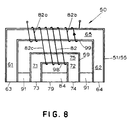
- Magnetic confining apparatus 50 comprises a first magnetic flux conductor 51 having a relatively wide upper part 52 facing the top part 41 of molten metal pool 38 (Fig. 2), when the latter is at its maximum height. Wide upper part 52 of first magnetic flux conductor 51 defines a relatively wide air gap 53.
- a second magnetic flux conductor 55 is located below first magnetic flux conductor 51 and constitutes a downward extension of the latter. Second magnetic flux conductor 55 has a relatively narrow part 56 facing the bottom part 42 of molten metal pool 38 at nip 37 and defines a relatively narrow air gap 57.
- a third magnetic flux conductor 59 Located in relatively wide air gap 53, defined by wide upper part 52 of the first magnetic flux conductor, is a third magnetic flux conductor 59.
- Coil 81 is wrapped around yoke 75 of third magnetic flux conductor 59 (Fig. 5). Coil 81 provides a time-varying electric current in electromagnetic association with third magnetic flux conductor 59, and this develops, at relatively wide air gap 53, additional magnetic flux which augments at least part of the magnetic flux developed by first magnetic flux conductor 51 and its associated coil 80.
- Flux 77 flows externally from surface 63 on first magnetic flux conductor 51 to surface 64 thereon and then internally through the first magnetic flux conductor back to surface 63 thereon. Flux 77 also flows externally from surface 63 to surface 73 on third magnetic flux conductor 59, then internally through the third magnetic flux conductor to surface 74 thereon, then externally to surface 64 on first magnetic flux conductor 51 and then internally through the first magnetic flux conductor back to surface 63 thereon.
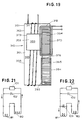
- FIG. 21 Diagrams of examples of circuits for producing the in-phase and phase-shifted conditions are depicted in Figs. 21 and 22, respectively.
- Current flow is in the direction of the arrows in Figs. 21 and 22.
- coils 80 and 81 are connected in series across an audio frequency power supply 101, and a capacitor assembly 102 is connected in parallel with the series of coils 80, 81.
- the current in coil 80 is in phase with the current in coil 81.
- Fig. 22 there is a resistor 103 in parallel with coil 81, and the current in coil 80 is phase-shifted with respect to the current in coil 81.
- the phase shift can be adjusted by changing the resistance at 103.
- the magnetic field topography relevant here is the intensity distribution of the magnetic field strength (B), between the dam (e.g., 50) and molten metal pool 38, in a direction along the width of pool 38.
- Each arm of bifurcated upper part 91 of conductor element 85 has a rectangular, horizontal cross-section.
- Lower part 92 of conductor element 85 has a rectangular, horizontal cross-section and a downwardly, arcuately tapering front surface 90 facing lower part 42 of molten metal pool 38.
- Conductor elements 84 and 85 are hollow and may be liquid cooled in a conventional manner.
- coil 82 has a pair of outer coil parts 82a, 82b, associated only with first and second magnetic flux conductors 51, 55, and a middle coil part 82c associated with third magnetic flux conductor 59.
- the embodiments of Figs. 6 and 8 are essentially identical in structure; and the operation of both embodiments is essentially the same.
- All of the surfaces on the three magnetic flux conductors in dam 150 are substantially enclosed by non-magnetic electrically conductive material except for spaced-apart surfaces 63, 64 on first and second magnetic flux conductors 151, 155 and spaced-apart, pool-facing, surfaces 73, 74 on third magnetic flux conductor 159.
- Dam 110 comprises first, second and third magnetic flux conductors 111, 112 and 113 respectively, each conforming structurally to the first, second and third magnetic flux conductors in the embodiments of Figs. 4-6 and 8.
- Third magnetic flux conductor 113 comprises a pair of spaced-apart arms 121, 122 extending from a yoke 125 and each terminating at a respective one of a pair of spaced-apart, pool-facing end surfaces 123, 124.
- Spaced-apart surfaces 117, 118 on first magnetic flux conductor 111 are opposite casting roll rim portions 44, 43 respectively (Fig. 2) and are adjacent top part 41 of molten metal pool 38 (Fig. 2); also adjacent the pool's top part are spaced-apart surfaces 123, 124 of third magnetic flux conductor 113.
- the spaced-apart end surfaces on second magnetic flux conductor 112 are disposed opposite rim portions 43, 44 and are adjacent bottom part 42 of molten metal pool 38 (Fig. 2).
- first coil portion 126 Electrically connected to first coil portion 126 is a hollow, second coil portion 120 having a yoke 130 from which extend a pair of spaced-apart arms 128, 129.
- Yoke 130 is located between yoke 125 of third magnetic flux conductor 113 and yoke 119 of first and second magnetic flux conductors 111, 112.
- Arm 128 on second coil portion 120 is located between arm 121 on third magnetic flux conductor 113 and arm 115 on first and second magnetic flux conductors 111, 112.
- Arm 129 on second coil portion 120 is located between arm 122 on third magnetic flux conductor 113 and arm 116 on first and second magnetic flux conductors 111, 112.
- the non-magnetic, electrically conductive elements namely coil portions 126, 120 and 132, act to confine that part of the magnetic field which is outside of its low reluctance return path to substantially open end 36 of space 35 between the two casting rolls (Fig. 3).
- a second coil portion 232 is located exteriorly of first and second magnetic flux conductors 211, 212 and is substantially vertically co-extensive with them.
- Second coil portion 232 comprises a pair of arms 237, 238 extending from a yoke 239.
- Second coil portion 232 is electrically connected with each of coil parts 226, 228 and 229 of first coil portion 230, at the bottom extremity of each such coil part, by a shorting element 231 (Figs. 9 and 11).
Landscapes
- Engineering & Computer Science (AREA)
- Mechanical Engineering (AREA)
- Physics & Mathematics (AREA)
- Electromagnetism (AREA)
- Continuous Casting (AREA)
- Shielding Devices Or Components To Electric Or Magnetic Fields (AREA)
Applications Claiming Priority (2)
| Application Number | Priority Date | Filing Date | Title |
|---|---|---|---|
| US619914 | 1996-03-20 | ||
| US08/619,914 US5695001A (en) | 1996-03-20 | 1996-03-20 | Electromagnetic confining dam for continuous strip caster |
Publications (2)
| Publication Number | Publication Date |
|---|---|
| EP0796684A2 true EP0796684A2 (fr) | 1997-09-24 |
| EP0796684A3 EP0796684A3 (fr) | 1998-09-09 |
Family
ID=24483839
Family Applications (1)
| Application Number | Title | Priority Date | Filing Date |
|---|---|---|---|
| EP97104701A Ceased EP0796684A3 (fr) | 1996-03-20 | 1997-03-19 | Petite face de confinement electromagnétique pour machine de coulée continue de bandes |
Country Status (8)
| Country | Link |
|---|---|
| US (1) | US5695001A (fr) |
| EP (1) | EP0796684A3 (fr) |
| JP (1) | JP2795841B2 (fr) |
| KR (1) | KR100266158B1 (fr) |
| CA (1) | CA2200153A1 (fr) |
| RU (1) | RU2132251C1 (fr) |
| TW (1) | TW358046B (fr) |
| ZA (1) | ZA972376B (fr) |
Families Citing this family (3)
| Publication number | Priority date | Publication date | Assignee | Title |
|---|---|---|---|---|
| US6123798A (en) * | 1998-05-06 | 2000-09-26 | Caliper Technologies Corp. | Methods of fabricating polymeric structures incorporating microscale fluidic elements |
| IL144972A0 (en) * | 2001-08-19 | 2002-06-30 | Nat Diversified Ind Aust Pty L | Continuous casting of metal sheets and bands |
| CN112355258B (zh) * | 2020-10-28 | 2022-06-17 | 晟通科技集团有限公司 | 挡板及铝材熔融装置 |
Family Cites Families (7)
| Publication number | Priority date | Publication date | Assignee | Title |
|---|---|---|---|---|
| US4974661A (en) * | 1988-06-17 | 1990-12-04 | Arch Development Corp. | Sidewall containment of liquid metal with vertical alternating magnetic fields |
| US4936374A (en) * | 1988-11-17 | 1990-06-26 | The United States Of America As Represented By The United States Department Of Energy | Sidewall containment of liquid metal with horizontal alternating magnetic fields |
| EP0586732B1 (fr) * | 1992-06-22 | 1998-03-25 | Inland Steel Company | Dispositif et procédé de confinement d'un métal liquide par magnétisme |
| US5197534A (en) * | 1991-08-01 | 1993-03-30 | Inland Steel Company | Apparatus and method for magnetically confining molten metal |
| US5251685A (en) * | 1992-08-05 | 1993-10-12 | Inland Steel Company | Apparatus and method for sidewall containment of molten metal with horizontal alternating magnetic fields |
| US5495886A (en) * | 1994-04-29 | 1996-03-05 | Inland Steel Company | Apparatus and method for sidewall containment of molten metal with vertical magnetic fields |
| US5487421A (en) * | 1994-06-22 | 1996-01-30 | Inland Steel Company | Strip casting apparatus with electromagnetic confining dam |
-
1996
- 1996-03-20 US US08/619,914 patent/US5695001A/en not_active Expired - Fee Related
-
1997
- 1997-03-17 CA CA002200153A patent/CA2200153A1/fr not_active Abandoned
- 1997-03-19 EP EP97104701A patent/EP0796684A3/fr not_active Ceased
- 1997-03-19 ZA ZA9702376A patent/ZA972376B/xx unknown
- 1997-03-19 RU RU97104363A patent/RU2132251C1/ru active
- 1997-03-20 KR KR1019970009577A patent/KR100266158B1/ko not_active Expired - Fee Related
- 1997-03-21 JP JP9067724A patent/JP2795841B2/ja not_active Expired - Lifetime
- 1997-04-22 TW TW086103513A patent/TW358046B/zh active
Also Published As
| Publication number | Publication date |
|---|---|
| US5695001A (en) | 1997-12-09 |
| KR100266158B1 (ko) | 2000-09-15 |
| JP2795841B2 (ja) | 1998-09-10 |
| KR970064780A (ko) | 1997-10-13 |
| CA2200153A1 (fr) | 1997-09-20 |
| EP0796684A3 (fr) | 1998-09-09 |
| ZA972376B (en) | 1997-09-29 |
| AU1629997A (en) | 1997-09-25 |
| MX9603649A (es) | 1997-09-30 |
| RU2132251C1 (ru) | 1999-06-27 |
| JPH105936A (ja) | 1998-01-13 |
| AU689400B2 (en) | 1998-03-26 |
| TW358046B (en) | 1999-05-11 |
Similar Documents
| Publication | Publication Date | Title |
|---|---|---|
| EP0867243B1 (fr) | Plaque électromagnétique d'obturation latérale pour dispositif de coulée de bandentre deux cylindres | |
| EP0531286B2 (fr) | Confinement lateral de metal liquide a l'aide de champs magnetiques alternatifs horizontaux | |
| EP0586072B1 (fr) | Dispositif et procédé pour confinement latéral de métal liquide à l'aide de champs magnétiques alternatifs horizontaux | |
| US5197534A (en) | Apparatus and method for magnetically confining molten metal | |
| US5695001A (en) | Electromagnetic confining dam for continuous strip caster | |
| EP0586732B1 (fr) | Dispositif et procédé de confinement d'un métal liquide par magnétisme | |
| EP0679461A2 (fr) | Dispositif et procédé pour confinement latéral de métal liquide à l'aide de champs magnétiques verticaux | |
| MXPA96003649A (en) | Confinante electromagnetic press for fundidorade tira conti | |
| US4842043A (en) | Mold stirrer | |
| CA2138486C (fr) | Confinement electromagnetique de metal en fusion avec l'aide d'un courant de conduction | |
| AU708158B2 (en) | Strip casting apparatus with electromagnetic confining dam | |
| EP0737531B1 (fr) | Confinement électromagnétique des métaux liquides par conduction de courant | |
| CA2071169C (fr) | Methode et appareil pour le confinement magnetique d'un metal en fusion | |
| JP2813151B2 (ja) | 伝導電流の補助により溶融金属を電磁気的に閉じ込める装置及び方法 | |
| WO1994011134A1 (fr) | Appareil et procede de confinement magnetique du metal fondu | |
| HK1011626B (en) | Electromagnetic confinement of molten metal with conduction current assistance | |
| RU2109594C1 (ru) | Устройство и способ для магнитного удержания расплавленного металла | |
| AU669832B1 (en) | Electromagnetic confinement of molten metal with conduction current assistance | |
| KR100220372B1 (ko) | 자성을 이용한 용융금속의 누출 규제장치 및 방법 | |
| HK1011628B (en) | Strip casting apparatus with electromagnetic confining dam | |
| JPH08197212A (ja) | 溶融金属の連続鋳造方法および連続鋳造用鋳型 |
Legal Events
| Date | Code | Title | Description |
|---|---|---|---|
| PUAI | Public reference made under article 153(3) epc to a published international application that has entered the european phase |
Free format text: ORIGINAL CODE: 0009012 |
|
| AK | Designated contracting states |
Kind code of ref document: A2 Designated state(s): BE DE ES FR GB IT LU NL SE |
|
| PUAL | Search report despatched |
Free format text: ORIGINAL CODE: 0009013 |
|
| AK | Designated contracting states |
Kind code of ref document: A3 Designated state(s): BE DE ES FR GB IT LU NL SE |
|
| 17P | Request for examination filed |
Effective date: 19980924 |
|
| 17Q | First examination report despatched |
Effective date: 19990722 |
|
| GRAG | Despatch of communication of intention to grant |
Free format text: ORIGINAL CODE: EPIDOS AGRA |
|
| STAA | Information on the status of an ep patent application or granted ep patent |
Free format text: STATUS: THE APPLICATION HAS BEEN REFUSED |
|
| 18R | Application refused |
Effective date: 20010903 |