EP0796697A2 - Machine pour serrer un collier de serrage - Google Patents
Machine pour serrer un collier de serrage Download PDFInfo
- Publication number
- EP0796697A2 EP0796697A2 EP97301562A EP97301562A EP0796697A2 EP 0796697 A2 EP0796697 A2 EP 0796697A2 EP 97301562 A EP97301562 A EP 97301562A EP 97301562 A EP97301562 A EP 97301562A EP 0796697 A2 EP0796697 A2 EP 0796697A2
- Authority
- EP
- European Patent Office
- Prior art keywords
- band
- clamping
- lever
- fixing pieces
- metallic
- Prior art date
- Legal status (The legal status is an assumption and is not a legal conclusion. Google has not performed a legal analysis and makes no representation as to the accuracy of the status listed.)
- Granted
Links
Images



Classifications
-
- B—PERFORMING OPERATIONS; TRANSPORTING
- B25—HAND TOOLS; PORTABLE POWER-DRIVEN TOOLS; MANIPULATORS
- B25B—TOOLS OR BENCH DEVICES NOT OTHERWISE PROVIDED FOR, FOR FASTENING, CONNECTING, DISENGAGING, OR HOLDING
- B25B31/00—Hand tools for applying fasteners
-
- B—PERFORMING OPERATIONS; TRANSPORTING
- B23—MACHINE TOOLS; METAL-WORKING NOT OTHERWISE PROVIDED FOR
- B23P—METAL-WORKING NOT OTHERWISE PROVIDED FOR; COMBINED OPERATIONS; UNIVERSAL MACHINE TOOLS
- B23P19/00—Machines for simply fitting together or separating metal parts or objects, or metal and non-metal parts, whether or not involving some deformation; Tools or devices therefor so far as not provided for in other classes
- B23P19/04—Machines for simply fitting together or separating metal parts or objects, or metal and non-metal parts, whether or not involving some deformation; Tools or devices therefor so far as not provided for in other classes for assembling or disassembling parts
- B23P19/08—Machines for placing washers, circlips, or the like on bolts or other members
- B23P19/084—Machines for placing washers, circlips, or the like on bolts or other members for placing resilient or flexible rings, e.g. O-rings, circlips
- B23P19/086—Non-metallic protective bellows
-
- B—PERFORMING OPERATIONS; TRANSPORTING
- B23—MACHINE TOOLS; METAL-WORKING NOT OTHERWISE PROVIDED FOR
- B23P—METAL-WORKING NOT OTHERWISE PROVIDED FOR; COMBINED OPERATIONS; UNIVERSAL MACHINE TOOLS
- B23P19/00—Machines for simply fitting together or separating metal parts or objects, or metal and non-metal parts, whether or not involving some deformation; Tools or devices therefor so far as not provided for in other classes
- B23P19/04—Machines for simply fitting together or separating metal parts or objects, or metal and non-metal parts, whether or not involving some deformation; Tools or devices therefor so far as not provided for in other classes for assembling or disassembling parts
- B23P19/08—Machines for placing washers, circlips, or the like on bolts or other members
-
- F—MECHANICAL ENGINEERING; LIGHTING; HEATING; WEAPONS; BLASTING
- F16—ENGINEERING ELEMENTS AND UNITS; GENERAL MEASURES FOR PRODUCING AND MAINTAINING EFFECTIVE FUNCTIONING OF MACHINES OR INSTALLATIONS; THERMAL INSULATION IN GENERAL
- F16D—COUPLINGS FOR TRANSMITTING ROTATION; CLUTCHES; BRAKES
- F16D3/00—Yielding couplings, i.e. with means permitting movement between the connected parts during the drive
- F16D3/84—Shrouds, e.g. casings, covers; Sealing means specially adapted therefor
-
- Y—GENERAL TAGGING OF NEW TECHNOLOGICAL DEVELOPMENTS; GENERAL TAGGING OF CROSS-SECTIONAL TECHNOLOGIES SPANNING OVER SEVERAL SECTIONS OF THE IPC; TECHNICAL SUBJECTS COVERED BY FORMER USPC CROSS-REFERENCE ART COLLECTIONS [XRACs] AND DIGESTS
- Y10—TECHNICAL SUBJECTS COVERED BY FORMER USPC
- Y10T—TECHNICAL SUBJECTS COVERED BY FORMER US CLASSIFICATION
- Y10T29/00—Metal working
- Y10T29/49—Method of mechanical manufacture
- Y10T29/49826—Assembling or joining
- Y10T29/49908—Joining by deforming
-
- Y—GENERAL TAGGING OF NEW TECHNOLOGICAL DEVELOPMENTS; GENERAL TAGGING OF CROSS-SECTIONAL TECHNOLOGIES SPANNING OVER SEVERAL SECTIONS OF THE IPC; TECHNICAL SUBJECTS COVERED BY FORMER USPC CROSS-REFERENCE ART COLLECTIONS [XRACs] AND DIGESTS
- Y10—TECHNICAL SUBJECTS COVERED BY FORMER USPC
- Y10T—TECHNICAL SUBJECTS COVERED BY FORMER US CLASSIFICATION
- Y10T29/00—Metal working
- Y10T29/49—Method of mechanical manufacture
- Y10T29/49826—Assembling or joining
- Y10T29/49908—Joining by deforming
- Y10T29/49925—Inward deformation of aperture or hollow body wall
-
- Y—GENERAL TAGGING OF NEW TECHNOLOGICAL DEVELOPMENTS; GENERAL TAGGING OF CROSS-SECTIONAL TECHNOLOGIES SPANNING OVER SEVERAL SECTIONS OF THE IPC; TECHNICAL SUBJECTS COVERED BY FORMER USPC CROSS-REFERENCE ART COLLECTIONS [XRACs] AND DIGESTS
- Y10—TECHNICAL SUBJECTS COVERED BY FORMER USPC
- Y10T—TECHNICAL SUBJECTS COVERED BY FORMER US CLASSIFICATION
- Y10T29/00—Metal working
- Y10T29/49—Method of mechanical manufacture
- Y10T29/49826—Assembling or joining
- Y10T29/49908—Joining by deforming
- Y10T29/49938—Radially expanding part in cavity, aperture, or hollow body
- Y10T29/49941—Peripheral edge joining of abutting plates
-
- Y—GENERAL TAGGING OF NEW TECHNOLOGICAL DEVELOPMENTS; GENERAL TAGGING OF CROSS-SECTIONAL TECHNOLOGIES SPANNING OVER SEVERAL SECTIONS OF THE IPC; TECHNICAL SUBJECTS COVERED BY FORMER USPC CROSS-REFERENCE ART COLLECTIONS [XRACs] AND DIGESTS
- Y10—TECHNICAL SUBJECTS COVERED BY FORMER USPC
- Y10T—TECHNICAL SUBJECTS COVERED BY FORMER US CLASSIFICATION
- Y10T29/00—Metal working
- Y10T29/53—Means to assemble or disassemble
- Y10T29/5367—Coupling to conduit
-
- Y—GENERAL TAGGING OF NEW TECHNOLOGICAL DEVELOPMENTS; GENERAL TAGGING OF CROSS-SECTIONAL TECHNOLOGIES SPANNING OVER SEVERAL SECTIONS OF THE IPC; TECHNICAL SUBJECTS COVERED BY FORMER USPC CROSS-REFERENCE ART COLLECTIONS [XRACs] AND DIGESTS
- Y10—TECHNICAL SUBJECTS COVERED BY FORMER USPC
- Y10T—TECHNICAL SUBJECTS COVERED BY FORMER US CLASSIFICATION
- Y10T29/00—Metal working
- Y10T29/53—Means to assemble or disassemble
- Y10T29/53709—Overedge assembling means
-
- Y—GENERAL TAGGING OF NEW TECHNOLOGICAL DEVELOPMENTS; GENERAL TAGGING OF CROSS-SECTIONAL TECHNOLOGIES SPANNING OVER SEVERAL SECTIONS OF THE IPC; TECHNICAL SUBJECTS COVERED BY FORMER USPC CROSS-REFERENCE ART COLLECTIONS [XRACs] AND DIGESTS
- Y10—TECHNICAL SUBJECTS COVERED BY FORMER USPC
- Y10T—TECHNICAL SUBJECTS COVERED BY FORMER US CLASSIFICATION
- Y10T29/00—Metal working
- Y10T29/53—Means to assemble or disassemble
- Y10T29/53987—Tube, sleeve or ferrule
Definitions
- the present invention relates to a band clamping machine, which is capable of clamping a clamping band for clamping a member to be clamped, e.g., a joint boot of a vehicle.
- metallic clamping bands are used.
- the metallic clamping bands were disclosed in Japanese Patent Publication Gazette No. 50-14702, etc..
- the metallic clamping band 101 has a looped band section 102 and a lever 104, which is fixed at an overlapped section 103 of the band section 102 by spot welding.
- an end section 104a of the lever 104 is fixed by fixing pieces 105.
- a hose is inserted through the looped metallic band 101 and connected with the pipe, then the metallic band 101 is moved to a desired position to clamp the hose.
- external force is applied to the end section 104a of the lever 104 as a power point of the lever; the lever 104 is turned about an end face 106 of the lever 104, which contacts the band section 102, in the direction of an arrow TL1, as a fulcrum point of the lever.
- the overlapped section 103 is turned down together with the lever 104, so that the inner diameter of the looped metallic band 101 is reduced, and the metallic band 101 clamps the hose on the pipe.
- the end section 104a of the lever 104 which acts to clamp the hose, is fixed on an outer circumferential face of the looped band section 102 by the fixing pieces 105.
- the fixing pieces 105 By the fixing pieces 105, the state of clamping by the metallic band 101 can be kept.
- a band section 107 has an engaging hole 107a in one end section; a lever 108 is fixed in the other end section of the band section 107 by spot welding.
- the engaging hole 107a is an opening section of a boss, which is embossed in the one end section of the band section 107.
- the band section 107 is formed into a loop by engaging an end 108a of the lever 18, which will act as a fulcrum point, with the engaging hole 107a. If the lever 108 is turned about the fulcrum point 108a, in the direction of an arrow TL2, a part of the band section 107 is turned together with the lever 108, so that inner diameter of the looped metallic band 110 is reduced, and a member to be clamped can be clamped.
- the end section 108b of the lever 108 is fixed on an outer circumferential face of the looped band section 107 by fixing pieces 109. By the fixing pieces 109, the state of clamping by the metallic band 110 can be kept.
- the levers 104 and 108 are manually turned so as to reduce the inner diameter of the band sections 102 and 107. And the one ends of the levers 104 and 108 are pressed by operator's one hand so as to keep the diameter reduction states of the band sections 102 and 107; the fixing pieces 105 and 109 are bent by a hammer, which is held in operator's the other hand.
- the fixing pieces 105 and 109 are bent by a hammer, which is held in operator's the other hand.
- the clamping force of the metallic bands 101 and 110 are not fixed. Further, it is dangerous for operators to manually hold the levers 104 and 108 and manually bend the fixing pieces 105 and 109 with the hammer. And working efficiency cannot be raised.
- An object of the present invention is to provide a clamping machine which is capable of securely, automatically and efficiently clamping a metallic clamping band.
- the band clamping machine of the present invention which clamps a metallic band having: a band section capable of being formed into a loop so as to clamp a member to be clamped; a lever being provided to one end of the band section, the lever being capable of reducing inner diameter of the looped band section when the lever is turned down on an outer circumferential face of the looped band section; and a pair of fixing pieces for holding the lever, which has been turned down, on the looped band section, each of the fixing pieces being radially extended from each longitudinal edge of the band section, comprises:
- the diameter reduction mechanism may have a moving body to which the clamping arm is pivotably attached, wherein the first mechanism moves the moving body so as to move the clamping arm from the initial position to the mid position, and wherein the second mechanism makes the clamping arm pivot until reaching the final position.
- the diameter reduction mechanism may have a holding member for holding the metallic band, wherein the holding member is provided to the moving body.
- the fixing mechanism may have a lever presser for holding the lever to keep at the position between the fixing pieces.
- the clamping machine may further comprises a base section, which has a holding mechanism for pinching both sides of the looped metallic band, and the fixing mechanism may have a positioning mechanism for radially pressing the looped metallic band, wherein the positioning mechanism contacts and pushes the fixing pieces of the metallic band, which has been held by the holding mechanism, until the fixing pieces reach an uppermost position, whereby the metallic band is axially and circumferentially positioned at a prescribed position.
- a plurality of holding mechanisms for respectively pinching both sides of the looped metallic bands so as to simultaneously clamp a plurality of the metallic bands, which have been axially arranged on the member to be clamped may be provided in the band clamping machine, wherein the diameter reduction mechanism and the fixing mechanism are provided to each of the holding mechanisms.
- a method of clamping a metallic band of the present invention comprising the steps of:
- the both types of metallic clamping band (the looped clamping band and the disengagable clamping band), which has been wound on the member to be clamped, can be automatically clamped without manual works, so that the band clamping work can be automatically and efficiently executed.
- the clamping bands can be securely clamped with fixed clamping force. Without manual operation, the band clamping work can be executed safely and reliably.
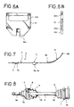
- Fig. 7 is a side view of the clamping band, which has been extended.
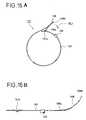
- the metallic clamping band 1 has a metallic band section 2. There is formed an engaging boss 3, whose one end is opened as an opening section 3a, in one end section of the band section 2. On the other hand, the other end of the band section 2 is fixed on a mid section of a lever 4 by spot welding. One end 4a of the lever 4 is capable of engaging with the opening section 3a of the engaging boss 3. A U-shaped clasp 5 is fixed on the band section 2 by spot welding. The clasp 5 is capable of fixing the other end 4b of the lever 4 when the one end 4a of the lever 4 is engaged with the opening section 3a of the engaging boss 3 and the lever 4 is turned.
- the clamping band 1 is the disengagable type clamping band which has been explained above, referring to Figs 16A and B.
- the end 4a of the lever 4 is located at a position between fixing pieces 5a when the lever 4 is completely turned down.
- Fig. 8 is a partial sectional view of joint boots whose ends are clamped by the clamping bands 1. External members 7a and 7b are connected with a shaft 6 by joints 8. The joints 8 are respectively covered with the joint boots 9. Lubricant of the joints 8, e.g., grease, is filled in the joint boots 9. Both ends of each boot 9 are clamped by the clamping bands 1 and 10, which have different inner diameter.
- a band clamping machine of the present embodiment which is capable of clamping the clamping bands 1 on the joint boots 9 will be explained.
- the clamping bands 1 are clamped by reducing inner diameter of their band sections 2.
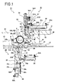
- central holding members 13A and 13B are provided in a center part of a base section 12 of the clamping machine 11.
- the central holding members 13A and 13B are vertically projected upwardly, and they have V-notches in upper end sections so that a main part of the shaft 6 and an end part 6a thereof, which is extended outwardly from the external member 7a, can be supported in the state that the shaft 6 is vertically arranged with respect to the drawing face of Fig. 1.
- the central supporting members 13A and 13B are capable of moving in the axial direction of the shaft 6.
- the positions of the central supporting members 13A and 13B can be changed according to size of the joint boot 9, and they are fixed at proper positions by bolts.
- end supporting members 14A and 14B are provided in the vicinity of the ends of the shaft 6.
- the end supporting members 14A and 14B respectively have V-notches, which are capable of supporting the end part 6a and the external member 7a.
- the end supporting members 14A and 14B are arranged parallel to the central supporting members 13A and 13B.
- the central supporting members 13A and 13B and the end supporting members 14A and 14B are capable of supporting the external member 7a, the main part and the end part 6a of the shaft 6.
- the clamping mechanism for clamping one of the clamping bands 1 and 10 is shown. Namely, the clamping mechanism for clamping the clamping band 1 having greater inner diameter is shown. Next, the clamping mechanism will be explained.
- the hole 12A is formed in the direction perpendicular to the axial direction of the shaft 6.
- the air hands 17 are driven by an air cylinder 19, so that they softly pinch both sides of the clamping band 1 to hold the clamping band 1 above the hole 12A.
- the clamping bands 1 can be axially and circumferentially positioned.
- the air hands 17 are formed into arc shapes, and they are capable of pinching the lower sides of the clamping member 1.
- the shaft 6, whose joint 8 is covered with the joint boot 9, etc. are supported by the notches of the central supporting members 13A and 13B and the end supporting members 14A and 14B.
- the clamping bands 1 and 10 which have mutually different diameter, are respectively fitted on the both ends of the joint boot 9.
- the clamping band 1 is located between the air hands 17, and the clasp 5 is located at uppermost position.
- a diameter reduction mechanism 20 which turns a lever 4 of the clamping band 1 to reduce the inner diameter of the looped clamping band 1, under the hole 12A of the base section 12.
- a fixing mechanism 22 which bends fixing pieces of the clasp 5 to fix the lever 4 onto an outer circumferential face of the looped clamping band 1, above the air hands 17 (the right part in Fig. 1).
- the air hands can be exchanged according to the size of the looped clamping band.
- a holding member 23 is provided in the hole 12A of the base section 12 and under the clamping band 1 which is being held by the air hands 17.
- the holding mechanism 23 is formed into an arc shape corresponding to the outer circumferential face of the looped clamping band 1.
- the holding member 23 contacts the lower end part of the clamping band 1 so as to support and position the clamping band 1 when the diameter reduction mechanism 20 is moved upward.
- the holding member 23 is fixed on an attaching plate 24 by a bolt; the attaching plate 24 is fixed to a mechanism proper 21, which is an example of a moving body, by a bolt.
- An clamping arm 25 is pivotably connected with the mechanism proper 21 at a position 25a.
- the clamping arm 25 is turned about the axis 25a, which is parallel to the axial line of the joint boot 9 on which the clamping band 1 is attached and which is located out side of the clamping band 1.
- the clamping arm 25 pushes an outer face of the lever 4 of the clamping band 1, which has been held by the air hands 17, and turns down the lever onto the outer circumferential face of the clamping band 1.
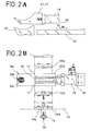
- a press roller 25b which contacts the lever 4 to support and bend the lever 4, at a front end of a front part 25A of the clamping arm 25.
- Press guides 25c which position the end of the lever 4 in the transverse direction, are respectively provided on both sides of the press roller 25b.
- a front end of a base part 25B of the clamping arm 25 is pivotably connected to a front end of a cylinder rod 26a of an arm driving cylinder (air cylinder) 26, which is an example of a second mechanism.
- the arm driving cylinder 26 is fixed to the mechanism proper 21 together with an attaching plate 27.
- the mechanism proper 21 is attached to an attaching plate 28, which is provided under the base section 12, and the mechanism proper 21 is accommodated in a frame 29 and capable of vertically moving therein.
- a vertical cylinder 30, which is an example of a first mechanism, is attached to a bottom plate 29a of the frame 29.
- a cylinder rod 30a of the vertical cylinder 30 is connected to a bottom of the mechanism proper 21. If the vertical cylinder 30 is driven, the mechanism proper 21 in the frame 29 is moved upward until the holding member 23 passes through the hole 12A of the base section 12 and contacts the lower circumferential face of the clamping band 1.
- the lever 4 is primarily bent from a holding position (an initial position) to a mid position with the press roller 25b.
- an adjusting screw 29b whose upper end is connected to the mechanism proper 21, to the bottom plate 29a, so nuts 29c contact the bottom face 20a when the vertical cylinder 30 is driven.
- the arm driving cylinder 26 and the vertical cylinder 30 constitute an arm driving mechanism.
- a supporting plate 31 which is provided on the right side of the L-shaped member 18 for supporting the air hands 17, is fixed on the base section 12 by bolts.
- a vertical block 32 is provided on the supporting plate 31.
- the vertical block 32 has a guide groove 32a, in which a slide block 33 is slidably fitted.
- the slide block 33 is capable of moving horizontally (in the right-left direction in Fig. 1) in the groove 32a.
- a base plate 34 is fixed to a front end (a left end in Fig. 1) of the slide block 33.
- a horizontal plate 36 is fixed to an upper end of the base plate 34.
- a press rod driving cylinder 36 and a punch driving cylinder 37 are provided on the horizontal plate 35.
- a positioning member 38 which is formed into an arc shape corresponding to an upper part of the clamping band 1, is attached to the lower front end (the lower left end in Fig. 1) of the slice block 33. The positioning member 38 contacts the upper-right circumferential face of the clamping band 1, which is being held by the air hands 17, to position the band 1.
- a movable cylinder 39 which moves the fixing mechanism 22, is provided above the guide block 32.
- a cylinder rod 39a of the movable cylinder 39 is connected to the base plate 34, so that the base plate 34 can be moved in the right-left direction in Fig. 1.
- the cylinder rod 39a is extended, so that the slide block 33 is moved along the guide groove 32a of the vertical block 32 together with the base plate 34 until the positioning member 38 contacts the upper-right circumferential face of the clamping band 1, which is being held by the air hands 17.
- a connecting member 40 is fixed at a rear end of the slide block 33 by volts.
- An upper end of the connecting member 40 is projected upward from the slide block 33, and an adjusting screw 41 is screwed with the projected end.
- a front end of the adjusting screw 41 is capable of contacting a right side face 32a of the vertical block 32. With this structure, forward movement of the slide block 33 can be limited.
- a controller 42 is fixed on the base section 12.
- the controller 42 controls the arm driving cylinder 26, the vertical cylinder 30, the press rod driving cylinder 36, the punch driving cylinder 37 and the movable cylinder 39.
- the air cylinders respectively have an air-port 26A, 30A, 36A, 37A or 39A and an air-port 26B, 30B, 36B, 37B or 39B.
- Compressed air is introduced to the air-ports 26A, 30A, 36A, 37A and 39A as input air-ports and the air in the cylinders are exhausted from the air-ports 26B, 30B, 36B, 37B and 39B as output air-ports so as to extend the cylinder rods; input air-ports and output air-ports are changed so as to retract the cylinder rods.
- An operating section (not shown) having control switches for the clamping operation is provided on the base section 12. Operating commands inputted through the operating section are transmitted to the controller 42 for the clamping operation.
- a compressor 43 compresses air and supplies the compressed air to the air cylinders.
- the compressor 43 is controlled by the controller 42 to extend and retract the cylinder rods.
- a shallow slide groove (not shown) in a front face (an upper side of the drawing face) of the base plate 34.
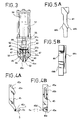
- a guide section 44a (see Fig. 5B) of the punch 44 is slidably fitted in the slide groove, so that the punch 44 is capable of vertically moving along the slide groove.
- the punch 44 is connected to the cylinder rod 37a of the punch driving cylinder 37.
- a pair of claw members 45 are provided on both sides of the guide groove 34a, under front lower part of the base plate 34.
- the claw members 45 are capable of respectively turning about axes 46.
- Upper inner faces of the claw members 45 which are mutually faced, are formed into slope faces 45a whose separation is gradually made narrower downward.
- Lower inner faces of the claw members 45a which are under the slope faces 45a, respectively have slits 45b (see Fig. 4B).
- Guide rollers 48 are respectively and rotatably attached in the slits 45b by axes 47, which are parallel to the axes 46.
- Pins 49 are projected from upper front faces of the claw members 45.
- Each end of a spring 50 which is an example of biasing means, is fixed to each pin 49, so that the upper parts of the claw members 45 are biased to mutually move close.
- the guide rollers 48 contact side faces of the punch 44.
- the front faces of the claw members 45 are covered with cover 51 (shown by dotted lines in Fig. 3).
- cover 51 shown by dotted lines in Fig. 3.
- the spacer 51 has a through-hole 51b corresponding to the spring 50.
- the spacer 51 has a slit 51c (see Fig. 6A) in a lower center part. An upper edge of the slit 51c is formed into a slope face 51d (see Fig. 6B).
- the punch 44 is located at an initial position or the uppermost position.
- the guide rollers 48 of the claw members 48 contact positions on the side faces of the punch 44, which are lower than the expanded sections 44b. If the punch driving cylinder 37 moves the punch downward, lower ends of the claw members 45 are moved close each other when the guide rollers 48 of the claw members 45 roll over the expanded sections 44b, so that the fixing pieces 5a of the clasp 5 are slightly bent inward.
- concave sections 45c there are respectively formed concave sections 45c in the lower ends of the claw members 45.
- the claw members 45 When the claw members 45 is moved in the tangent direction of the looped band section 2 and close to the clasp 5 of the clamping band 1, which has been pinched by the air hands 17, the clasp 5 can be fitted in the concave sections 45c.
- Sides of the concave sections 45c, which are on the clasp 5 sides, are opened, and their edges 45d are planed off so as to smoothly introduce the fixing pieces 5a into the concave sections 45c.
- Rear faces of the concave sections 45c act as stopper walls 45e.
- a pressing rod 52 on the front side of the punch, which is accommodated in the cover 51.
- the pressing rod 52 is arranged parallel to the punch 44.
- the pressing rod 52 is connected to a rod driving cylinder 36.
- a lower end of the pressing rod 52 is located under the lower end of the punch 44 and in the slit 51c of the cover 51.
- the pressing rod 52 and the rod driving cylinder 36 constitute a lever presser.
- the positioning member 38 moves the fixing mechanism 22 until reaching the outer circumferential face of the looped clamping band 1, which has been pinched by the air hands 17. Then the clamping arm 26 of the diameter reduction mechanism 20 completely turns the lever 4 down onto the outer circumferential face of the looped clamping band 1.
- the rod driving cylinder 36 moves the pressing rod 52 downward to press the front end section of the lever 4. By pressing with the pressing rod 52, spring back of the lever 4 can be prevented.
- the looped clamping bands 1 and 11 are attached on the both end sections of the joint boot 9, which covers the joint 8 of the shaft 6.
- the shaft 6 and the part 6a of the external member 7a are mounted in the notches of the central supporting members 13A and 13B and the end supporting members 14A and 14B, so that the clamping band 1 is located between the air hands 17.
- the clasp 5 of the clamping band 1 is located at the uppermost position.
- the air cylinder 19 is driven by the command inputted by the operating section so as to pinch the lower part of the clamping band 1 by the air hands 17 (see Fig. 1).
- the movable cylinder 39 is moved, and its cylinder rod 39a is extended.
- the slide block 33 which is supported by the vertical block 32, is moved forward.
- the clasp 5 enters the concave sections 45c of the claw members 45 via the opening edges 45d, and the clasp 5 contacts the stopper walls 45e of the concave sections 45c, so that the clasp 5 can be positioned therein.
- the stopper walls 45e of the concave sections 45 rotate the clasp 5 in the counterclockwise direction by the forward movement of the slide block 33, so that the clasp 5 can be located at the uppermost position.
- the slide block 33 is stopped when the positioning member 38 tightly contacts the outer circumferential face of the clamping band 1.
- the air hands 17 are capable of axially positioning the clamping band 1 whose clasp 5 is being located at the uppermost position; the positioning member 38 is capable of circumferentially positioning the same.
- the stop position of the slide block 33 can be adjusted by the adjusting screw 41, which is screwed with the connecting member 40 (see Fig. 11A).
- the clasp 5 of the clamping band 1 is positioned in the concave sections 45c. Then the vertical cylinder 30 is driven. The cylinder rod 30a of the vertical cylinder 30 is extended, so the diameter reduction mechanism 21 is moved upward in the frame 29 until the supporting member 23 passes through the hole 12A of the base section 12 and contacts the lower circumferential face of the clamping band 1. By this action, the clamping band 1 can be positioned.
- the lever 4 is primarily bent by the upward movement of the clamping arm 25. Namely, the lever 4, which is supported by the press roller 25b, is guided by the press guides 25c, and slightly turned in the clockwise direction.
- the stop position of the diameter reduction mechanism 21 can be adjusted by the adjusting screw 29b, which is screwed with the bottom plate 29a (see Fig. 9).
- the arm driving cylinder 26 is driven to extend the cylinder rod 26a, so that the clamping arm 25 is turned about the point 25a in the clockwise direction.
- the press roller 25b pushes the lever 4 to turn down onto the outer circumferential face of the clamping band 1.
- the diameter reduction mechanism 21 is moved upward, the lever 4 has already been primarily bent in the clockwise direction, so the lever 4 can be smoothly and completely turned by the clamping arm 25.
- the lever 4 is turned, the end of the lever 4 is passed through the slit 51c of the cover 51 and a space between the claw members 45 and reached a position between the fixing pieces 5a.
- the press roller 25b is not located between the fixing pieces 5a, which have been located at the uppermost position, and the press roller 25b presses the lever 4 at a position under the uppermost position (see Fig. 10A). Note that, since the lever 4 has been positioned and supported by the press roller 25b and the press guides 25c when the shaft 6 is set, the clasp 5 of the clamping band 1 is not shifted leftward with respect to the uppermost position (see Fig. 1).
- the rod driving cylinder 36 is driven to move the press rod 52 downward.
- the lever 4 is pressed onto the outer circumferential face of the clamping band 1.
- the press rod 52 presses a position on the lever 4 which is in the vicinity of the fixing pieces 5a (see Fig. 10B), so that the end of the lever 4 can be prevented from rising. Namely, the spring back of the lever 4 can be prevented, and the lever 4 can be securely fixed by bending the fixing pieces 5a.
- the punch cylinder 37 is driven to move the punch 44 downward.
- the lower ends of the claw members 45 are once moved close each other when the guide rollers 48 roll over the expanded sections 44b of the punch 44.
- the fixing pieces 5a of the clasp 5 are slightly bent inward.
- a bottom face of the punch 44 contacts upper edges of the fixing pieces 5a, so the fixing pieces 5a are further bent inward to fix the lever 4.
- the joint boot 9 is completely clamped by the clamping band 1.
- the punch driving cylinder 37 and the rod driving cylinder 36 are reversely driven to move the punch 44 and the press rod 52 away from the clamping band 1.
- the arm cylinder 26 is also reversely driven to turn the clamping arm 25 about the point 25a in the counterclockwise direction to move away from the clamping band 1.
- the movable cylinder 39 is reversely driven to move the slide block 33 backward (the rightward in Fig. 1) and to move the positioning member 38 away from the clamping band 1.
- the vertical cylinder 30 is reversely driven to move the diameter reduction mechanism 21 downward along the frame 29, so that the holding member 23 is moved away from the clamping band 1.
- the air cylinder 19 is reversely driven to release the clamping band 1 from the air hands 17, so that the shaft 6 and the joint boot 9, whose end is clamped by the clamping band 1, can be taken out from the supporting members.
- the overlapped type clamping bands which are previously formed into loop shapes, and the disengagable type clamping bands can be employed to clamp the joint boots, etc..
- the members to be clamped e.g., the joint boots, are once set on the supporting members, they can be automatically clamped by the clamping bands. Without manual operations, the clamping work can be automatically and efficiently.
- the clamping band can clamp the member to be stably clamped with fixed clamping force.
- the lever is pressed by the press rod while the fixing pieces are bent, and the fixing pieces are bent without using a hammer, so the clamping work can be securely and safely executed.
- the members to be clamped can be reliably clamped.
- the band clamping machine 11 clamps the clamping band 1, which clamps the one end of the joint boot 9 of the external member 7a.
- the other end of the joint boot 9 can be clamped by the clamping band 10 by the same manner.
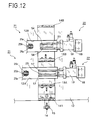
- Fig. 12 shows the band clamping machine, which is capable of simultaneously clamping the both ends of the joint boot 9 of the external member 7a by the clamping bands 1 and 10 (see Fig. 8), whose inner diameter is different each other. Note that, the constituting members shown in Figs. 1-11B are assigned the same symbols, and explanation will be omitted.
- the central holding members 13A and 13B are provided in the center part of the base section 12 of the band clamping machine 11.
- Two pair of air hands 17 and 54, which can respectively pinch the clamping bands 1 and 10, are respectively provided above the holes 12A and 12B of the base section 12.
- the air hands 17 and 54 are formed into the arc shapes corresponding to the lower sides of the joint boot 9.
- the separation between the air hands 17 and the air hands 54 is designed that the clamping band 1 is located between the air hands 17 and the clamping band 10 is located between the air hands 54 when the shaft 6 and the end part 6a of the external member 7a are set in the notches of the central supporting members 13A and 13B and the end supporting members 14A and 14B.
- the diameter reduction mechanisms 20 are respectively provided under the air hands 17 and 54; the fixing mechanisms 22 are respectively provided right side thereof.
- the automatic clamping work can be executed. Namely, the both ends of the joint boot 9 can be automatically and simultaneously clamped by the clamping bands 1 and 10.
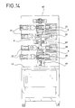
- each joint boot 9 which cover the joints 8 of the shaft 6, are provided to both ends of the shaft 6 (see Fig. 8), the both ends of each joint boot 9 are simultaneously clamped by the clamping bands 1, which have greater inner diameter, and the clamping bands 10, which have smaller inner diameter as shown in Fig. 13.
- the air hands 17 and hands 54 (see Fig. 12), the diameter reduction mechanisms 20 and the fixing mechanisms 22 are provided both sides of the shaft 6.
- the both ends of each joint boot 9 (see Fig. 8) can be simultaneously clamped by four clamping bands 1 and 10.
- the shaft 6, which has the joints 8 and the joint boots, may be horizontally mounted on the supporting members 55, 56 and 57, and the both ends of the shaft 6 may be positioned by jigs 58 and 59 to clamp by the clamping bands 1 and 10.
- the both ends of the shaft 6, which is vertically arranged are fixed to and positioned by jigs 60 and 61.
- the mid section of the shaft 6 is fixed by a jig 62.
- the shaft 6 can be vertically arranged and the both joint boots 9 can be simultaneously clamped by four clamping bands 1 and 10.
- the vertical type band clamping machine can be installed in smaller area.
- the arrangement of the supporting members and the number of the air hands, the diameter reduction mechanisms and the fixing mechanisms may be changed according to the size of the members to be clamped, the number of the clamping bands, etc..
Landscapes
- Engineering & Computer Science (AREA)
- Mechanical Engineering (AREA)
- General Engineering & Computer Science (AREA)
- Clamps And Clips (AREA)
- Basic Packing Technique (AREA)
Applications Claiming Priority (3)
| Application Number | Priority Date | Filing Date | Title |
|---|---|---|---|
| JP66386/96 | 1996-03-22 | ||
| JP06638696A JP3845141B2 (ja) | 1996-03-22 | 1996-03-22 | 締付けバンドの締付け機 |
| JP6638696 | 1996-03-22 |
Publications (3)
| Publication Number | Publication Date |
|---|---|
| EP0796697A2 true EP0796697A2 (fr) | 1997-09-24 |
| EP0796697A3 EP0796697A3 (fr) | 1998-03-25 |
| EP0796697B1 EP0796697B1 (fr) | 2003-05-21 |
Family
ID=13314345
Family Applications (1)
| Application Number | Title | Priority Date | Filing Date |
|---|---|---|---|
| EP97301562A Expired - Lifetime EP0796697B1 (fr) | 1996-03-22 | 1997-03-10 | Machine pour serrer un collier de serrage |
Country Status (8)
| Country | Link |
|---|---|
| US (1) | US5933938A (fr) |
| EP (1) | EP0796697B1 (fr) |
| JP (1) | JP3845141B2 (fr) |
| KR (1) | KR100226094B1 (fr) |
| AU (1) | AU682293B1 (fr) |
| CA (1) | CA2200256C (fr) |
| DE (1) | DE69722062T2 (fr) |
| TW (1) | TW330904B (fr) |
Cited By (3)
| Publication number | Priority date | Publication date | Assignee | Title |
|---|---|---|---|---|
| CN102874425A (zh) * | 2011-07-13 | 2013-01-16 | 赖建发 | 捆包机的退带束紧机构 |
| CN103158003A (zh) * | 2011-12-08 | 2013-06-19 | 苏州工业园区高登威科技有限公司 | 一种用于制造卡箍的系统 |
| CN110125862A (zh) * | 2019-05-11 | 2019-08-16 | 佛山市南海耀龙管业科技有限公司 | 一种道旗灯杆安装用辅助装置 |
Families Citing this family (5)
| Publication number | Priority date | Publication date | Assignee | Title |
|---|---|---|---|---|
| US6244967B1 (en) * | 1997-09-30 | 2001-06-12 | Ntn Corporation | Constant velocity joint with resin boot |
| WO2012106617A1 (fr) * | 2011-02-03 | 2012-08-09 | A. Raymond Et Cie | Appareil et méthode de formation de bride |
| KR101684783B1 (ko) * | 2015-05-13 | 2016-12-20 | 신우신 주식회사 | 밴드 클램프 체결장치 |
| CN107464688B (zh) * | 2017-09-15 | 2019-12-17 | 广东电网有限责任公司电力科学研究院 | 一种电线线圈加工设备 |
| KR102314161B1 (ko) | 2021-03-30 | 2021-10-18 | 윤미정 | 밴드 체결기 |
Family Cites Families (35)
| Publication number | Priority date | Publication date | Assignee | Title |
|---|---|---|---|---|
| US1848867A (en) * | 1932-03-08 | For- inserting couplings in flexible hose | ||
| US224586A (en) * | 1880-02-17 | Hose-band | ||
| US1927688A (en) * | 1930-12-08 | 1933-09-19 | Hose Stayput Tool Company | Method and means for making hose connections |
| US2348957A (en) * | 1941-09-12 | 1944-05-16 | Crown Cork & Seal Co | Apparatus for and method of making circular locking bands for caps or closures |
| US2382359A (en) * | 1942-05-02 | 1945-08-14 | Budd Edward G Mfg Co | Apparatus for applying bands to tubular articles |
| US2696745A (en) * | 1952-09-12 | 1954-12-14 | Charles G Cooper | Tool for applying bands to conduits |
| US2954813A (en) * | 1958-02-14 | 1960-10-04 | Brumley Donaldson Company | Buckle and strap tying machine |
| US3172384A (en) * | 1963-01-14 | 1965-03-09 | John J Tipton | Pipe line clamp |
| US3213529A (en) * | 1963-05-10 | 1965-10-26 | John B Gill | Device for displacing couplings having a plurality of chain sections and anchor members with a thrust member to move a pipe |
| US3364555A (en) * | 1965-10-20 | 1968-01-23 | Edward K. Swink | Soil pipe assembly device |
| US3368270A (en) * | 1966-04-26 | 1968-02-13 | Theodore H. Babian | Shank type coupler and adapter inserter |
| US3583056A (en) * | 1968-09-16 | 1971-06-08 | Rheem Mfg Co | Clipping device |
| JPS5014702A (fr) * | 1973-06-09 | 1975-02-17 | ||
| CH580473A5 (fr) * | 1974-07-08 | 1976-10-15 | Oetiker Hans | |
| ES209592Y (es) * | 1975-01-24 | 1976-09-01 | Lorenzo Barroso | Una grapadora. |
| US4173815A (en) * | 1976-07-22 | 1979-11-13 | Robertshaw Controls Company | Method of joining two abutting metal members together |
| DE2812086C3 (de) * | 1977-03-30 | 1981-02-26 | Ntn Toyo Bearing Co. Ltd., Osaka (Japan) | Vorrichtung zum Befestigen eines Metallklemmbandes um einen mit einer Hülse versehenen zylindrischen Körper |
| FR2450671A1 (fr) * | 1979-03-09 | 1980-10-03 | Seperef | Appareil d'emboitement ou de deboitement des embouts de tubes ou tuyaux a raccordement par garniture d'etancheite |
| US4339940A (en) * | 1980-06-05 | 1982-07-20 | Tipper Tie, Inc. | Multipart die for attachment of a metal clip |
| SU1054007A1 (ru) * | 1981-09-03 | 1983-11-15 | Всесоюзный Проектно-Технологический Институт Тяжелого Машиностроения | Устройство дл сборки роликов |
| US4982484A (en) * | 1982-03-26 | 1991-01-08 | Micro-Precision Operations Inc. | Apparatus for assembling internal retainer ring having lugs into a bore |
| SU1127737A1 (ru) * | 1983-04-12 | 1984-12-07 | Волжское объединение по производству легковых автомобилей | Устройство дл сборки деталей с нат гом |
| JPH01205941A (ja) * | 1988-02-10 | 1989-08-18 | Daido Metal Co Ltd | 止め輪装着装置 |
| US5044814A (en) * | 1989-01-18 | 1991-09-03 | Kabushiki Kaisha Mihama Seisakusho | Clamping band |
| JPH0723723B2 (ja) * | 1989-01-18 | 1995-03-15 | 株式会社ミハマ製作所 | 締付けバンド |
| US4884432A (en) * | 1989-02-21 | 1989-12-05 | Camco, Incorporated | Backup for a clamp crimper |
| JP2875298B2 (ja) * | 1989-09-08 | 1999-03-31 | 株式会社ミハマ製作所 | 締付けバンドおよび締付けバンドの取付装置 |
| JP2828313B2 (ja) * | 1990-04-24 | 1998-11-25 | 株式会社ミハマ製作所 | 金属製締付けバンドの成形機 |
| GB2247295B (en) * | 1990-08-20 | 1994-03-09 | British Gas Plc | Method and apparatus for positioning components |
| DE4036015A1 (de) * | 1990-11-13 | 1992-05-14 | Wolfgang Koehler | Verfahren und vorrichtung zum befestigen von halteklammern an einem band |
| US5269054A (en) * | 1992-05-15 | 1993-12-14 | Delaware Capital Formation, Inc. | Clip attachment apparatus |
| JPH061307A (ja) * | 1992-06-17 | 1994-01-11 | Mihama Seisakusho:Kk | 締付けバンドの締付け機 |
| US5390395A (en) * | 1993-12-09 | 1995-02-21 | Hans Oetiker Ag Maschioen- Und Apparatefabrik | Earless, stepless clamp structure |
| US5548876A (en) * | 1995-03-01 | 1996-08-27 | Hans Oetiker Ag Maschinen- Und Apparatefabrik | Lever-type clamp |
| CA2169698C (fr) * | 1995-11-01 | 2001-03-13 | Taira Hama | Bande de serrage |
-
1996
- 1996-03-22 JP JP06638696A patent/JP3845141B2/ja not_active Expired - Lifetime
-
1997
- 1997-03-04 US US08/808,780 patent/US5933938A/en not_active Expired - Lifetime
- 1997-03-10 EP EP97301562A patent/EP0796697B1/fr not_active Expired - Lifetime
- 1997-03-10 DE DE69722062T patent/DE69722062T2/de not_active Expired - Lifetime
- 1997-03-14 TW TW086103220A patent/TW330904B/zh active
- 1997-03-18 CA CA002200256A patent/CA2200256C/fr not_active Expired - Lifetime
- 1997-03-21 AU AU16428/97A patent/AU682293B1/en not_active Ceased
- 1997-03-22 KR KR1019970009912A patent/KR100226094B1/ko not_active Expired - Lifetime
Cited By (5)
| Publication number | Priority date | Publication date | Assignee | Title |
|---|---|---|---|---|
| CN102874425A (zh) * | 2011-07-13 | 2013-01-16 | 赖建发 | 捆包机的退带束紧机构 |
| CN102874425B (zh) * | 2011-07-13 | 2014-11-05 | 赖建发 | 捆包机的退带束紧机构 |
| CN103158003A (zh) * | 2011-12-08 | 2013-06-19 | 苏州工业园区高登威科技有限公司 | 一种用于制造卡箍的系统 |
| CN110125862A (zh) * | 2019-05-11 | 2019-08-16 | 佛山市南海耀龙管业科技有限公司 | 一种道旗灯杆安装用辅助装置 |
| CN110125862B (zh) * | 2019-05-11 | 2020-11-20 | 广东耀龙金属科技有限公司 | 一种道旗灯杆安装用辅助装置 |
Also Published As
| Publication number | Publication date |
|---|---|
| JP3845141B2 (ja) | 2006-11-15 |
| EP0796697B1 (fr) | 2003-05-21 |
| DE69722062D1 (de) | 2003-06-26 |
| TW330904B (en) | 1998-05-01 |
| DE69722062T2 (de) | 2004-03-11 |
| KR970064833A (ko) | 1997-10-13 |
| CA2200256A1 (fr) | 1997-09-22 |
| US5933938A (en) | 1999-08-10 |
| CA2200256C (fr) | 2001-06-05 |
| JPH09254917A (ja) | 1997-09-30 |
| KR100226094B1 (ko) | 1999-10-15 |
| AU682293B1 (en) | 1997-09-25 |
| EP0796697A3 (fr) | 1998-03-25 |
Similar Documents
| Publication | Publication Date | Title |
|---|---|---|
| EP0796697B1 (fr) | Machine pour serrer un collier de serrage | |
| EP1219363B1 (fr) | Dispositif de cintrage pour matériau allongé | |
| US20090139293A1 (en) | Hemming method and hemming apparatus | |
| US6116588A (en) | Clamping device | |
| US4144628A (en) | Method and device for fixing joining clamps on a conveyor band, belt or the like | |
| CA2874066A1 (fr) | Appareillage et methode d'insertion de plaques angulaires et de fermeture de joints de conduite | |
| EP1611972B1 (fr) | Procédé et dispositif pour fabriquer un bord rabattu à 180° | |
| JPH04211705A (ja) | クランプの自動組付締付方法およびその装置 | |
| CN212793836U (zh) | 插接辅助装置 | |
| EP0406301B1 (fr) | Machine a plier | |
| KR101716095B1 (ko) | 핀 터미널 압착기 | |
| KR100412473B1 (ko) | 자동차용 클립호스 오픈 지그장치 | |
| JPH06297046A (ja) | ヘミング加工方法およびヘミング加工装置 | |
| EP0575138B1 (fr) | Dispositif de serrage pour un collier | |
| US20240261844A1 (en) | Compact device for crimping edges of metal sheets, associated crimping unit and method | |
| US6467144B1 (en) | Multifunction insert press | |
| KR101906861B1 (ko) | 가공지선지지대 제조장치 | |
| JP4005686B2 (ja) | ワークのクランプ機構 | |
| US5930880A (en) | Intensification method and apparatus for hemming machine | |
| JPH0747135Y2 (ja) | 長尺なワークの軸線曲げ装置 | |
| KR100258399B1 (ko) | 시일레스 스트랩 유지장치 및 방법 | |
| JPH0618653Y2 (ja) | プレス型構造 | |
| KR102763112B1 (ko) | 소량 다품종 차체패널용 헤밍장치 | |
| GB1578055A (en) | Crimping tool | |
| JP3679032B2 (ja) | 止め輪取り付け用工具 |
Legal Events
| Date | Code | Title | Description |
|---|---|---|---|
| PUAI | Public reference made under article 153(3) epc to a published international application that has entered the european phase |
Free format text: ORIGINAL CODE: 0009012 |
|
| AK | Designated contracting states |
Kind code of ref document: A2 Designated state(s): CH DE FR GB IT LI SE |
|
| PUAL | Search report despatched |
Free format text: ORIGINAL CODE: 0009013 |
|
| AK | Designated contracting states |
Kind code of ref document: A3 Designated state(s): CH DE FR GB IT LI SE |
|
| 17P | Request for examination filed |
Effective date: 19980306 |
|
| 17Q | First examination report despatched |
Effective date: 20010914 |
|
| GRAG | Despatch of communication of intention to grant |
Free format text: ORIGINAL CODE: EPIDOS AGRA |
|
| GRAG | Despatch of communication of intention to grant |
Free format text: ORIGINAL CODE: EPIDOS AGRA |
|
| GRAG | Despatch of communication of intention to grant |
Free format text: ORIGINAL CODE: EPIDOS AGRA |
|
| GRAH | Despatch of communication of intention to grant a patent |
Free format text: ORIGINAL CODE: EPIDOS IGRA |
|
| GRAH | Despatch of communication of intention to grant a patent |
Free format text: ORIGINAL CODE: EPIDOS IGRA |
|
| RBV | Designated contracting states (corrected) |
Designated state(s): DE FR GB IT SE |
|
| GRAA | (expected) grant |
Free format text: ORIGINAL CODE: 0009210 |
|
| AK | Designated contracting states |
Designated state(s): DE FR GB IT SE |
|
| REG | Reference to a national code |
Ref country code: GB Ref legal event code: FG4D |
|
| REF | Corresponds to: |
Ref document number: 69722062 Country of ref document: DE Date of ref document: 20030626 Kind code of ref document: P |
|
| REG | Reference to a national code |
Ref country code: SE Ref legal event code: TRGR |
|
| ET | Fr: translation filed | ||
| PLBE | No opposition filed within time limit |
Free format text: ORIGINAL CODE: 0009261 |
|
| STAA | Information on the status of an ep patent application or granted ep patent |
Free format text: STATUS: NO OPPOSITION FILED WITHIN TIME LIMIT |
|
| 26N | No opposition filed |
Effective date: 20040224 |
|
| PGFP | Annual fee paid to national office [announced via postgrant information from national office to epo] |
Ref country code: GB Payment date: 20050228 Year of fee payment: 9 |
|
| PGFP | Annual fee paid to national office [announced via postgrant information from national office to epo] |
Ref country code: SE Payment date: 20050323 Year of fee payment: 9 |
|
| PG25 | Lapsed in a contracting state [announced via postgrant information from national office to epo] |
Ref country code: GB Free format text: LAPSE BECAUSE OF NON-PAYMENT OF DUE FEES Effective date: 20060310 |
|
| PG25 | Lapsed in a contracting state [announced via postgrant information from national office to epo] |
Ref country code: SE Free format text: LAPSE BECAUSE OF NON-PAYMENT OF DUE FEES Effective date: 20060311 |
|
| PGFP | Annual fee paid to national office [announced via postgrant information from national office to epo] |
Ref country code: IT Payment date: 20060331 Year of fee payment: 10 |
|
| EUG | Se: european patent has lapsed | ||
| GBPC | Gb: european patent ceased through non-payment of renewal fee |
Effective date: 20060310 |
|
| PG25 | Lapsed in a contracting state [announced via postgrant information from national office to epo] |
Ref country code: IT Free format text: LAPSE BECAUSE OF NON-PAYMENT OF DUE FEES Effective date: 20070310 |
|
| REG | Reference to a national code |
Ref country code: FR Ref legal event code: PLFP Year of fee payment: 19 |
|
| REG | Reference to a national code |
Ref country code: FR Ref legal event code: PLFP Year of fee payment: 20 |
|
| PGFP | Annual fee paid to national office [announced via postgrant information from national office to epo] |
Ref country code: DE Payment date: 20160324 Year of fee payment: 20 |
|
| PGFP | Annual fee paid to national office [announced via postgrant information from national office to epo] |
Ref country code: FR Payment date: 20160324 Year of fee payment: 20 |
|
| REG | Reference to a national code |
Ref country code: DE Ref legal event code: R071 Ref document number: 69722062 Country of ref document: DE |